EP0814552B1 - Anschluss und Anschlusszusammenbau für ein geschirmtes Koaxialkabel - Google Patents
Anschluss und Anschlusszusammenbau für ein geschirmtes Koaxialkabel Download PDFInfo
- Publication number
- EP0814552B1 EP0814552B1 EP19960109865 EP96109865A EP0814552B1 EP 0814552 B1 EP0814552 B1 EP 0814552B1 EP 19960109865 EP19960109865 EP 19960109865 EP 96109865 A EP96109865 A EP 96109865A EP 0814552 B1 EP0814552 B1 EP 0814552B1
- Authority
- EP
- European Patent Office
- Prior art keywords
- terminal
- teeth
- pair
- base portion
- housing
- Prior art date
- Legal status (The legal status is an assumption and is not a legal conclusion. Google has not performed a legal analysis and makes no representation as to the accuracy of the status listed.)
- Expired - Lifetime
Links
Images

Classifications
-
- H—ELECTRICITY
- H01—ELECTRIC ELEMENTS
- H01R—ELECTRICALLY-CONDUCTIVE CONNECTIONS; STRUCTURAL ASSOCIATIONS OF A PLURALITY OF MUTUALLY-INSULATED ELECTRICAL CONNECTING ELEMENTS; COUPLING DEVICES; CURRENT COLLECTORS
- H01R4/00—Electrically-conductive connections between two or more conductive members in direct contact, i.e. touching one another; Means for effecting or maintaining such contact; Electrically-conductive connections having two or more spaced connecting locations for conductors and using contact members penetrating insulation
- H01R4/24—Connections using contact members penetrating or cutting insulation or cable strands
- H01R4/2495—Insulation penetration combined with permanent deformation of the contact member, e.g. crimping
-
- H—ELECTRICITY
- H01—ELECTRIC ELEMENTS
- H01R—ELECTRICALLY-CONDUCTIVE CONNECTIONS; STRUCTURAL ASSOCIATIONS OF A PLURALITY OF MUTUALLY-INSULATED ELECTRICAL CONNECTING ELEMENTS; COUPLING DEVICES; CURRENT COLLECTORS
- H01R9/00—Structural associations of a plurality of mutually-insulated electrical connecting elements, e.g. terminal strips or terminal blocks; Terminals or binding posts mounted upon a base or in a case; Bases therefor
- H01R9/03—Connectors arranged to contact a plurality of the conductors of a multiconductor cable, e.g. tapping connections
- H01R9/05—Connectors arranged to contact a plurality of the conductors of a multiconductor cable, e.g. tapping connections for coaxial cables
- H01R9/053—Connectors arranged to contact a plurality of the conductors of a multiconductor cable, e.g. tapping connections for coaxial cables using contact members penetrating insulation
Definitions
- Terminals or terminal assemblies often are used to terminate the conductive shield of the coaxial cable. Typically, this is accomplished by a terminal with some form of crimp barrel or other means having teeth which pierce the outer insulating jacket and contact the strands of the braided shield. Many such teeth are required to provide an adequate contacting interface. The pressure against the braid by such teeth is quite random, and the combination affects the dielectric properties of the cable. Specifically, the cable impedance can be affected by such terminals, because the terminals often result in considerable deformation of the dielectric sheath about the center conductor.
Landscapes
- Multi-Conductor Connections (AREA)
- Details Of Connecting Devices For Male And Female Coupling (AREA)
- Coupling Device And Connection With Printed Circuit (AREA)
Claims (15)
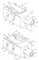
- Anschlußanordnung (10) mit folgenden Merkmalen:dadurch gekennzeichnet, dass die Zähne (68, 70) in Richtung (B) generell tangential zu der dielektrischen Hülle (22) ausgerichtet sind, um einen Teil (80) der Abschirmung (12) zwischen den Zähnen (68, 70) einzuklemmen, ohne im wesentlichen die dielektrische Hülle (22) zu beeinträchtigen.ein abgeschirmtes isoliertes Kabel (14) weist einen Leiterkern (20), eine dielektrische Hülle (22),eine Abschirmung (12) und einen äußeren Isoliermantel (24) auf, wobei die Abschirmung (12) zwischen der dielektrischen Hülle (22) und dem Isoliermantel (24) angeordnet ist;ein dielektrisches Gehäuse (16) weist eine Klemmenaufnahme (38) auf;eine Klemme (18) wird in der Aufnahme (38) des Gehäuses aufgenommen und umfasst Zahnpaare (68, 70), die aufeinander zu bewegbar sind, um den äußeren Isoliermantel (24) zu durchstoßen,
- Anschlußanordnung nach Anspruch 1,
worin die Klemme (18) zwei Paare der Zähne (68, 70) umfasst mit jeweils einem Paar an jeder entgegengesetzten Seite des Kabels (14). - Anschlußanordnung nach Anspruch 1 oder 2,
worin die Klemme (18) einen verformbaren Arm (72) umfasst, der die Zähne im jeweiligen Paar integral verbindet. - Anschlußanordnung nach Ansprüchen 1, 2 oder 3,
worin die Klemme (18) aus Blech gefertigt ist. - Anschlußanordnung nach einem der Ansprüche 1 bis 4,
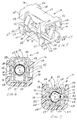
dadurch gekennzeichnet, dass die Klemme (18) einen Basisteil (50) und einen Druckteil (52) umfasst, wobei der Basisteil um einen vorbestimmten Abstand oberhalb einer feststehenden Wand (32) der Aufnahme des Gehäuses angeordnet ist und der Druckteil (52) zum Basisteil hin bewegbar ist, und dass einer der Zähne (68, 70) des Paares in dem Basisteil (50) bzw. dem Druckteil (52) der Klemme angeordnet ist. - Anschlußanordnung nach einem der Ansprüche 1 bis 5,
worin die Klemme (18) einen deformierbaren Arm (72) umfasst, der den Basisteil (50) mit dem Druckteil (52) der Klemme integral verbindet. - Anschlußanordnung nach einem der Ansprüche 5 oder 6,
worin der Anschluß (18) aus Blech gefertigt ist. - Anschlußanordnung nach einem der Ansprüche 1 bis 5,
dadurch gekennzeichnet, dass komplementäre ineinandergreifende Verriegelungsmittel (46, 60) zwischen dem Gehäuse (16) und dem bewegbaren Teil (52) der Klemme (18) vorgesehen sind, um den Druckteil in einer betätigten Stellung zu halten und dabei die Zähne (68, 70) in ihrer Klemmposition zu halten. - Anschlußanordnung (10) nach einem der Ansprüche 1 bis 8,
dadurch gekennzeichnet,dass das dielektrische Gehäuse (16) eine Zugangsöffnung (40) durch eine Wandung (34) des Gehäuses zu der Aufnahme (38) aufweist unddass je ein Paar von Zähnen (68, 70) an entgegensetzen Seiten der Aufnahme (38) angeordnet ist, wobei ein Zahn des Paares jeweils auf dem Basisteil (50) bzw. dem Druckteil (52) der Klemme (18) angeordnet ist. - Anschlußanordnung nach einem der Ansprüche 1 bis 9,
dadurch gekennzeichnet, dass das Gehäuse ein Loch (42) umfasst, in welches der deformierbare Arm (72) hineinragt, wenn der Druckteil (52) der Klemme (18) zum Basisteil (50) der Klemme bewegt wird. - Klemme (18) zum Anschließen einer Abschirmung (12) eines geschirmten isolierten Kabels (14) mit einem Leiterkern (20), einer dielektrischen Hülle (22) und einem äußeren Isoliermantel (24), wobei die Abschirmung zwischen der dielektrischen Hülle und dem Isoliermantel angeordnet ist,
umfassend einen kollabierbaren Körper mit sich gegenüberstehenden und aufeinander zu bewegbaren Zähnen (68, 70), um den äußeren Isoliermantel (24) zu durchstoßen,
dadurch gekennzeichnet,dass die Zähne (68, 70) zwei Paare sich gegenüberstehender Zähne bilden,dass die Zähne eines Paares in einem seitlichen Abstand entsprechend dem Durchmesser der Hülle (22) und gegenüber den Zähnen des anderen Paares angeordnet sind,so dass, wenn sich gegenüberstehende Zähne des einen Paares in Richtung (B) generell tangential zu der dielektrischen Hülle (22) verschoben werden, ein Teil (80) der Abschirmung (12) zwischen die Zähne (68, 70) geklemmt wird, ohne die dielektrische Hülle (22) zu beeinträchtigen. - Klemme nach Anspruch 11,
umfassend einen deformierbaren Arm (72), der die Zähne in seinem zugehörigen Paar miteinander integral verbindet. - Klemme nach Anspruch 11 oder 12,
umfassend einen Basisteil (50) und einen Druckteil (52), der zu dem Basisteil hin verschiebbar ist, wobei ein Zahn (68, 70) des Paares jeweils auf dem Basisteil (50) bzw. dem Druckteil (52) angeordnet ist. - Klemme nach einem der Ansprüche 11 bis 13,
umfassend einen deformierbaren Arm (52), der den Basisteil (50) und den Druckteil (52) integral miteinander verbindet. - Klemme nach einem der Ansprüche 11 bis 14,
worin die Klemme (18) aus Blech gefertigt ist.
Priority Applications (2)
| Application Number | Priority Date | Filing Date | Title |
|---|---|---|---|
| EP19960109865 EP0814552B1 (de) | 1996-06-19 | 1996-06-19 | Anschluss und Anschlusszusammenbau für ein geschirmtes Koaxialkabel |
| DE1996618449 DE69618449T2 (de) | 1996-06-19 | 1996-06-19 | Anschluss und Anschlusszusammenbau für ein geschirmtes Koaxialkabel |
Applications Claiming Priority (1)
| Application Number | Priority Date | Filing Date | Title |
|---|---|---|---|
| EP19960109865 EP0814552B1 (de) | 1996-06-19 | 1996-06-19 | Anschluss und Anschlusszusammenbau für ein geschirmtes Koaxialkabel |
Publications (2)
| Publication Number | Publication Date |
|---|---|
| EP0814552A1 EP0814552A1 (de) | 1997-12-29 |
| EP0814552B1 true EP0814552B1 (de) | 2002-01-09 |
Family
ID=8222908
Family Applications (1)
| Application Number | Title | Priority Date | Filing Date |
|---|---|---|---|
| EP19960109865 Expired - Lifetime EP0814552B1 (de) | 1996-06-19 | 1996-06-19 | Anschluss und Anschlusszusammenbau für ein geschirmtes Koaxialkabel |
Country Status (2)
| Country | Link |
|---|---|
| EP (1) | EP0814552B1 (de) |
| DE (1) | DE69618449T2 (de) |
Families Citing this family (5)
| Publication number | Priority date | Publication date | Assignee | Title |
|---|---|---|---|---|
| US6135805A (en) * | 1998-08-04 | 2000-10-24 | Mandex Manufacturing Corporation | Insulation displacement device for wire termination |
| FR2786929B1 (fr) * | 1998-12-07 | 2006-09-29 | Cahors App Elec | Dispositif pour raccorder un cable electrique isole par une gaine exterieure, a un ou plusieurs autres conducteurs |
| DE102004004309B4 (de) * | 2004-01-28 | 2005-11-03 | U.I. Lapp Gmbh | Vorrichtung zur Kontaktierung eines Schirmgeflechts eines geschirmten elektrischen Kabels |
| US6988911B2 (en) * | 2004-03-02 | 2006-01-24 | Tyco Electronics Corporation | Coaxial cable connector with improved shielding |
| CN118884021B (zh) * | 2024-07-08 | 2025-03-18 | 北京中科飞龙传感技术有限责任公司 | 具有屏蔽腔体的硬压板电压监测装置、组装方法及系统 |
Family Cites Families (3)
| Publication number | Priority date | Publication date | Assignee | Title |
|---|---|---|---|---|
| GB2124041B (en) * | 1982-07-23 | 1985-11-27 | Molex Inc | Insulation displacement terminal for an electrical connector and environmental sealing means therefor |
| US5066248A (en) * | 1991-02-19 | 1991-11-19 | Lrc Electronics, Inc. | Manually installable coaxial cable connector |
| US5362251A (en) * | 1993-02-09 | 1994-11-08 | Switchcraft Inc. | Solderless coaxial connector plug |
-
1996
- 1996-06-19 DE DE1996618449 patent/DE69618449T2/de not_active Expired - Fee Related
- 1996-06-19 EP EP19960109865 patent/EP0814552B1/de not_active Expired - Lifetime
Also Published As
| Publication number | Publication date |
|---|---|
| DE69618449D1 (de) | 2002-02-14 |
| EP0814552A1 (de) | 1997-12-29 |
| DE69618449T2 (de) | 2002-09-12 |
Similar Documents
| Publication | Publication Date | Title |
|---|---|---|
| EP0653803B1 (de) | Elektrischer Schneidklemmverbinder mit verbesserter Zugentlastung | |
| US5542861A (en) | Coaxial connector | |
| US5716236A (en) | System for terminating the shield of a high speed cable | |
| EP0793305B1 (de) | Kabel mit verdrillten Leitungspaaren und Verbinderanordnung | |
| US4737118A (en) | Hermaphroditic flat cable connector | |
| EP1003250B1 (de) | Ein abgeschirmter Verbinder, ein abgeschirmtes Verbinderset und Verfahren für die Verbindung von einem abgeschirmten Verbinder mit einem abgeschirmten Kabel | |
| US5711686A (en) | System for terminating the shield of a high speed cable | |
| US5123864A (en) | Coaxial contact with sleeve | |
| US5120235A (en) | Insulation displacement connector | |
| US20050266727A1 (en) | Coaxial cable shielding terminal | |
| US4097106A (en) | Terminal housing having an integral strain relief | |
| US6068505A (en) | Electrical contact for flexible flat cable | |
| HK32196A (en) | Cutting terminal contact | |
| CA1070401A (en) | Electrical contact | |
| US6007370A (en) | Crimpable strain relief ferrule having a retention tab thereupon | |
| US5338233A (en) | Structure for electrically connecting a terminal and a wire | |
| EP0527399B1 (de) | Schneidklemmkontakt | |
| US4373769A (en) | Electrical connector including insulation-opening contact | |
| US12562538B2 (en) | Shielded terminal | |
| US5807133A (en) | Insulation displacement connector | |
| US4820191A (en) | Connection device | |
| EP0814552B1 (de) | Anschluss und Anschlusszusammenbau für ein geschirmtes Koaxialkabel | |
| US6361352B2 (en) | Insulation-displacement connector | |
| US20250293451A1 (en) | Connector terminal and electrical connector | |
| EP0637101B1 (de) | Wasserdichter Stopfen und damit ausgerüstete Drahtanschlussklemme |
Legal Events
| Date | Code | Title | Description |
|---|---|---|---|
| PUAI | Public reference made under article 153(3) epc to a published international application that has entered the european phase |
Free format text: ORIGINAL CODE: 0009012 |
|
| AK | Designated contracting states |
Kind code of ref document: A1 Designated state(s): DE FR GB IT SE |
|
| 17P | Request for examination filed |
Effective date: 19980603 |
|
| 17Q | First examination report despatched |
Effective date: 20000202 |
|
| GRAG | Despatch of communication of intention to grant |
Free format text: ORIGINAL CODE: EPIDOS AGRA |
|
| GRAG | Despatch of communication of intention to grant |
Free format text: ORIGINAL CODE: EPIDOS AGRA |
|
| GRAH | Despatch of communication of intention to grant a patent |
Free format text: ORIGINAL CODE: EPIDOS IGRA |
|
| GRAH | Despatch of communication of intention to grant a patent |
Free format text: ORIGINAL CODE: EPIDOS IGRA |
|
| GRAA | (expected) grant |
Free format text: ORIGINAL CODE: 0009210 |
|
| REG | Reference to a national code |
Ref country code: GB Ref legal event code: IF02 |
|
| AK | Designated contracting states |
Kind code of ref document: B1 Designated state(s): DE FR GB IT SE |
|
| REF | Corresponds to: |
Ref document number: 69618449 Country of ref document: DE Date of ref document: 20020214 |
|
| PG25 | Lapsed in a contracting state [announced via postgrant information from national office to epo] |
Ref country code: SE Free format text: LAPSE BECAUSE OF FAILURE TO SUBMIT A TRANSLATION OF THE DESCRIPTION OR TO PAY THE FEE WITHIN THE PRESCRIBED TIME-LIMIT Effective date: 20020409 |
|
| PGFP | Annual fee paid to national office [announced via postgrant information from national office to epo] |
Ref country code: GB Payment date: 20020501 Year of fee payment: 7 |
|
| PGFP | Annual fee paid to national office [announced via postgrant information from national office to epo] |
Ref country code: FR Payment date: 20020605 Year of fee payment: 7 |
|
| ET | Fr: translation filed | ||
| PLBE | No opposition filed within time limit |
Free format text: ORIGINAL CODE: 0009261 |
|
| STAA | Information on the status of an ep patent application or granted ep patent |
Free format text: STATUS: NO OPPOSITION FILED WITHIN TIME LIMIT |
|
| 26N | No opposition filed | ||
| PG25 | Lapsed in a contracting state [announced via postgrant information from national office to epo] |
Ref country code: GB Free format text: LAPSE BECAUSE OF NON-PAYMENT OF DUE FEES Effective date: 20030619 |
|
| GBPC | Gb: european patent ceased through non-payment of renewal fee |
Effective date: 20030619 |
|
| PG25 | Lapsed in a contracting state [announced via postgrant information from national office to epo] |
Ref country code: FR Free format text: LAPSE BECAUSE OF NON-PAYMENT OF DUE FEES Effective date: 20040227 |
|
| REG | Reference to a national code |
Ref country code: FR Ref legal event code: ST |
|
| PGFP | Annual fee paid to national office [announced via postgrant information from national office to epo] |
Ref country code: DE Payment date: 20050630 Year of fee payment: 10 |
|
| PGFP | Annual fee paid to national office [announced via postgrant information from national office to epo] |
Ref country code: IT Payment date: 20060630 Year of fee payment: 11 |
|
| PG25 | Lapsed in a contracting state [announced via postgrant information from national office to epo] |
Ref country code: DE Free format text: LAPSE BECAUSE OF NON-PAYMENT OF DUE FEES Effective date: 20070103 |
|
| PG25 | Lapsed in a contracting state [announced via postgrant information from national office to epo] |
Ref country code: IT Free format text: LAPSE BECAUSE OF NON-PAYMENT OF DUE FEES Effective date: 20070619 |