EP0814273B1 - A fastener - Google Patents
A fastener Download PDFInfo
- Publication number
- EP0814273B1 EP0814273B1 EP97303726A EP97303726A EP0814273B1 EP 0814273 B1 EP0814273 B1 EP 0814273B1 EP 97303726 A EP97303726 A EP 97303726A EP 97303726 A EP97303726 A EP 97303726A EP 0814273 B1 EP0814273 B1 EP 0814273B1
- Authority
- EP
- European Patent Office
- Prior art keywords
- fastener
- insertion rib
- mounting
- gripper
- support body
- Prior art date
- Legal status (The legal status is an assumption and is not a legal conclusion. Google has not performed a legal analysis and makes no representation as to the accuracy of the status listed.)
- Expired - Lifetime
Links
- 238000003780 insertion Methods 0.000 claims description 83
- 230000037431 insertion Effects 0.000 claims description 83
- 210000002105 tongue Anatomy 0.000 claims description 33
- 239000003381 stabilizer Substances 0.000 claims description 18
- 238000000034 method Methods 0.000 claims description 6
- 238000010276 construction Methods 0.000 description 3
- 230000000087 stabilizing effect Effects 0.000 description 3
- 230000002787 reinforcement Effects 0.000 description 2
- 230000008030 elimination Effects 0.000 description 1
- 238000003379 elimination reaction Methods 0.000 description 1
- 235000021189 garnishes Nutrition 0.000 description 1
- 238000001746 injection moulding Methods 0.000 description 1
- 238000012423 maintenance Methods 0.000 description 1
- 239000002184 metal Substances 0.000 description 1
- 238000000465 moulding Methods 0.000 description 1
- 239000011347 resin Substances 0.000 description 1
- 229920005989 resin Polymers 0.000 description 1
- 230000000717 retained effect Effects 0.000 description 1
Images


Classifications
-
- F—MECHANICAL ENGINEERING; LIGHTING; HEATING; WEAPONS; BLASTING
- F16—ENGINEERING ELEMENTS AND UNITS; GENERAL MEASURES FOR PRODUCING AND MAINTAINING EFFECTIVE FUNCTIONING OF MACHINES OR INSTALLATIONS; THERMAL INSULATION IN GENERAL
- F16B—DEVICES FOR FASTENING OR SECURING CONSTRUCTIONAL ELEMENTS OR MACHINE PARTS TOGETHER, e.g. NAILS, BOLTS, CIRCLIPS, CLAMPS, CLIPS OR WEDGES; JOINTS OR JOINTING
- F16B21/00—Means for preventing relative axial movement of a pin, spigot, shaft or the like and a member surrounding it; Stud-and-socket releasable fastenings
- F16B21/06—Releasable fastening devices with snap-action
- F16B21/07—Releasable fastening devices with snap-action in which the socket has a resilient part
- F16B21/073—Releasable fastening devices with snap-action in which the socket has a resilient part the socket having a resilient part on its inside
- F16B21/075—Releasable fastening devices with snap-action in which the socket has a resilient part the socket having a resilient part on its inside the socket having resilient parts on its inside and outside
-
- F—MECHANICAL ENGINEERING; LIGHTING; HEATING; WEAPONS; BLASTING
- F16—ENGINEERING ELEMENTS AND UNITS; GENERAL MEASURES FOR PRODUCING AND MAINTAINING EFFECTIVE FUNCTIONING OF MACHINES OR INSTALLATIONS; THERMAL INSULATION IN GENERAL
- F16B—DEVICES FOR FASTENING OR SECURING CONSTRUCTIONAL ELEMENTS OR MACHINE PARTS TOGETHER, e.g. NAILS, BOLTS, CIRCLIPS, CLAMPS, CLIPS OR WEDGES; JOINTS OR JOINTING
- F16B5/00—Joining sheets or plates, e.g. panels, to one another or to strips or bars parallel to them
- F16B5/06—Joining sheets or plates, e.g. panels, to one another or to strips or bars parallel to them by means of clamps or clips
- F16B5/0607—Joining sheets or plates, e.g. panels, to one another or to strips or bars parallel to them by means of clamps or clips joining sheets or plates to each other
- F16B5/0614—Joining sheets or plates, e.g. panels, to one another or to strips or bars parallel to them by means of clamps or clips joining sheets or plates to each other in angled relationship
-
- Y—GENERAL TAGGING OF NEW TECHNOLOGICAL DEVELOPMENTS; GENERAL TAGGING OF CROSS-SECTIONAL TECHNOLOGIES SPANNING OVER SEVERAL SECTIONS OF THE IPC; TECHNICAL SUBJECTS COVERED BY FORMER USPC CROSS-REFERENCE ART COLLECTIONS [XRACs] AND DIGESTS
- Y10—TECHNICAL SUBJECTS COVERED BY FORMER USPC
- Y10T—TECHNICAL SUBJECTS COVERED BY FORMER US CLASSIFICATION
- Y10T24/00—Buckles, buttons, clasps, etc.
- Y10T24/30—Trim molding fastener
- Y10T24/304—Resilient metal type
- Y10T24/307—Sheet metal formed
-
- Y—GENERAL TAGGING OF NEW TECHNOLOGICAL DEVELOPMENTS; GENERAL TAGGING OF CROSS-SECTIONAL TECHNOLOGIES SPANNING OVER SEVERAL SECTIONS OF THE IPC; TECHNICAL SUBJECTS COVERED BY FORMER USPC CROSS-REFERENCE ART COLLECTIONS [XRACs] AND DIGESTS
- Y10—TECHNICAL SUBJECTS COVERED BY FORMER USPC
- Y10T—TECHNICAL SUBJECTS COVERED BY FORMER US CLASSIFICATION
- Y10T24/00—Buckles, buttons, clasps, etc.
- Y10T24/30—Trim molding fastener
- Y10T24/309—Plastic type
Definitions
- the present invention relates to a clip or fastener used for removably mounting an instrument cluster, a center cluster or other members (which will be referred to as a "cluster” hereinafter) to an instrument panel of an automobile.
- a fastener of this type is made of a spring metal plate.
- the conventional fastener 200 is constituted of a substantially V-shaped fastener body 201 and a pair of opposed gripper tongues 202 inwardly stamped out from the fastener body 201.
- the fastener body 201 has opposed shoulder portions 206 each of which is designed to engage an inner edge of a mounting aperture 242 formed in an instrument panel 240 on which a cluster 230 having an insertion rib 232 is to be mounted.
- one of the gripper tongues 202 is formed with an engagement lip 204 which may engage a thin slot 234 formed in the insertion rib 232 of the cluster 230 when the fastener 200 is fitted to the insertion rib 232 by engaging the gripper tongues 202 with the insertion rib 232.
- the fastener 200 is previously fitted to the insertion rib 232 of the cluster 230 by engaging the gripper tongues 202 with the insertion rib 232.
- the insertion rib 232 of the cluster 230 with the fastener 200 is pressed into the mounting aperture 242 of the instrument panel 240 until seating surfaces 237 of the cluster 230 contact an outer surface of the instrument panel 240.
- the fastener 200 is inserted into the mounting aperture 242 with the insertion rib 232 of the cluster 230, so that the shoulder portions 206 of the fastener body 201 securely engages the inner edge of the mounting aperture 242.
- the insertion rib 232 is fixed in the mounting aperture 242 of the instrument panel 240.
- the cluster 230 is mounted on the instrument panel 240.
- the conventional fastener 200 when fitted to the insertion rib 232 of the cluster 230, may easily incline or loosen since the gripper tongues 202 of the fastener 200 cannot be sufficiently stabilized on the insertion rib 232. This is because each gripper tongue 202 is of the point-contact type, which provides a very small area of contact with the insertion rib 232. As a result, troublesome work is required to mount the cluster 230 onto the instrument panel 240. Further, in a worse case, the fastener 200 fitted to the insertion rib 232 may accidentally fall off from the insertion rib 232 during handling of the cluster 230 before the cluster 230 is mounted on the instrument panel 240.
- US 4 778 320 discloses a fastener comprising male and female members.
- the female member has a hollow locking body portion, reinforcement portions projecting from the outer periphery of the locking body portion, and diametrically opposed elastic locking pawl portions extending in a substantially V-shaped fashion from the free end of the reinforcement portions toward the lower surface of a top mounting flange.
- the locking pawl portions face each other on the opposite sides of the locking body portion and each has a substantially arcuate sectional profile.
- the male member is fitted in one of two panels and detachably coupled to the female member fitted in the other panel.
- the present invention provides a fastener used for mounting a mounting object having an insertion rib onto a support body having a mounting aperture.
- the fastener is previously fitted to the insertion rib of the mounting object and then inserted into the mounting aperture of the support body by pressing the insertion rib thereinto, thereby removably mounting the mounting object on the support body.
- the fastener includes a fastener body having a shoulder portion. The shoulder portion is adapted to elastically engage an inner edge of the mounting aperture of the support body when the fastener is inserted into the mounting aperture with the insertion rib.
- the fastener further includes a gripper portion provided on the fastener body and having at least one gripper surface and at least one engagement projection formed thereon.
- the gripper surface is adapted to contact the insertion rib of the mounting object when the fastener is fitted to the insertion rib.
- the engagement projection is adapted to engage a slot formed in the insertion rib of the mounting object when the fastener is fitted to the insertion rib.
- the gripper surface of the gripper portion contacts the insertion rib of the mounting object when the fastener is fitted to the insertion rib of the mounting object.
- the engagement projection engages the slot formed in the rib of the mounting object when the fastener is fitted to the insertion rib of the mounting object.
- the fastener may have a stabilizer provided on the fastener body.
- the stabilizer is adapted to elastically engage an outer surface of the support body when the fastener is inserted into the mounting aperture of the support body.
- the shoulder portion elastically engages the inner edge of the mounting aperture of the support body, and simultaneously, the stabilizer elastically engages the outer surface of the support body.
- the mounting object can be steadily mounted on the support body without producing looseness therebetween if there is a variation in thickness of the support body. Therefore, the mounting object can be effectively prevented from shaking on the support body if the support body is vibrated. This may lead to elimination of noisy sound due to vibration of the support body.
- the fastener body may be designed so that the shoulder portion engages the inner edge of the mounting aperture of the support body when the insertion rib of the mounting object is pressed into the mounting aperture of the support body until a seating surface formed on the mounting object contacts an outer surface of the support body.
- the mounting object can be steadily mounted on the support body without producing looseness therebetween.
- FIGS. 1 to 5(B) A first embodiment of the present invention will now be described with reference to FIGS. 1 to 5(B).
- a fastener 10 is integrally formed by injection molding of resin.
- the fastener 10 is mainly constituted of a substantially inverted V-shaped fastener body 12 having end portions, a pair of opposed legs 14 provided on the end portions of the fastener body 12, and a pair of opposed gripper tongues 16 as a gripper portion provided on an inner surface of the fastener body 12.
- the gripper tongues 16 include a pair of flattened gripper surfaces 18 disposed in substantially parallel opposed relation and are dimensioned such that the distance between the gripper surfaces 18 is slightly smaller than the thickness of an insertion rib of a cluster (which will be hereinafter described).
- the gripper tongues 16 are provided with a pair of outwardly extending guide lips 20.
- the guide lips 20 may act as a guide member to reliably introduce the insertion rib of the cluster into a space between the gripper surfaces 18.
- each gripper surface 18 is provided with an engagement projection 22.
- the engagement projection 22 is arranged in the middle of the gripper surface 18 and includes an inclined leading surface so that the insertion rib of the cluster is easily introduced into the space between the gripper surfaces 18. It is to be noted that gripper tongues 16 can be spread to broaden the space between the gripper surfaces 18 since the gripper tongues 16 are deformable because of its elasticity.
- the fastener body 12 has a pair of opposed outer shoulder portions 24 which extend along juncture portions of the fastener body 12 and the legs 14. Further, each leg 14 is provided with a stabilizer lip 26 which is outwardly projected from the free end thereof. As will be easily understood, the outer shoulder portions 24 and the legs 14 can be displaced outwardly and inwardly (laterally as viewed in FIG. 1) since the fastener body 12 has elastic deformability. Additionally, the stabilizer lip 26 can be deformed upwardly and downwardly (vertically as viewed in FIG. 1) because of its elasticity.
- a cluster 30 as a mounting object which is to be mounted on an instrument panel (which will be hereinafter described) by the fastener 10.
- the cluster 30 is integrally formed with a plurality of the insertion ribs 32 (one of which is shown for illustration purposes) to which the fastener 10 is to be applied.
- the cluster 30 is also provided with a pair of plate-like projections 36 between which the insertion rib 32 is retained.
- the insertion rib 32 has a transversely elongated thin slot 34 which is dimensioned to be engageable with the engagement projections 22 of the gripper tongues 16 of the fastener 10.
- each projection 36 includes a pair of shouldered seating surfaces 37.
- the fastener 10 is pressed to the insertion rib 32 of the cluster 30, with the forward end of the insertion rib 32 positioned between the guide lips 20 of the gripper tongues 16.
- the rib 32 is introduced into the space between the gripper surfaces 18 of the gripper tongues 16 while spreading the gripper tongues 16.
- the gripper surfaces 18 squeezingly contact both side surfaces of the rib 32, and simultaneously, the engagement projections 22 formed on the gripper tongues 16 engage the thin slot 34 of the rib 32.
- the fastener 10 is previously and stably fitted to the insertion rib 32 of the cluster 30.
- the insertion rib 32 of the cluster 30 with the fastener 10 is pressed into a mounting aperture 42 formed on the instrument panel 40, so that the fastener 10 fitted to the insertion rib 32 is inserted into the mounting aperture 42 of the instrument panel 40 while inwardly flexing the fastener body 12.
- the outer shoulder portions 24 of the fastener body 12 elastically engage an inner edge 46 of the mounting aperture 42, and simultaneously, the stabilizer lips 26 elastically engage an outer surface 44 of the instrument panel 40.
- the insertion rib 32 of the cluster 30 is fixed in the mounting aperture 42 of the instrument panel 40 by the fastener 10.
- the cluster 30 is removably mounted on the instrument panel 40.
- the fastener 10 when fitted to the insertion rib 32 of the cluster 30, cannot easily incline or loosen since the gripper tongues 16 of the fastener 10 is sufficiently stabilized on the insertion rib 32. This is because each gripper tongue 16 provides a large area of contact with the insertion rib 32. Therefore, the insertion rib 32 of the cluster 30 with the fastener 10 can be easily pressed into the mounting aperture 42 formed on the instrument panel 40. This may eliminate troublesome work to mount the cluster 30 onto the instrument panel 40. Moreover, the fastener 10 can be effectively prevented from accidentally falling off from the insertion rib 32 during handling of the cluster 30.
- the stabilizer lips 26 elastically engage the outer surface 44 of the instrument panel 40, thereby stabilizing the fastener 10 in the mounting aperture 42. Therefore, the fastener 10 permits steady mounting of the cluster 30 on the instrument panel 40 if there is a variation in thickness of the instrument panel 40. This is because the stabilizer lips 26 may compensate for the differences of the thickness to properly engage the outer surface 44 of the instrument panel 40.
- the cluster 30 may be simply pulled.
- the fastener body 12 of the fastener 10 is inwardly flexed to disengage the outer shoulder portions 24 of the fastener body 12 from the inner edge 46 of the mounting aperture 42, so that the insertion rib 32 of the cluster 30 is pulled out from the mounting aperture 42.
- the cluster 30 is removed from the instrument panel 40.
- the cluster 30 can be removed from the instrument panel 40, with the fastener 10 fitted to the insertion rib 32 of the cluster 30. This is because the fastener 10 is reliably fitted to the insertion rib 32. As a result, the cluster 30 can be remounted on the instrument panel 40 without any additional work.
- FIGS. 6 to 8 A second embodiment of the present invention modified from the first embodiment will now be described with reference to FIGS. 6 to 8, wherein constructions and operation identical with or similar to those of the first embodiment will not be explained.
- a fastener 50 is mainly constituted of a substantially inverted V-shaped fastener body 52 having end portions, a pair of opposed legs 54 provided on the end portions of the fastener body 52, and a pair of opposed gripper tongues 56 provided on the inner surface of the fastener body 52.
- the gripper tongues 56 include a pair of gripper surfaces 58 disposed in substantially parallel opposed relation. As will be apparent from the drawings, each gripper surface 58 has a surface area greater than that of the gripper surface 18 in the first embodiment. Each gripper surface 58 is also provided with an engagement projection 62. The engagement projection 62 is arranged in the distal end of the gripper surface 58 and has an inclined leading surface.
- the fastener body 52 has a pair of opposed thickened portions which extend along juncture portions of the fastener body 52 and the legs 54, thereby forming a pair of opposed outer shoulder portions 64 extending therealong. Further, each leg 54 is provided with a stabilizer lip 66 which is outwardly projected from the free end thereof.
- the fastener 50 is pressed to the insertion rib 32 of the cluster 30.
- the rib 32 is introduced into a space between the gripper surfaces 58 of the gripper tongues 56.
- the gripper surfaces 58 squeezingly contact the both side surfaces of the rib 32, and simultaneously, the engagement projections 62 formed on the gripper tongues 56 engage the thin slot 34 of the rib 32.
- the fastener 50 is previously and stably fitted to the insertion rib 32 of the cluster 30.
- the insertion rib 32 of the cluster 30 with the fastener 50 is pressed into the mounting aperture 42 formed on the instrument panel 40, so that the fastener 50 fitted to the insertion rib 32 is inserted into the mounting aperture 42.
- the shoulder portions 64 of the fastener body 52 elastically engage the inner edge 46 of the mounting aperture 42, and simultaneously, the stabilizer lips 66 elastically engage the outer surface 44 of the instrument panel 40.
- the insertion rib 32 of the cluster 30 is fixed in the mounting aperture 42 of the instrument panel 40 by the fastener 50.
- the cluster 30 is removably mounted on the instrument panel 40.
- FIGS. 9 to 11 A third embodiment of the present invention modified from the second embodiment will now be described with reference to FIGS. 9 to 11, wherein constructions and operation identical with or similar to those of the second embodiment will not be explained.
- a fastener 70 is mainly constituted of a substantially inverted V-shaped fastener body 72 having end portions, a pair of opposed legs 74 provided on the end portions of the fastener body 72, and a pair of opposed gripper tongues 76 provided on the inner surface of the fastener body 72.
- the fastener 70 has a length greater than that of the fastener 50 of the second embodiment.
- the gripper tongues 76 include a pair of gripper surfaces 78 disposed in substantially parallel opposed relation. Each gripper surface 78 is also provided with an engagement projection 82. The engagement projection 82 is arranged in the distal end of the gripper surface 78 and has an inclined leading surface.
- the fastener body 72 has a pair of opposed thickened portions which extend along juncture portions of the fastener body 72 and the legs 74, thereby forming a pair of opposed outer shoulder portions 84 extending therealong. Further, each leg 74 is provided with a stabilizer lip 86 which is outwardly projected from the free end thereof.
- the fastener 70 is pressed to the insertion rib 32 of the cluster 30.
- the rib 32 is introduced into a space between the gripper surfaces 78 of the gripper tongues 76.
- the gripper surfaces 78 squeezingly contact the both side surfaces of the rib 32, and simultaneously, the engagement projections 82 formed on the gripper tongues 76 engage the thin slot 34 of the rib 32.
- the fastener 70 is previously and stably fitted to the insertion rib 32 of the cluster 30.
- the insertion rib 32 of the cluster 30 with the fastener 70 is pressed into the mounting aperture 42 formed on the instrument panel 40 until the seating surfaces 37 of the cluster 30 contact the outer surface 44 of the instrument panel 40.
- the fastener 70 is inserted into the mounting aperture 42 with the insertion rib 32, so that the shoulder portions 84 of the fastener body 72 elastically engage the inner edge 46 of the mounting aperture 42.
- the insertion rib 32 of the cluster 30 is fixed in the mounting aperture 42 of the instrument panel 40 by the fastener 70, with the seating surface 37 urged to the outer surface 44 of the instrument panel 40.
- the cluster 30 is removably mounted on the instrument panel 40.
- the stabilizer lips 86 does not engage the outer surface 44 of the instrument panel 40. Therefore, the stabilizer lips 86 can be eliminated from the legs 74. In contrast, the stabilizer lips 86 can be dimensionally modified to effectively engage the outer surface 44 of the instrument panel 40, so as to increase stabilizing performance of the cluster 30 on the instrument panel 40.
- FIGS. 12 to 14 A fourth embodiment of the present invention modified from the second embodiment will now be described with reference to FIGS. 12 to 14, wherein constructions and operation identical with or similar to those of the second embodiment will not be explained.
- a fastener 90 is mainly constituted of a substantially inverted V-shaped fastener body 92 having end portions, a pair of opposed legs 94 provided on the end portions of the fastener body 92, and a pair of opposed gripper tongues 96 provided on the inner surface of the fastener body 92.
- the fastener 90 has a rounded outer shape which is somewhat different from the outer shape of the fastener 50 of the second embodiment.
- the gripper tongues 96 include a pair of gripper surfaces 98 disposed in substantially parallel opposed relation. Each gripper surface 98 is also provided with an engagement projection 102. The engagement projection 102 is arranged in the distal end of the gripper surface 98 and has an inclined leading surface.
- the fastener body 92 has a pair of opposed thickened portions which extend along juncture portions of the fastener body 92 and the legs 94, thereby forming a pair of opposed outer shoulder portions 104 extending therealong.
- the fastener 90 is pressed to the insertion rib 32 of the cluster 30.
- the rib 32 is introduced into a space between the gripper surfaces 98 of the gripper tongues 96.
- the gripper surfaces 98 squeezingly contact the both side surfaces of the rib 32, and simultaneously, the engagement projections 102 formed on the gripper tongues 96 engage the thin slot 34 of the rib 32.
- the fastener 90 is previously and stably fitted to the insertion rib 32 of the cluster 30.
- the insertion rib 32 of the cluster 30 with the fastener 90 is pressed into the mounting aperture 42 formed on the instrument panel 40 until the seating surfaces 37 of the cluster 30 contact the outer surface 44 of the instrument panel 40.
- the fastener 90 is inserted into the mounting aperture 42 with the insertion rib 32, so that the shoulder portions 104 of the fastener body 90 elastically engage the inner edge 46 of the mounting aperture 42.
- the insertion rib 32 of the cluster 30 is fixed in the mounting aperture 42 of the instrument panel 40 by the fastener 90, with the seating surface 37 urged to the outer surface 44 of the instrument panel 40.
- the cluster 30 is removably mounted on the instrument panel 40.
- no stabilizer lip is provided on the engagement lips 94.
- the engagement lips 94 can be provided with stabilizer lips to engage the outer surface 44 of the instrument panel 40, so as to increase stabilizing performance of the cluster 30 on the instrument panel 40.
- the fastener is used to mount the cluster onto the instrument panel, such a fastener may be used for many applications, for example, to mount a garnish, a molding and like members onto an automobile body. Additionally, the fastener may have various configurations, depending on the purposes.
Description
- The present invention relates to a clip or fastener used for removably mounting an instrument cluster, a center cluster or other members (which will be referred to as a "cluster" hereinafter) to an instrument panel of an automobile.
- Conventionally, a fastener of this type is made of a spring metal plate. As shown in FIG. 15, the
conventional fastener 200 is constituted of a substantially V-shaped fastener body 201 and a pair ofopposed gripper tongues 202 inwardly stamped out from thefastener body 201. Thefastener body 201 has opposedshoulder portions 206 each of which is designed to engage an inner edge of amounting aperture 242 formed in aninstrument panel 240 on which acluster 230 having aninsertion rib 232 is to be mounted. Further, one of thegripper tongues 202 is formed with anengagement lip 204 which may engage athin slot 234 formed in theinsertion rib 232 of thecluster 230 when thefastener 200 is fitted to theinsertion rib 232 by engaging thegripper tongues 202 with theinsertion rib 232. - The
fastener 200 is previously fitted to theinsertion rib 232 of thecluster 230 by engaging thegripper tongues 202 with theinsertion rib 232. Theinsertion rib 232 of thecluster 230 with thefastener 200 is pressed into themounting aperture 242 of theinstrument panel 240 untilseating surfaces 237 of thecluster 230 contact an outer surface of theinstrument panel 240. At this time, as shown in FIG. 15, thefastener 200 is inserted into themounting aperture 242 with theinsertion rib 232 of thecluster 230, so that theshoulder portions 206 of thefastener body 201 securely engages the inner edge of themounting aperture 242. As a result, theinsertion rib 232 is fixed in themounting aperture 242 of theinstrument panel 240. Thus, thecluster 230 is mounted on theinstrument panel 240. - However, the
conventional fastener 200, when fitted to theinsertion rib 232 of thecluster 230, may easily incline or loosen since thegripper tongues 202 of thefastener 200 cannot be sufficiently stabilized on theinsertion rib 232. This is because eachgripper tongue 202 is of the point-contact type, which provides a very small area of contact with theinsertion rib 232. As a result, troublesome work is required to mount thecluster 230 onto theinstrument panel 240. Further, in a worse case, thefastener 200 fitted to theinsertion rib 232 may accidentally fall off from theinsertion rib 232 during handling of thecluster 230 before thecluster 230 is mounted on theinstrument panel 240. - US 4 778 320 discloses a fastener comprising male and female members. The female member has a hollow locking body portion, reinforcement portions projecting from the outer periphery of the locking body portion, and diametrically opposed elastic locking pawl portions extending in a substantially V-shaped fashion from the free end of the reinforcement portions toward the lower surface of a top mounting flange. The locking pawl portions face each other on the opposite sides of the locking body portion and each has a substantially arcuate sectional profile. The male member is fitted in one of two panels and detachably coupled to the female member fitted in the other panel.
- It is an object of the present invention to provide a fastener which may be sufficiently stabilized on an insertion rib of a cluster or mounting object when it is fitted thereto, thereby facilitating work to mount the mounting object onto an instrument panel or support body and preventing accidental falling off of the fastener from the insertion rib.
- It is another object of the present invention to provide a fastener which may steadily mount a mounting object on a support body without producing looseness therebetween if there is a variation in thickness of the instrument panel.
- The present invention provides a fastener used for mounting a mounting object having an insertion rib onto a support body having a mounting aperture. The fastener is previously fitted to the insertion rib of the mounting object and then inserted into the mounting aperture of the support body by pressing the insertion rib thereinto, thereby removably mounting the mounting object on the support body. The fastener includes a fastener body having a shoulder portion. The shoulder portion is adapted to elastically engage an inner edge of the mounting aperture of the support body when the fastener is inserted into the mounting aperture with the insertion rib. The fastener further includes a gripper portion provided on the fastener body and having at least one gripper surface and at least one engagement projection formed thereon. The gripper surface is adapted to contact the insertion rib of the mounting object when the fastener is fitted to the insertion rib. The engagement projection is adapted to engage a slot formed in the insertion rib of the mounting object when the fastener is fitted to the insertion rib.
- With the fastener of the present invention, the gripper surface of the gripper portion contacts the insertion rib of the mounting object when the fastener is fitted to the insertion rib of the mounting object. Further, the engagement projection engages the slot formed in the rib of the mounting object when the fastener is fitted to the insertion rib of the mounting object. Thus, the fastener is sufficiently stabilized on the insertion rib of the mounting object when it is fitted thereto. Therefore, the mounting object can be easily mounted on the support body. Additionally, the fastener can be effectively prevented from accidental falling off from the insertion rib of the mounting object.
- The fastener may have a stabilizer provided on the fastener body. The stabilizer is adapted to elastically engage an outer surface of the support body when the fastener is inserted into the mounting aperture of the support body.
- With the fastener thus constructed, when the fastener is inserted into the mounting aperture of the support body, the shoulder portion elastically engages the inner edge of the mounting aperture of the support body, and simultaneously, the stabilizer elastically engages the outer surface of the support body. Thus, the mounting object can be steadily mounted on the support body without producing looseness therebetween if there is a variation in thickness of the support body. Therefore, the mounting object can be effectively prevented from shaking on the support body if the support body is vibrated. This may lead to elimination of noisy sound due to vibration of the support body.
- Further, the fastener body may be designed so that the shoulder portion engages the inner edge of the mounting aperture of the support body when the insertion rib of the mounting object is pressed into the mounting aperture of the support body until a seating surface formed on the mounting object contacts an outer surface of the support body.
- With the fastener thus constructed, the mounting object can be steadily mounted on the support body without producing looseness therebetween.
- The present invention will be further described hereinafter with reference to exemplary embodiments and the accompanying drawings, in which:-
- FIG. 1 is an elevational view of a fastener according to a first embodiment of the present invention;
- FIG. 2 is a perspective view of the fastener;
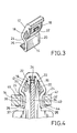
- FIG. 3 is a perspective view of the fastener cut in half;
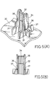
- FIG. 4 is an elevational view of the fastener in use;
- FIG. 5(A) is a fragmentary perspective view of a cluster showing an insertion rib thereof;
- FIG. 5(B) is an elevational view of the insertion rib;
- FIG. 6 is an elevational view of a fastener according to a second embodiment of the present invention;
- FIG. 7 is a perspective view of the fastener;
- FIG. 8 is an elevational view of the fastener in use;
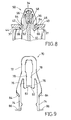
- FIG. 9 is an elevational view of a fastener according to a third embodiment of the present invention;
- FIG. 10 is a perspective view of the fastener;
- FIG. 11 is an elevational view of the fastener in use;
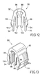
- FIG. 12 is an elevational view of a fastener according to a fourth embodiment of the present invention;
- FIG. 13 is a perspective view of the fastener;
- FIG. 14 is an elevational view of the fastener in use;
and - FIG. 15 is an elevational view of a conventional fastener in use.
-
- Exemplary embodiments of the present invention will be described in detail with reference to the drawings. It should be noted, however, that the present invention is not limited to the following embodiments.
- A first embodiment of the present invention will now be described with reference to FIGS. 1 to 5(B).
- As shown in FIGS. 1 to 3, a
fastener 10 is integrally formed by injection molding of resin. Thefastener 10 is mainly constituted of a substantially inverted V-shaped fastener body 12 having end portions, a pair ofopposed legs 14 provided on the end portions of thefastener body 12, and a pair ofopposed gripper tongues 16 as a gripper portion provided on an inner surface of thefastener body 12. - The
gripper tongues 16 include a pair offlattened gripper surfaces 18 disposed in substantially parallel opposed relation and are dimensioned such that the distance between thegripper surfaces 18 is slightly smaller than the thickness of an insertion rib of a cluster (which will be hereinafter described). Thegripper tongues 16 are provided with a pair of outwardly extendingguide lips 20. As will be appreciated, theguide lips 20 may act as a guide member to reliably introduce the insertion rib of the cluster into a space between the gripper surfaces 18. Moreover, eachgripper surface 18 is provided with anengagement projection 22. Theengagement projection 22 is arranged in the middle of thegripper surface 18 and includes an inclined leading surface so that the insertion rib of the cluster is easily introduced into the space between the gripper surfaces 18. It is to be noted thatgripper tongues 16 can be spread to broaden the space between the gripper surfaces 18 since thegripper tongues 16 are deformable because of its elasticity. - The
fastener body 12 has a pair of opposedouter shoulder portions 24 which extend along juncture portions of thefastener body 12 and thelegs 14. Further, eachleg 14 is provided with astabilizer lip 26 which is outwardly projected from the free end thereof. As will be easily understood, theouter shoulder portions 24 and thelegs 14 can be displaced outwardly and inwardly (laterally as viewed in FIG. 1) since thefastener body 12 has elastic deformability. Additionally, thestabilizer lip 26 can be deformed upwardly and downwardly (vertically as viewed in FIG. 1) because of its elasticity. - Referring to FIGS. 5(A) and 5(B), partly shown therein is a
cluster 30 as a mounting object which is to be mounted on an instrument panel (which will be hereinafter described) by thefastener 10. Thecluster 30 is integrally formed with a plurality of the insertion ribs 32 (one of which is shown for illustration purposes) to which thefastener 10 is to be applied. Thecluster 30 is also provided with a pair of plate-like projections 36 between which theinsertion rib 32 is retained. Theinsertion rib 32 has a transversely elongatedthin slot 34 which is dimensioned to be engageable with theengagement projections 22 of thegripper tongues 16 of thefastener 10. Additionally, eachprojection 36 includes a pair of shouldered seating surfaces 37. - The operation of the
fastener 10 thus constructed will now be described in connection with the process for mounting the cluster onto the instrument panel as a support body. - As shown in FIG. 4, the
fastener 10 is pressed to theinsertion rib 32 of thecluster 30, with the forward end of theinsertion rib 32 positioned between theguide lips 20 of thegripper tongues 16. As a result, therib 32 is introduced into the space between the gripper surfaces 18 of thegripper tongues 16 while spreading thegripper tongues 16. When therib 32 is sufficiently inserted into the space, the gripper surfaces 18 squeezingly contact both side surfaces of therib 32, and simultaneously, theengagement projections 22 formed on thegripper tongues 16 engage thethin slot 34 of therib 32. Thus, thefastener 10 is previously and stably fitted to theinsertion rib 32 of thecluster 30. - Thereafter, the
insertion rib 32 of thecluster 30 with thefastener 10 is pressed into a mountingaperture 42 formed on theinstrument panel 40, so that thefastener 10 fitted to theinsertion rib 32 is inserted into the mountingaperture 42 of theinstrument panel 40 while inwardly flexing thefastener body 12. At this time, theouter shoulder portions 24 of thefastener body 12 elastically engage aninner edge 46 of the mountingaperture 42, and simultaneously, thestabilizer lips 26 elastically engage anouter surface 44 of theinstrument panel 40. As a result, theinsertion rib 32 of thecluster 30 is fixed in the mountingaperture 42 of theinstrument panel 40 by thefastener 10. Thus, thecluster 30 is removably mounted on theinstrument panel 40. - It is to be noted that the
fastener 10, when fitted to theinsertion rib 32 of thecluster 30, cannot easily incline or loosen since thegripper tongues 16 of thefastener 10 is sufficiently stabilized on theinsertion rib 32. This is because eachgripper tongue 16 provides a large area of contact with theinsertion rib 32. Therefore, theinsertion rib 32 of thecluster 30 with thefastener 10 can be easily pressed into the mountingaperture 42 formed on theinstrument panel 40. This may eliminate troublesome work to mount thecluster 30 onto theinstrument panel 40. Moreover, thefastener 10 can be effectively prevented from accidentally falling off from theinsertion rib 32 during handling of thecluster 30. - Additionally, the
stabilizer lips 26 elastically engage theouter surface 44 of theinstrument panel 40, thereby stabilizing thefastener 10 in the mountingaperture 42. Therefore, thefastener 10 permits steady mounting of thecluster 30 on theinstrument panel 40 if there is a variation in thickness of theinstrument panel 40. This is because thestabilizer lips 26 may compensate for the differences of the thickness to properly engage theouter surface 44 of theinstrument panel 40. - To remove the
cluster 30 from theinstrument panel 40 for maintenance or other purposes, thecluster 30 may be simply pulled. When thecluster 30 is pulled, thefastener body 12 of thefastener 10 is inwardly flexed to disengage theouter shoulder portions 24 of thefastener body 12 from theinner edge 46 of the mountingaperture 42, so that theinsertion rib 32 of thecluster 30 is pulled out from the mountingaperture 42. Thus, thecluster 30 is removed from theinstrument panel 40. - It should be noted that the
cluster 30 can be removed from theinstrument panel 40, with thefastener 10 fitted to theinsertion rib 32 of thecluster 30. This is because thefastener 10 is reliably fitted to theinsertion rib 32. As a result, thecluster 30 can be remounted on theinstrument panel 40 without any additional work. - A second embodiment of the present invention modified from the first embodiment will now be described with reference to FIGS. 6 to 8, wherein constructions and operation identical with or similar to those of the first embodiment will not be explained.
- As shown in FIGS. 6 and 7, a
fastener 50 is mainly constituted of a substantially inverted V-shapedfastener body 52 having end portions, a pair ofopposed legs 54 provided on the end portions of thefastener body 52, and a pair ofopposed gripper tongues 56 provided on the inner surface of thefastener body 52. - The
gripper tongues 56 include a pair of gripper surfaces 58 disposed in substantially parallel opposed relation. As will be apparent from the drawings, eachgripper surface 58 has a surface area greater than that of thegripper surface 18 in the first embodiment. Eachgripper surface 58 is also provided with anengagement projection 62. Theengagement projection 62 is arranged in the distal end of thegripper surface 58 and has an inclined leading surface. - The
fastener body 52 has a pair of opposed thickened portions which extend along juncture portions of thefastener body 52 and thelegs 54, thereby forming a pair of opposedouter shoulder portions 64 extending therealong. Further, eachleg 54 is provided with astabilizer lip 66 which is outwardly projected from the free end thereof. - The operation of the
fastener 50 thus constructed will now be described in connection with the process for mounting a cluster (which is the same cluster as in the first embodiment) onto an instrument panel (which is the same instrument panel as in the first embodiment). - As shown in FIG. 8, like the
fastener 10 in the first embodiment, thefastener 50 is pressed to theinsertion rib 32 of thecluster 30. As a result, therib 32 is introduced into a space between the gripper surfaces 58 of thegripper tongues 56. When therib 32 is sufficiently inserted into the space, the gripper surfaces 58 squeezingly contact the both side surfaces of therib 32, and simultaneously, theengagement projections 62 formed on thegripper tongues 56 engage thethin slot 34 of therib 32. Thus, thefastener 50 is previously and stably fitted to theinsertion rib 32 of thecluster 30. - Thereafter, the
insertion rib 32 of thecluster 30 with thefastener 50 is pressed into the mountingaperture 42 formed on theinstrument panel 40, so that thefastener 50 fitted to theinsertion rib 32 is inserted into the mountingaperture 42. At this time, theshoulder portions 64 of thefastener body 52 elastically engage theinner edge 46 of the mountingaperture 42, and simultaneously, thestabilizer lips 66 elastically engage theouter surface 44 of theinstrument panel 40. As a result, theinsertion rib 32 of thecluster 30 is fixed in the mountingaperture 42 of theinstrument panel 40 by thefastener 50. Thus, thecluster 30 is removably mounted on theinstrument panel 40. - A third embodiment of the present invention modified from the second embodiment will now be described with reference to FIGS. 9 to 11, wherein constructions and operation identical with or similar to those of the second embodiment will not be explained.
- As shown in FIGS. 9 and 10, a
fastener 70 is mainly constituted of a substantially inverted V-shapedfastener body 72 having end portions, a pair ofopposed legs 74 provided on the end portions of thefastener body 72, and a pair ofopposed gripper tongues 76 provided on the inner surface of thefastener body 72. As will be apparent from the drawings, thefastener 70 has a length greater than that of thefastener 50 of the second embodiment. - The
gripper tongues 76 include a pair of gripper surfaces 78 disposed in substantially parallel opposed relation. Eachgripper surface 78 is also provided with anengagement projection 82. Theengagement projection 82 is arranged in the distal end of thegripper surface 78 and has an inclined leading surface. - The
fastener body 72 has a pair of opposed thickened portions which extend along juncture portions of thefastener body 72 and thelegs 74, thereby forming a pair of opposedouter shoulder portions 84 extending therealong. Further, eachleg 74 is provided with astabilizer lip 86 which is outwardly projected from the free end thereof. - The operation of the
fastener 70 thus constructed will now be described in connection with the process for mounting a cluster (which is the same cluster as in the first embodiment) onto an instrument panel (which is the same instrument panel as in the first embodiment). - As shown in FIG. 11, like the
fastener 50 in the second embodiment, thefastener 70 is pressed to theinsertion rib 32 of thecluster 30. As a result, therib 32 is introduced into a space between the gripper surfaces 78 of thegripper tongues 76. When therib 32 is sufficiently inserted into the space, the gripper surfaces 78 squeezingly contact the both side surfaces of therib 32, and simultaneously, theengagement projections 82 formed on thegripper tongues 76 engage thethin slot 34 of therib 32. Thus, thefastener 70 is previously and stably fitted to theinsertion rib 32 of thecluster 30. - Thereafter, the
insertion rib 32 of thecluster 30 with thefastener 70 is pressed into the mountingaperture 42 formed on theinstrument panel 40 until the seating surfaces 37 of thecluster 30 contact theouter surface 44 of theinstrument panel 40. At this time, thefastener 70 is inserted into the mountingaperture 42 with theinsertion rib 32, so that theshoulder portions 84 of thefastener body 72 elastically engage theinner edge 46 of the mountingaperture 42. As a result, theinsertion rib 32 of thecluster 30 is fixed in the mountingaperture 42 of theinstrument panel 40 by thefastener 70, with theseating surface 37 urged to theouter surface 44 of theinstrument panel 40. Thus, thecluster 30 is removably mounted on theinstrument panel 40. - As will be apparent from FIG. 11, in this embodiment, the
stabilizer lips 86 does not engage theouter surface 44 of theinstrument panel 40. Therefore, thestabilizer lips 86 can be eliminated from thelegs 74. In contrast, thestabilizer lips 86 can be dimensionally modified to effectively engage theouter surface 44 of theinstrument panel 40, so as to increase stabilizing performance of thecluster 30 on theinstrument panel 40. - A fourth embodiment of the present invention modified from the second embodiment will now be described with reference to FIGS. 12 to 14, wherein constructions and operation identical with or similar to those of the second embodiment will not be explained.
- As shown in FIGS. 12 and 13, a
fastener 90 is mainly constituted of a substantially inverted V-shapedfastener body 92 having end portions, a pair ofopposed legs 94 provided on the end portions of thefastener body 92, and a pair ofopposed gripper tongues 96 provided on the inner surface of thefastener body 92. As will be apparent from the drawings, thefastener 90 has a rounded outer shape which is somewhat different from the outer shape of thefastener 50 of the second embodiment. - The
gripper tongues 96 include a pair of gripper surfaces 98 disposed in substantially parallel opposed relation. Eachgripper surface 98 is also provided with anengagement projection 102. Theengagement projection 102 is arranged in the distal end of thegripper surface 98 and has an inclined leading surface. - The
fastener body 92 has a pair of opposed thickened portions which extend along juncture portions of thefastener body 92 and thelegs 94, thereby forming a pair of opposedouter shoulder portions 104 extending therealong. - The operation of the
fastener 90 thus constructed will now be described in connection with the process for mounting a cluster (which is the same cluster as in the first embodiment) onto an instrument panel (which is the same instrument panel as in the first embodiment). - As shown in FIG. 14, like the
fastener 50 in the second embodiment, thefastener 90 is pressed to theinsertion rib 32 of thecluster 30. As a result, therib 32 is introduced into a space between the gripper surfaces 98 of thegripper tongues 96. When therib 32 is sufficiently inserted into the space, the gripper surfaces 98 squeezingly contact the both side surfaces of therib 32, and simultaneously, theengagement projections 102 formed on thegripper tongues 96 engage thethin slot 34 of therib 32. Thus, thefastener 90 is previously and stably fitted to theinsertion rib 32 of thecluster 30. - Thereafter, the
insertion rib 32 of thecluster 30 with thefastener 90 is pressed into the mountingaperture 42 formed on theinstrument panel 40 until the seating surfaces 37 of thecluster 30 contact theouter surface 44 of theinstrument panel 40. At this time, thefastener 90 is inserted into the mountingaperture 42 with theinsertion rib 32, so that theshoulder portions 104 of thefastener body 90 elastically engage theinner edge 46 of the mountingaperture 42. As a result, theinsertion rib 32 of thecluster 30 is fixed in the mountingaperture 42 of theinstrument panel 40 by thefastener 90, with theseating surface 37 urged to theouter surface 44 of theinstrument panel 40. Thus, thecluster 30 is removably mounted on theinstrument panel 40. - As will be apparent from the drawings, in this embodiment, no stabilizer lip is provided on the
engagement lips 94. However, theengagement lips 94 can be provided with stabilizer lips to engage theouter surface 44 of theinstrument panel 40, so as to increase stabilizing performance of thecluster 30 on theinstrument panel 40. - Although in the above preferred embodiments, the fastener is used to mount the cluster onto the instrument panel, such a fastener may be used for many applications, for example, to mount a garnish, a molding and like members onto an automobile body. Additionally, the fastener may have various configurations, depending on the purposes.
- The preferred embodiments herein described are intended to be illustrative of the invention and not to limit the invention to the precise form herein described. They are chosen and described to explain the principles of the invention and their application and practical use to enable others skilled in the art to practice the invention.
Claims (7)
- A fastener for use for mounting a mounting object having an insertion rib (32) onto a support body (40) having a mounting aperture (42), in use the fastener being previously fitted to the insertion rib (32) of the mounting object (30) and then inserted into the mounting aperture (42) of the support body (40) by pressing the insertion rib (32) thereinto, thereby removably mounting the mounting object (30) on the support body (40), the fastener comprising:a fastener body (12) having a shoulder portion (24), said shoulder portion (24) being adapted to elastically engage an inner edge of the mounting aperture (42) of the support body (40) when the fastener is inserted into the mounting aperture (42) with the insertion rib (32); anda gripper portion (16) provided on said fastener body and having at least one gripper surface (18) and at least one engagement projection (22) formed thereon, said at least one gripper surface (18) being adapted to contact the insertion rib (32) of the mounting object (30) when the fastener is fitted to the insertion rib (32), said at least one engagement projection (22) being adapted to engage a slot (34) formed in the insertion rib (32) of the mounting object (30) when the fastener is fitted to the insertion rib (32).
- A fastener according to claim 1 further comprising at least one stabilizer (26) provided on said fastener body (12), said stabilizer (26) being adapted to elastically engage an outer surface (44) of the support body (40) when the fastener is inserted into the mounting aperture (42) of the support body (40) with the insertion rib (32).
- A fastener according to claim 1 or 2, wherein said fastener body (12) is dimensioned such that said shoulder portion (24) engages the inner edge of the mounting aperture (42) of the support body (40) when the insertion rib (32) of the mounting object (30) is pressed into the mounting aperture (42) of the support body (40) until a seating surface (37) formed on the mounting object (30) contacts an outer surface of the support body (40).
- A fastener according to claim 1, 2 or 3, wherein said fastener body (12) has a substantially V-shaped configuration, and wherein said gripper portion (16) comprises a pair of opposed gripper tongues (16) integrally formed on an inner surface of said fastener body (12).
- A fastener according to claim 4, wherein said at least one gripper surface comprises a pair of flattened surfaces (18) formed on said opposed gripper tongues (16) and disposed in substantially parallel opposed relation, said opposed flattened surfaces (18) squeezingly contacting both side surfaces of the insertion rib (32) of the mounting object when the fastener is fitted to the insertion rib (32).
- A fastener according to claim 4 or 5, wherein each of said gripper tongues (16) is provided with a guide lip (20) for guiding the insertion rib (32) of the mounting object (30).
- A method of mounting a mounting object (30) having an insertion rib (32) into a support body (40) having a mounting aperture (42), the method comprising the steps of:providing a fastener according to any one of the preceding claims;fitting the fastener in the insertion rib (32) of said mounting object (30), and;pressing the insertion rib (32) into the mounting aperture (42) of said support body (40).
Applications Claiming Priority (6)
| Application Number | Priority Date | Filing Date | Title |
|---|---|---|---|
| JP14003096 | 1996-06-03 | ||
| JP140030/96 | 1996-06-03 | ||
| JP14003096 | 1996-06-03 | ||
| JP9066612A JPH1054411A (en) | 1996-06-03 | 1997-03-19 | Clip |
| JP6661297 | 1997-03-19 | ||
| JP66612/97 | 1997-03-19 |
Publications (2)
| Publication Number | Publication Date |
|---|---|
| EP0814273A1 EP0814273A1 (en) | 1997-12-29 |
| EP0814273B1 true EP0814273B1 (en) | 2000-05-03 |
Family
ID=26407809
Family Applications (1)
| Application Number | Title | Priority Date | Filing Date |
|---|---|---|---|
| EP97303726A Expired - Lifetime EP0814273B1 (en) | 1996-06-03 | 1997-06-02 | A fastener |
Country Status (8)
| Country | Link |
|---|---|
| US (3) | US5966782A (en) |
| EP (1) | EP0814273B1 (en) |
| JP (1) | JPH1054411A (en) |
| CN (1) | CN1070585C (en) |
| CA (1) | CA2206681C (en) |
| DE (1) | DE69701836T2 (en) |
| ES (1) | ES2149551T3 (en) |
| PT (1) | PT814273E (en) |
Families Citing this family (85)
| Publication number | Priority date | Publication date | Assignee | Title |
|---|---|---|---|---|
| WO1998033679A2 (en) * | 1997-01-31 | 1998-08-06 | Mecano Rapid Gmbh | Fixing element |
| DE69921800T2 (en) * | 1999-08-04 | 2005-11-24 | Piolax Inc., Yokohama | Mounting structure with U-shaped bracket |
| US6517300B2 (en) * | 2000-02-22 | 2003-02-11 | Pem Management, Inc. | Rectangular hole snap-in fastener |
| BR0010884A (en) * | 2000-03-24 | 2002-02-19 | Antolin Grupo Ing Sa | Metaloplastic clamp for fixing roofs and vehicle accessories to the vehicle body |
| US7361185B2 (en) * | 2001-05-09 | 2008-04-22 | Canica Design, Inc. | Clinical and surgical system and method for moving and stretching plastic tissue |
| JP4657419B2 (en) * | 2000-05-22 | 2011-03-23 | 株式会社ニフコ | clip |
| JP2002021823A (en) * | 2000-07-04 | 2002-01-23 | Nifco Inc | Plate material fitting structure |
| DE10040757C1 (en) * | 2000-08-19 | 2001-09-27 | Raymond A & Cie | Retaining clip, for fastening component to bolt with longitudinal grooves, comprises socket with retaining strips and flexible arm which is pushed up by bolt so that its free end lodges against a projection under socket top |
| JP3699048B2 (en) * | 2001-02-01 | 2005-09-28 | ハン イル エ ワ カンパニーリミテッド | Goods mounting clip |
| JP2004519628A (en) | 2001-03-02 | 2004-07-02 | ニューフレイ リミテッド ライアビリティ カンパニー | U-shaped base fastener with low insertion force |
| US11440486B2 (en) * | 2012-05-21 | 2022-09-13 | Termax Llc | Fastener clip with stabilizing shoulder tabs |
| US8627552B2 (en) * | 2001-06-25 | 2014-01-14 | Termax Corporation | Multicontact adaptive fastener clip |
| US6449814B1 (en) * | 2001-09-13 | 2002-09-17 | Summit Polymers, Inc. | Trim fastener clip employing multiple lines-of-contact stabilization |
| JP4227741B2 (en) | 2001-10-29 | 2009-02-18 | 株式会社ニフコ | clip |
| US6671934B2 (en) | 2002-02-01 | 2004-01-06 | Intier Automotive Inc. | Retention clip |
| US6796006B2 (en) | 2002-04-25 | 2004-09-28 | Illinois Tool Works Inc. | Rib clip |
| US6908275B2 (en) | 2002-04-29 | 2005-06-21 | Charles Nelson | Fastener having supplemental support and retention capabilities |
| US6668429B2 (en) * | 2002-05-03 | 2003-12-30 | Ykk Corporation Of America | Deep-groove fastener |
| EP1507981A1 (en) * | 2002-05-28 | 2005-02-23 | Newfrey LLC | Resilient clip fastener and method of manufacturing the same |
| KR20050008111A (en) * | 2003-07-14 | 2005-01-21 | 현대모비스 주식회사 | Structure For Assembling The Crash Pad The Motors |
| JP2005098437A (en) * | 2003-09-26 | 2005-04-14 | Tokai Kogyo Co Ltd | Molding assembly and mounting tool |
| US6974292B2 (en) * | 2003-10-30 | 2005-12-13 | Illinois Tool Works Inc | One-piece reusable plastic fastener |
| JP4179986B2 (en) * | 2003-12-26 | 2008-11-12 | サクラ工業株式会社 | CORE PIECE OF EXHAUST CATALYST DEVICE, ITS MANUFACTURING METHOD, AND INSERTION AND FIXING METHOD THEREOF |
| US20050238414A1 (en) * | 2004-04-16 | 2005-10-27 | General Binding Corporation | Disposable clip for coupling binding elements and combination of binding elements with disposable coupling clip |
| EP2250988A3 (en) | 2004-04-30 | 2011-11-30 | Hill-Rom Services, Inc. | Patient support with motion monitor device |
| EP1647480B1 (en) * | 2004-10-13 | 2010-12-08 | Airbus Operations GmbH | Joint covering for aircraft |
| US7461436B2 (en) * | 2004-10-26 | 2008-12-09 | Piolax, Inc. | Mounting structure of vehicle interior material |
| US20060099051A1 (en) * | 2004-11-05 | 2006-05-11 | Moerke Benjamin H | Sealing fastener |
| DE102005023767A1 (en) * | 2005-05-19 | 2006-11-23 | Otto-Von-Guericke-Universität Magdeburg | Electrostrictive actuator for valve is mounted between legs of bent lift arm by draw elements |
| KR100970986B1 (en) * | 2005-06-08 | 2010-07-20 | 한국 티알더블류 자동차부품산업 주식회사 | Plastic fastner |
| US7401388B2 (en) * | 2005-09-06 | 2008-07-22 | Illinois Tool Works Inc. | Rib clip |
| DE502007002527D1 (en) * | 2006-05-30 | 2010-02-25 | Ford Werke Gmbh | mounting clip |
| WO2008082252A1 (en) * | 2007-01-05 | 2008-07-10 | Lg Electronics Inc. | Refrigerator |
| KR101413318B1 (en) * | 2007-01-12 | 2014-06-27 | 엘지전자 주식회사 | A coupling unit |
| DE102007015129B3 (en) * | 2007-03-29 | 2008-08-28 | Itw Automotive Products Gmbh & Co. Kg | Non-removable plastic clip for use during manufacture of automobile, has supporting surface extending close to free end of arm section, such that free end cooperates with surface, when extraction force is applied on clip |
| US7600809B2 (en) * | 2007-10-19 | 2009-10-13 | Honda Motor Co., Ltd. | Clip tower for energy absorption |
| US20090113677A1 (en) * | 2007-11-02 | 2009-05-07 | Marketing Displays Inc. | Sliding Member Bollard Bracket |
| JP4788706B2 (en) * | 2007-11-16 | 2011-10-05 | 豊田合成株式会社 | Parts mounting structure |
| US20100006163A1 (en) * | 2008-01-25 | 2010-01-14 | Vitec. LLC | Fuel System and Method for Assembling the Same |
| WO2009099664A1 (en) * | 2008-02-07 | 2009-08-13 | Tinnerman Palnut Engineered Products | Deck clip |
| FR2930976B1 (en) * | 2008-05-07 | 2013-06-21 | Raymond A & Cie | FASTENING CLAMP OF TWO PIECES ON ONE ANOTHER |
| JP5091775B2 (en) * | 2008-06-16 | 2012-12-05 | 株式会社ニフコ | Connector |
| JP4540726B2 (en) * | 2008-07-04 | 2010-09-08 | 大和化成工業株式会社 | Two-part assembly structure |
| EP2175146A3 (en) * | 2008-10-10 | 2012-01-25 | Newfrey LLC | Fastener and fastener assembly |
| US20100115878A1 (en) * | 2008-11-10 | 2010-05-13 | Anatoly Gosis | Spring bracket for framing stud installation |
| US20110225778A1 (en) * | 2010-03-18 | 2011-09-22 | Newfrey Llc | Interior trim sealing fastener |
| JP5558322B2 (en) * | 2010-11-25 | 2014-07-23 | 大和化成工業株式会社 | clip |
| JP5714317B2 (en) * | 2010-12-24 | 2015-05-07 | 大和化成工業株式会社 | Spring clip |
| KR20120094653A (en) * | 2011-02-17 | 2012-08-27 | 주식회사 니프코코리아 | A plastic clip |
| DE102011012406A1 (en) * | 2011-02-25 | 2012-08-30 | Webasto Ag | Bracket for mounting handle and fan bar in recess of sliding roof lining carrier of vehicle, comprises base section and latch arm, which is integrally formed with base section |
| US8858120B2 (en) * | 2011-07-14 | 2014-10-14 | Vicwest Inc. | Liquid containment system |
| JP2013083294A (en) * | 2011-10-07 | 2013-05-09 | Kojima Press Industry Co Ltd | Installing structure of member to be attached |
| JP5487230B2 (en) * | 2012-03-21 | 2014-05-07 | 東芝テック株式会社 | Component support device and inkjet device |
| JP5964735B2 (en) * | 2012-11-28 | 2016-08-03 | 株式会社ニフコ | clip |
| US9879779B2 (en) * | 2013-03-08 | 2018-01-30 | Denso International America, Inc. | Self-retaining gasket |
| US9046178B2 (en) * | 2013-03-08 | 2015-06-02 | Denso International America, Inc. | Self-retaining gasket and fastener retainer |
| CN103615301B (en) * | 2013-12-11 | 2016-03-30 | 重庆长安汽车股份有限公司 | A kind of automotive muffler erecting by overhang |
| US20150164184A1 (en) * | 2013-12-17 | 2015-06-18 | GM Global Technology Operations LLC | Fastener for operatively coupling matable components |
| TWI590737B (en) * | 2014-01-08 | 2017-07-01 | 緯創資通股份有限公司 | Combining member and device having the same |
| US20150211565A1 (en) * | 2014-01-27 | 2015-07-30 | Newfrey Llc | Plastic u-base fastener with noise control feature |
| BR112016028669A2 (en) * | 2014-06-12 | 2017-08-22 | Illinois Tool Works | clip mount |
| JP1518019S (en) * | 2014-08-05 | 2015-02-23 | ||
| US20160066678A1 (en) * | 2014-09-05 | 2016-03-10 | Filip Technologies, Inc. | Band support structure for wearable device |
| US9657759B2 (en) | 2014-09-10 | 2017-05-23 | Newfrey Llc | U-based fastener with improved rib attachment |
| FR3027640B1 (en) * | 2014-10-24 | 2017-04-21 | Peugeot Citroen Automobiles Sa | ARRANGEMENT OF A STRUCTURE FOR MOUNTING A PIECE IN AN IRREGULAR CONTOUR OPENING |
| WO2017021427A1 (en) * | 2015-08-03 | 2017-02-09 | Johnson Controls Gmbh | Stop for a rail of a longitudinally adjustable seat |
| CN105414499B (en) * | 2015-12-08 | 2017-09-08 | 重庆盛镁镁业有限公司 | Swollen cassette aluminium alloy connection component |
| CN105605047A (en) * | 2016-03-07 | 2016-05-25 | 上海球明标准件有限公司 | Metal fixing clamp for fastening mounting members |
| CN106015245B (en) * | 2016-06-29 | 2018-02-23 | 上海球明标准件有限公司 | A kind of metallic elastic link block for the installation of automotive trim plastic plate |
| CN106001975A (en) * | 2016-07-19 | 2016-10-12 | 苏州誉衡昌精密机械有限公司 | Novel automatically positioned stamping part |
| JP6409044B2 (en) * | 2016-12-28 | 2018-10-17 | 株式会社ニフコ | Member mounting structure and mounting clip |
| EP3413688B1 (en) | 2017-06-09 | 2021-08-11 | Electrolux Appliances Aktiebolag | Connecting element for connecting an induction coil to a coil carrier of an induction cooking hob |
| CN107269638A (en) * | 2017-06-12 | 2017-10-20 | 武城县光明电力工程有限公司 | A kind of electric power anchor ear device |
| CN110799065B (en) * | 2017-06-28 | 2021-10-26 | 利纳克有限公司 | Linear actuator |
| DE102017129298A1 (en) * | 2017-12-08 | 2019-06-13 | Khs Gmbh | transport device |
| CN207961202U (en) * | 2018-01-08 | 2018-10-12 | 福特环球技术公司 | Sub- part and part assemblies |
| CN108944721A (en) * | 2018-08-02 | 2018-12-07 | 安徽江淮汽车集团股份有限公司 | Trim panel clamping structure |
| CN109278503A (en) * | 2018-11-29 | 2019-01-29 | 安徽江淮汽车集团股份有限公司 | A kind of car side window sunshade curtain assembly |
| EP3670937B1 (en) * | 2018-12-18 | 2023-03-22 | Volvo Car Corporation | A retaining clip for connecting components |
| USD876207S1 (en) * | 2019-01-14 | 2020-02-25 | Wanho T Manufacturing Co., Ltd. | Cable retainer device |
| USD876933S1 (en) * | 2019-01-14 | 2020-03-03 | Wanho T Manufacturing Co., Ltd. | Cable retainer device |
| US11149774B2 (en) * | 2019-10-03 | 2021-10-19 | Newfrey Llc | Bathtub fastener assembly |
| USD934063S1 (en) * | 2020-01-20 | 2021-10-26 | Illinois Tool Works Inc. | Fastening clip |
| CN114930037A (en) | 2020-01-17 | 2022-08-19 | 伊利诺斯工具制品有限公司 | Metal retaining clip |
| CN111997981A (en) * | 2020-08-24 | 2020-11-27 | 广东百能堡科技有限公司 | Buckle of convenient loading and unloading |
Family Cites Families (19)
| Publication number | Priority date | Publication date | Assignee | Title |
|---|---|---|---|---|
| US3197935A (en) * | 1961-10-05 | 1965-08-03 | Ford Motor Co | Trim molding fastener |
| GB1036424A (en) * | 1961-10-13 | 1966-07-20 | Ft Products Ltd | An improved fastener |
| GB1012122A (en) * | 1962-03-22 | 1965-12-08 | Ft Products Ltd | Improvements in and relating to fasteners |
| GB1004798A (en) * | 1962-09-27 | 1965-09-15 | Albert Victor Raymond | An improved moulding clip |
| JPS5018049Y2 (en) * | 1971-09-13 | 1975-06-03 | ||
| JPS5836209B2 (en) * | 1978-10-30 | 1983-08-08 | 豊田合成株式会社 | Mounting structure for two objects |
| JPS5934732Y2 (en) * | 1980-11-05 | 1984-09-26 | 株式会社ニフコ | Parts mounting structure |
| US4402118A (en) * | 1981-09-28 | 1983-09-06 | Usm Corporation | Clip for securing a panel to a support |
| JPS61138746A (en) * | 1984-12-04 | 1986-06-26 | 津田駒工業株式会社 | Disc spray weft yarn storage apparatus for fluid jet type shuttleless loom |
| JPH0676804B2 (en) * | 1985-07-15 | 1994-09-28 | 株式会社ニフコ | Fasteners for fastening two panels in a face-to-face manner |
| JPS6277306A (en) * | 1985-09-30 | 1987-04-09 | Kobe Paint Kk | Novel antifouling agent and submarine antifouling coating material using said agent |
| US4644612A (en) * | 1986-05-30 | 1987-02-24 | Usm Corporation | Panel retainer |
| JPS6477111A (en) * | 1987-09-18 | 1989-03-23 | Fujikura Ltd | Removal of static electricity of wafer |
| JP2621087B2 (en) * | 1988-09-12 | 1997-06-18 | マルコン電子株式会社 | Solid electrolytic capacitor and method of manufacturing the same |
| DE9205186U1 (en) * | 1992-04-14 | 1992-06-17 | Emhart Inc., Newark, Del., Us | |
| JPH0649928A (en) | 1992-07-29 | 1994-02-22 | Mitsuwa:Kk | Construction of wall in building and wall panel |
| JP3093082B2 (en) * | 1993-07-20 | 2000-10-03 | トヨタ自動車株式会社 | Vehicle mounting clips |
| JPH07293521A (en) * | 1994-04-27 | 1995-11-07 | Yukie Ueno | Clip for assembling parts |
| US5533237A (en) * | 1994-09-12 | 1996-07-09 | Emhart, Inc. | Grommet fastener assembly for automobiles |
-
1997
- 1997-03-19 JP JP9066612A patent/JPH1054411A/en active Pending
- 1997-06-02 ES ES97303726T patent/ES2149551T3/en not_active Expired - Lifetime
- 1997-06-02 EP EP97303726A patent/EP0814273B1/en not_active Expired - Lifetime
- 1997-06-02 PT PT97303726T patent/PT814273E/en unknown
- 1997-06-02 CN CN97105482A patent/CN1070585C/en not_active Expired - Fee Related
- 1997-06-02 CA CA002206681A patent/CA2206681C/en not_active Expired - Fee Related
- 1997-06-02 DE DE69701836T patent/DE69701836T2/en not_active Expired - Lifetime
- 1997-06-03 US US08/867,971 patent/US5966782A/en not_active Expired - Lifetime
-
1999
- 1999-08-19 US US09/377,243 patent/US6119316A/en not_active Expired - Lifetime
-
2000
- 2000-09-12 US US09/660,547 patent/US6317937B1/en not_active Expired - Lifetime
Also Published As
| Publication number | Publication date |
|---|---|
| CA2206681A1 (en) | 1997-12-03 |
| DE69701836D1 (en) | 2000-06-08 |
| PT814273E (en) | 2000-09-29 |
| EP0814273A1 (en) | 1997-12-29 |
| US6317937B1 (en) | 2001-11-20 |
| CN1070585C (en) | 2001-09-05 |
| ES2149551T3 (en) | 2000-11-01 |
| US5966782A (en) | 1999-10-19 |
| CA2206681C (en) | 2006-03-21 |
| US6119316A (en) | 2000-09-19 |
| DE69701836T2 (en) | 2000-11-02 |
| CN1172913A (en) | 1998-02-11 |
| JPH1054411A (en) | 1998-02-24 |
Similar Documents
| Publication | Publication Date | Title |
|---|---|---|
| EP0814273B1 (en) | A fastener | |
| JPH0322570Y2 (en) | ||
| US6665914B2 (en) | Clip | |
| JPS6323010A (en) | Panel retainer | |
| EP0660018A1 (en) | A tie | |
| JPH11287221A (en) | Clip | |
| JP2006242286A (en) | Clip | |
| JP4219467B2 (en) | clip | |
| US6086021A (en) | Adjustable anti-rotational fastener for wire harness components | |
| JP2000074020A (en) | Mounting equipment for member | |
| JPH0216919Y2 (en) | ||
| JP2816457B2 (en) | Fixture for T-slot | |
| JPH0536770Y2 (en) | ||
| JP3554591B2 (en) | Band clip for mounting long objects | |
| JP4184473B2 (en) | clip | |
| JP2759264B2 (en) | Article mounting structure | |
| JPH0724650Y2 (en) | Retaining clip | |
| JPH06212770A (en) | Vibration-proofing decorative panel | |
| JPH0648167Y2 (en) | Combination connection device | |
| JPH074328Y2 (en) | Two-part fixture | |
| JPH0534328Y2 (en) | ||
| JP3600743B2 (en) | Structural material fixing device | |
| JPH064087Y2 (en) | Retaining clip | |
| JP2002293207A (en) | Part fixing structure | |
| CN117677539A (en) | Cover for bumper opening |
Legal Events
| Date | Code | Title | Description |
|---|---|---|---|
| PUAI | Public reference made under article 153(3) epc to a published international application that has entered the european phase |
Free format text: ORIGINAL CODE: 0009012 |
|
| AK | Designated contracting states |
Kind code of ref document: A1 Designated state(s): CH DE ES FR GB IT LI NL PT SE |
|
| 17P | Request for examination filed |
Effective date: 19980309 |
|
| 17Q | First examination report despatched |
Effective date: 19980520 |
|
| AKX | Designation fees paid |
Free format text: CH DE ES FR GB IT LI NL PT SE |
|
| RBV | Designated contracting states (corrected) |
Designated state(s): CH DE ES FR GB IT LI NL PT SE |
|
| GRAG | Despatch of communication of intention to grant |
Free format text: ORIGINAL CODE: EPIDOS AGRA |
|
| GRAG | Despatch of communication of intention to grant |
Free format text: ORIGINAL CODE: EPIDOS AGRA |
|
| GRAH | Despatch of communication of intention to grant a patent |
Free format text: ORIGINAL CODE: EPIDOS IGRA |
|
| GRAH | Despatch of communication of intention to grant a patent |
Free format text: ORIGINAL CODE: EPIDOS IGRA |
|
| GRAA | (expected) grant |
Free format text: ORIGINAL CODE: 0009210 |
|
| AK | Designated contracting states |
Kind code of ref document: B1 Designated state(s): CH DE ES FR GB IT LI NL PT SE |
|
| REG | Reference to a national code |
Ref country code: CH Ref legal event code: EP |
|
| REG | Reference to a national code |
Ref country code: CH Ref legal event code: NV Representative=s name: NOVAPAT INTERNATIONAL S.A. |
|
| REF | Corresponds to: |
Ref document number: 69701836 Country of ref document: DE Date of ref document: 20000608 |
|
| ITF | It: translation for a ep patent filed |
Owner name: STUDIO GLP S.R.L. |
|
| ET | Fr: translation filed | ||
| REG | Reference to a national code |
Ref country code: PT Ref legal event code: SC4A Free format text: AVAILABILITY OF NATIONAL TRANSLATION Effective date: 20000616 |
|
| REG | Reference to a national code |
Ref country code: ES Ref legal event code: FG2A Ref document number: 2149551 Country of ref document: ES Kind code of ref document: T3 |
|
| PLBE | No opposition filed within time limit |
Free format text: ORIGINAL CODE: 0009261 |
|
| STAA | Information on the status of an ep patent application or granted ep patent |
Free format text: STATUS: NO OPPOSITION FILED WITHIN TIME LIMIT |
|
| 26N | No opposition filed | ||
| REG | Reference to a national code |
Ref country code: GB Ref legal event code: IF02 |
|
| PGFP | Annual fee paid to national office [announced via postgrant information from national office to epo] |
Ref country code: CH Payment date: 20080611 Year of fee payment: 12 |
|
| PGFP | Annual fee paid to national office [announced via postgrant information from national office to epo] |
Ref country code: SE Payment date: 20080609 Year of fee payment: 12 Ref country code: NL Payment date: 20080603 Year of fee payment: 12 |
|
| PGFP | Annual fee paid to national office [announced via postgrant information from national office to epo] |
Ref country code: PT Payment date: 20090529 Year of fee payment: 13 Ref country code: IT Payment date: 20090616 Year of fee payment: 13 |
|
| PGFP | Annual fee paid to national office [announced via postgrant information from national office to epo] |
Ref country code: ES Payment date: 20090709 Year of fee payment: 13 |
|
| REG | Reference to a national code |
Ref country code: CH Ref legal event code: PL |
|
| NLV4 | Nl: lapsed or anulled due to non-payment of the annual fee |
Effective date: 20100101 |
|
| PG25 | Lapsed in a contracting state [announced via postgrant information from national office to epo] |
Ref country code: LI Free format text: LAPSE BECAUSE OF NON-PAYMENT OF DUE FEES Effective date: 20090630 Ref country code: CH Free format text: LAPSE BECAUSE OF NON-PAYMENT OF DUE FEES Effective date: 20090630 |
|
| PG25 | Lapsed in a contracting state [announced via postgrant information from national office to epo] |
Ref country code: NL Free format text: LAPSE BECAUSE OF NON-PAYMENT OF DUE FEES Effective date: 20100101 |
|
| REG | Reference to a national code |
Ref country code: PT Ref legal event code: MM4A Free format text: LAPSE DUE TO NON-PAYMENT OF FEES Effective date: 20101202 |
|
| PG25 | Lapsed in a contracting state [announced via postgrant information from national office to epo] |
Ref country code: PT Free format text: LAPSE BECAUSE OF NON-PAYMENT OF DUE FEES Effective date: 20101202 |
|
| PG25 | Lapsed in a contracting state [announced via postgrant information from national office to epo] |
Ref country code: IT Free format text: LAPSE BECAUSE OF NON-PAYMENT OF DUE FEES Effective date: 20100602 |
|
| PG25 | Lapsed in a contracting state [announced via postgrant information from national office to epo] |
Ref country code: SE Free format text: LAPSE BECAUSE OF NON-PAYMENT OF DUE FEES Effective date: 20090603 |
|
| REG | Reference to a national code |
Ref country code: ES Ref legal event code: FD2A Effective date: 20110715 |
|
| PG25 | Lapsed in a contracting state [announced via postgrant information from national office to epo] |
Ref country code: ES Free format text: LAPSE BECAUSE OF NON-PAYMENT OF DUE FEES Effective date: 20110705 |
|
| PG25 | Lapsed in a contracting state [announced via postgrant information from national office to epo] |
Ref country code: ES Free format text: LAPSE BECAUSE OF NON-PAYMENT OF DUE FEES Effective date: 20100603 |
|
| REG | Reference to a national code |
Ref country code: FR Ref legal event code: PLFP Year of fee payment: 19 |
|
| PGFP | Annual fee paid to national office [announced via postgrant information from national office to epo] |
Ref country code: DE Payment date: 20150527 Year of fee payment: 19 Ref country code: GB Payment date: 20150527 Year of fee payment: 19 |
|
| PGFP | Annual fee paid to national office [announced via postgrant information from national office to epo] |
Ref country code: FR Payment date: 20150608 Year of fee payment: 19 |
|
| REG | Reference to a national code |
Ref country code: DE Ref legal event code: R119 Ref document number: 69701836 Country of ref document: DE |
|
| GBPC | Gb: european patent ceased through non-payment of renewal fee |
Effective date: 20160602 |
|
| REG | Reference to a national code |
Ref country code: FR Ref legal event code: ST Effective date: 20170228 |
|
| PG25 | Lapsed in a contracting state [announced via postgrant information from national office to epo] |
Ref country code: DE Free format text: LAPSE BECAUSE OF NON-PAYMENT OF DUE FEES Effective date: 20170103 Ref country code: FR Free format text: LAPSE BECAUSE OF NON-PAYMENT OF DUE FEES Effective date: 20160630 |
|
| PG25 | Lapsed in a contracting state [announced via postgrant information from national office to epo] |
Ref country code: GB Free format text: LAPSE BECAUSE OF NON-PAYMENT OF DUE FEES Effective date: 20160602 |