EP0814236A1 - Lagerträger, der es erlaubt ein Turbotriebwerk auch nach dem Auftreten einer Unwucht in Betrieb zu halten - Google Patents
Lagerträger, der es erlaubt ein Turbotriebwerk auch nach dem Auftreten einer Unwucht in Betrieb zu halten Download PDFInfo
- Publication number
- EP0814236A1 EP0814236A1 EP97401324A EP97401324A EP0814236A1 EP 0814236 A1 EP0814236 A1 EP 0814236A1 EP 97401324 A EP97401324 A EP 97401324A EP 97401324 A EP97401324 A EP 97401324A EP 0814236 A1 EP0814236 A1 EP 0814236A1
- Authority
- EP
- European Patent Office
- Prior art keywords
- rotor
- bearing
- turbine engine
- bearing support
- unbalance
- Prior art date
- Legal status (The legal status is an assumption and is not a legal conclusion. Google has not performed a legal analysis and makes no representation as to the accuracy of the status listed.)
- Granted
Links
Images

Classifications
-
- F—MECHANICAL ENGINEERING; LIGHTING; HEATING; WEAPONS; BLASTING
- F01—MACHINES OR ENGINES IN GENERAL; ENGINE PLANTS IN GENERAL; STEAM ENGINES
- F01D—NON-POSITIVE DISPLACEMENT MACHINES OR ENGINES, e.g. STEAM TURBINES
- F01D25/00—Component parts, details, or accessories, not provided for in, or of interest apart from, other groups
- F01D25/16—Arrangement of bearings; Supporting or mounting bearings in casings
- F01D25/162—Bearing supports
-
- F—MECHANICAL ENGINEERING; LIGHTING; HEATING; WEAPONS; BLASTING
- F01—MACHINES OR ENGINES IN GENERAL; ENGINE PLANTS IN GENERAL; STEAM ENGINES
- F01D—NON-POSITIVE DISPLACEMENT MACHINES OR ENGINES, e.g. STEAM TURBINES
- F01D21/00—Shutting-down of machines or engines, e.g. in emergency; Regulating, controlling, or safety means not otherwise provided for
- F01D21/04—Shutting-down of machines or engines, e.g. in emergency; Regulating, controlling, or safety means not otherwise provided for responsive to undesired position of rotor relative to stator or to breaking-off of a part of the rotor, e.g. indicating such position
- F01D21/045—Shutting-down of machines or engines, e.g. in emergency; Regulating, controlling, or safety means not otherwise provided for responsive to undesired position of rotor relative to stator or to breaking-off of a part of the rotor, e.g. indicating such position special arrangements in stators or in rotors dealing with breaking-off of part of rotor
-
- F—MECHANICAL ENGINEERING; LIGHTING; HEATING; WEAPONS; BLASTING
- F01—MACHINES OR ENGINES IN GENERAL; ENGINE PLANTS IN GENERAL; STEAM ENGINES
- F01D—NON-POSITIVE DISPLACEMENT MACHINES OR ENGINES, e.g. STEAM TURBINES
- F01D25/00—Component parts, details, or accessories, not provided for in, or of interest apart from, other groups
- F01D25/16—Arrangement of bearings; Supporting or mounting bearings in casings
-
- F—MECHANICAL ENGINEERING; LIGHTING; HEATING; WEAPONS; BLASTING
- F16—ENGINEERING ELEMENTS AND UNITS; GENERAL MEASURES FOR PRODUCING AND MAINTAINING EFFECTIVE FUNCTIONING OF MACHINES OR INSTALLATIONS; THERMAL INSULATION IN GENERAL
- F16C—SHAFTS; FLEXIBLE SHAFTS; ELEMENTS OR CRANKSHAFT MECHANISMS; ROTARY BODIES OTHER THAN GEARING ELEMENTS; BEARINGS
- F16C27/00—Elastic or yielding bearings or bearing supports, for exclusively rotary movement
- F16C27/04—Ball or roller bearings, e.g. with resilient rolling bodies
-
- F—MECHANICAL ENGINEERING; LIGHTING; HEATING; WEAPONS; BLASTING
- F05—INDEXING SCHEMES RELATING TO ENGINES OR PUMPS IN VARIOUS SUBCLASSES OF CLASSES F01-F04
- F05B—INDEXING SCHEME RELATING TO WIND, SPRING, WEIGHT, INERTIA OR LIKE MOTORS, TO MACHINES OR ENGINES FOR LIQUIDS COVERED BY SUBCLASSES F03B, F03D AND F03G
- F05B2260/00—Function
- F05B2260/30—Retaining components in desired mutual position
- F05B2260/301—Retaining bolts or nuts
- F05B2260/3011—Retaining bolts or nuts of the frangible or shear type
-
- F—MECHANICAL ENGINEERING; LIGHTING; HEATING; WEAPONS; BLASTING
- F16—ENGINEERING ELEMENTS AND UNITS; GENERAL MEASURES FOR PRODUCING AND MAINTAINING EFFECTIVE FUNCTIONING OF MACHINES OR INSTALLATIONS; THERMAL INSULATION IN GENERAL
- F16C—SHAFTS; FLEXIBLE SHAFTS; ELEMENTS OR CRANKSHAFT MECHANISMS; ROTARY BODIES OTHER THAN GEARING ELEMENTS; BEARINGS
- F16C19/00—Bearings with rolling contact, for exclusively rotary movement
- F16C19/02—Bearings with rolling contact, for exclusively rotary movement with bearing balls essentially of the same size in one or more circular rows
- F16C19/04—Bearings with rolling contact, for exclusively rotary movement with bearing balls essentially of the same size in one or more circular rows for radial load mainly
- F16C19/06—Bearings with rolling contact, for exclusively rotary movement with bearing balls essentially of the same size in one or more circular rows for radial load mainly with a single row or balls
-
- F—MECHANICAL ENGINEERING; LIGHTING; HEATING; WEAPONS; BLASTING
- F16—ENGINEERING ELEMENTS AND UNITS; GENERAL MEASURES FOR PRODUCING AND MAINTAINING EFFECTIVE FUNCTIONING OF MACHINES OR INSTALLATIONS; THERMAL INSULATION IN GENERAL
- F16C—SHAFTS; FLEXIBLE SHAFTS; ELEMENTS OR CRANKSHAFT MECHANISMS; ROTARY BODIES OTHER THAN GEARING ELEMENTS; BEARINGS
- F16C2360/00—Engines or pumps
- F16C2360/23—Gas turbine engines
-
- Y—GENERAL TAGGING OF NEW TECHNOLOGICAL DEVELOPMENTS; GENERAL TAGGING OF CROSS-SECTIONAL TECHNOLOGIES SPANNING OVER SEVERAL SECTIONS OF THE IPC; TECHNICAL SUBJECTS COVERED BY FORMER USPC CROSS-REFERENCE ART COLLECTIONS [XRACs] AND DIGESTS
- Y02—TECHNOLOGIES OR APPLICATIONS FOR MITIGATION OR ADAPTATION AGAINST CLIMATE CHANGE
- Y02T—CLIMATE CHANGE MITIGATION TECHNOLOGIES RELATED TO TRANSPORTATION
- Y02T50/00—Aeronautics or air transport
- Y02T50/60—Efficient propulsion technologies, e.g. for aircraft
Definitions
- the invention provides a method for keeping a turbine engine for aircraft in degraded operation after the appearance of an accidental unbalance on a rotor caused for example by a fan blade failure under the impact of a foreign body.
- the invention also provides a device consisting of a bearing support specially designed to implement the method.
- An unbalance on a turbine engine rotor for an aircraft in operation causes a centrifugal rotating force which is transmitted to the structure of the turbine engine via the bearings and bearing supports, and from the rotor-stator contact for very strong unbalances, then to the aircraft structure.
- unbalances There are two kinds of unbalances: manufacturing unbalances and accidental unbalances. Manufacturing imbalances are brought to low values, although not negligible, thanks to the care taken in the manufacture of rotors.
- Accidental unbalances are mainly due to ruptured blades. These unbalances can be significant and cause a rotating force which can take very high values requiring an immediate shutdown of the turbine engine, on pain of destruction of the turbine engine structures and of the aircraft.
- a blade break occurs essentially near the ground during the takeoff and landing phases of the aircraft, by the accidental penetration of foreign bodies such as birds into the air intake of the turbine engine. Such an accident requiring the immediate shutdown of the turbine engine can cause the airplane to crash in these circumstances.
- a first problem to be resolved is therefore to keep the turbine engine in operation despite the imbalance caused for example by a blade break, at least for a limited period and with a reduced thrust, the time to land the aircraft.
- Modern turboshaft engines are generally of the so-called “double-flow” type and comprise a first stage of rotating vanes called a "fan” which provides most of the propulsion effort on subsonic turboshaft engines.
- These fan blades are very vulnerable because they are placed at the very front of the turbine engine because they are thin, of large size and held by one end by means of the rotor while the other end at the periphery of the rotor is free. Although breakage usually occurs toward the free end of the blade, the unbalance generated can be significant due to the large size of the blade.
- the unbalance can reach 3 to 4 kg.m produce, taking into account the elasticity of the structure and the resonance phenomena which result from it, a rotating force of the order of 10 5 DaN at 5000 revolutions per minute.
- a second problem is therefore to keep the turbine engine in operation with such an unbalance.
- a vane rotor and in particular a blower inevitably has a manufacturing unbalance which is all the more important as the blower is heavy and of large diameter.
- this unbalance associated with the natural elasticity of the structure of the turbine engine causes a radial and centrifugal rotating force with resonance points corresponding to the natural modes of the rotor + structure assembly, this rotating force causing accelerated fatigue of the bearings and of the motor structure.
- the bearings of the rotor and more particularly its front bearing are usually held by an elastic bearing support which has the main effect of reducing vibrations and reducing the forces transmitted to the structure.
- Patent EP 63 993 discloses such a bearing comprising an elastic element with movement in a radial plane, the elastic element being in the form of an openwork truncated cone forming a squirrel cage, the movement of this elastic element being however limited radially by a rigid element also in the form of a truncated cone.
- the invention provides a method and a device specially designed to implement this method and making it possible to maintain a turbine engine for aircraft in operation at a rotor speed of rotation at least equal to the idle speed in flight V1, this after the appearance of an accidental unbalance on this rotor.
- the invention applies to a turbine engine, the rotor of which is mounted on bearings and has blades at its periphery which move inside a casing, the radial clearance E between the tops of the blades and the inner wall of the housing being usually but not necessarily obscured by an abradable coating. In such a turbine engine, the proper mode of the rotor is greater than V1 in normal operation.
- the turbine engine operates under normal conditions until an accidental unbalance has appeared on the rotor.
- the transition from the normal stiffness level to a low stiffness level of a bearing support in accordance with the invention results in the proper mode of the rotor being lowered at a speed lower than V1, which has the effect of lowering at speeds greater than V1 the rotating force F transmitted by the rotor to the structure of the turbine engine, and the result of allowing the operation of the turbine engine at these speeds.
- bearing support will be that maintaining the fan stage of the turbine engine, this stage being particularly exposed to the impacts of foreign bodies and by repercussion to blade breakage.
- the invention also provides a bearing support making it possible to implement the present method.
- a bearing support comprises N> 1 elastic elements acting in parallel and each connecting the bearing to the structure of the motor, N-1 elastic elements effecting this connection by means of frangible connecting elements, that is to say capable of breaking under the effect of the radial force caused by an unbalance exceeding a predetermined minimum level.
- these elastic elements are concentric in the form of barrels or thin cylindrical or frustoconical walls and connected by their ends on one side to the structure of the motor and on the other side to the bearing. This connection is permanent on one side and frangible on the other for N-1 elements, these elements being arranged axially and being sensitive to rupture under the effect of a shear and tensile stress in a plane radial to the axis of the rotor.
- the present invention should also not be confused with the bearing disclosed by the aforementioned US Patent 4,527,910. Indeed, such a bearing has only one flexible element which remains active in all circumstances, the frangible connections only act on the damping of vibrations. Such a bearing does not make it possible to soften radially the guiding in rotation of the fan and to lower the proper mode of this fan following the appearance of an accidental unbalance, on the contrary of the present invention. In addition, the viscous damping means do not allow the use of this bearing on large turboshaft engines.
- Another advantage of the invention is the maintenance in degraded operation and without additional means of a rigorous axial positioning of the bearing held by a bearing support according to the invention, after rupture of frangible connections, this maintenance being ensured at least by the element elastic itself not comprising a frangible connection.
- the maintenance being carried out without friction, unlike the device disclosed by patent FR 2 463 853, a bearing support according to the invention can be used in cooperation with a bearing with a thrust effect to maintain the axial positioning of the dawn itself and resume the axial thrust to which this shaft is subjected.
- the present invention is therefore well suited to an application to the blower stage of large turboshaft engines, said blower stage journalling on a large bearing with thrust and generally ball bearing effect, this blower stage generating most of the thrust of the turbine engine, said thrust being transmitted to the structure of the turbine engine by said bearing and said bearing support, even in degraded operation.
- Another advantage of the invention is the absence of heat dissipation after rupture of the frangible connections, unlike devices with damping, which avoids having to have additional cooling means on large turboshaft engines.
- Another advantage is the reduction in the risk of rotor / stator interaction due to the increased clearance E, and the resulting reduction in mass gain.
- the present invention also has the advantage, in its preferred embodiment, of using a simple bearing support, inexpensive and having a general shape, a space requirement and means of connection to the bearing and to the structure of the turbine engine very similar to the conventional bearing supports usually used on turbine engines.
- the present invention can therefore be applied to a turbine engine without jeopardizing its structure.
- Figure 1 illustrates a turbine engine fan stage according to the invention.
- Figure 2 is a graph illustrating the elasticity characteristic of a bearing support according to the invention.
- the abscissa represents the rotating force F causing the radial deformation of the bearing, and the ordinate the corresponding radial displacement D of the bearing.
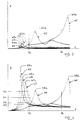
- FIG. 3 is a graph representing the rotating force F exerted by the rotor on the bearing, as a function of the speed V of rotation of the rotor and of different types of bearing support.
- the rotating force F on the ordinate is expressed in deca-Newton (DaN) and the rotational speed V on the abscissa is expressed in revolutions per minute (rpm).
- FIG. 4 is a graph representing the consumption of the clearance of the rotor relative to the stator as a function of the speed of rotation V of said rotor and of the bearing supports already invoked in FIG. 4.
- the consumption of clearance D is on the ordinate, and the speed of rotation V on the abscissa is expressed in revolutions per minute (rpm) with the same scale as in FIG. 3.
- the turbine engine is of the so-called "double flow" type usually used on large subsonic transport aircraft.
- turboshaft engines are well known to those skilled in the art, and in order not to unnecessarily burden this description, only the components of this turbine engine necessary for a good understanding of the invention will be described.
- the rotor 1 comprises in its central part a shaft 2 rotating around the geometric axis of rotation 3, and in its peripheral part in particular a fan stage 4 integral with the shaft 2 , said fan stage 4 extending towards the front of the turbine engine by the air inlet cone 5.
- the stage of fan 4 comprises a rim 6 integral with the shaft 2 at its front part, as well as a plurality of vanes 7 known as of fan arranged radially at the periphery of the rim 6.
- the vertices 8 of the vanes 7 arrive in the vicinity of the inner wall 9 of a casing 10 surrounding the fan stage 4.
- the part 9a of the inner wall 9 located opposite the tops 8 of the blades 7 is lined with an abradable coating 11 whose inner wall 12 is planed by the vertices of the vanes 8 during the first rotations of the rotor 1, this wall 12 however remaining approximately in the extension of the interior wall 9 of the casing 10.
- the reduced clearance thus formed will be referenced between the tops 8 of the vanes 7 and the interior wall 12 of the abradable 11.
- the play between the vertices 8 of the vanes 7 and the inner wall 9a of the casing 10 will also be referenced E, the play E being during the normal operation of the turbine engine obscured by the abradable 11.
- the shaft 2 and consequently the rotor 1 are guided in rotation along the geometric axis 3 and positioned in translation by a ball bearing 15 secured to the structure 16 of the turbine engine by means of a bearing support 17.
- This bearing 15 is arranged just behind the fan stage 4.
- Shaft 2 is also guided at the rear of the turbine engine by a roller bearing 18 secured to the structure 16 of the turbine engine by means of a other bearing support 19.
- the bearing support 17 has a general shape of revolution around the geometric axis 3.
- This bearing support 17 comprises a first flexible element 20 composed of a flexible frustoconical wall 21 whose large base 21a is extended radially outwards by a flange 22 fixed to the structure 16 of the turbine engine by a plurality of bolts 23.
- the small base 21b of the flexible wall 21 is extended axially by a member 24 enclosing the bearing 15, by its outer ring and radially outwards by a thin and flexible flange 25.
- the flanges 22 and 25 in this example each have the shape of a flat washer of geometric axis 3, therefore arranged in planes perpendicular to the axis 3, said flanges 22 and 25 each being integral by their inner circumference respectively to the large base 21a and the small base 21b of the frustoconical wall 21.
- the bearing support 17 also comprises a second flexible element 26 composed of a flexible frustoconical wall 27 whose large base 27a is extended radially outwards by a flange 28 fixed to the structure 16 by the same bolts 23, the flange 28 pressing on the flange 22.
- the small base 27b of the flexible wall 27 is extended radially inwards by a second flange 29 which arrives against the flange 25 with reduced play.
- the flanges 28 and 29 in this example each have the shape of a flat washer of geometric axis 3, therefore arranged in planes perpendicular to the axis 3, said flange 28 being integral by its inner circumference with the large base 27a of the wall 27, while the flange 29 is integral by its circumference outside the small base 27b of the wall 27.
- the flanges 25 and 29 are made integral by frangible connecting elements 30, that is to say capable of breaking under the effect of a predetermined radial force F applied to the bearing 15.
- the frangible elements 30 can be for example bolts arranged parallel to the geometric axis 3, the section of which is weakened and calculated as a function of the force F which must cause it to shear.
- the operation of the bearing support 17 is as follows. In normal operation, the frangible connecting elements 30 are not broken and link the flanges 25 and 29 against each other, so that the bearing 15 is held simultaneously by the flexible walls 21 and 27 whose stiffnesses are added together and combine with the stiffness of the structure 16 of the turbine engine. This stiffness is high and just makes it possible to absorb the force F resulting from the low manufacturing unbalance so that the space e between the tops 8 of the blades 7 and the inner wall 12 of the abradable 11 is minimal, which reduces air leakage at best.
- the frangible connecting elements 30 break so that the flexible element 26 can no longer participate in maintaining the bearing 15, this remaining function however provided by the flexible element 20 alone.
- the bearing 15 is therefore held radially with a reduced stiffness which is that of the flexible element 20 combined with that of the structure 16 of the turbine engine.
- the amplitude D of the radial displacement of the shaft 2 increases, and the flange 25 moves relative to the flange 29 along a plane perpendicular to the geometric axis 3.
- the diameters of the large bases 21a and 27a can be close.
- the small base 27b will be given a diameter much greater than that of the small base 21b, and the connecting elements 30 will be brought closer to one or the other of the bases 21b or 27b.
- This wider flange 25 or 29 is more flexible axially, that is to say parallel to the geometric axis 3, which reduces the axial stresses imposed on the frangible connecting elements 30.
- the flange 25 will be located at the front of the flange 29.
- the frangible connections 30 have broken, the fan stage 4 continues to provide a significant thrust and tends to pull towards the front of the turbine engine the shaft 2 and the bearing 15, the flange 25 will move slightly forward due to the residual flexibility of the wall 21 in an axial direction.
- the flange 25 is not then in contact with the flange 29 will not rub against it when the rotor will move in a plane perpendicular to the geometric axis 3 under the effect of accidental unbalance.
- the radial displacement D under the effect of the accidental unbalance of the bearing 15 is accompanied by a substantially equivalent displacement of the trajectory of the apices 8 of the blades 7.
- the vertices 8 of the vanes 7 come planing the abradable 11 to a depth equal to the radial displacement D.
- a turbine engine rotor has several stages of blades 31 grouped into functional assemblies such as the low pressure compressor 32 rotating inside a casing 33, said compressor 32 being located at the rear of the fan stage 4, therefore closer to the rear bearing 18.
- the radial displacement of the fan stage 4 having an impact on the radial displacement of each of the other stages 31, the skilled person will likewise have sufficient clearance between the tops of the blades of these stages 31 and the inner wall of the casing 33 which surrounds them, this play being in the same way obscured by an abradable.
- the line segment 35 represents the radial displacement D of the bearing 15 as a function of the rotating force F during the normal operation of the turbine engine. Under the effect of the elastic deformation of the bearing support, this displacement is linear and remains at very low values, just sufficient to absorb the manufacturing unbalance of the rotor.
- the rotating force F reaches a predetermined threshold Fo corresponding to the minimum unbalance from which we want to change the operation of the bearing support 17 and the turbine engine, the frangible elements break, the bearing becomes more flexible and the displacement D as a function of F is represented by the half-line 36 whose slope D / F is much greater than that of the line segment 35.
- the values on the abscissa represent the rotational speeds of the rotor 1.
- the ordinate values represent the rotating force F in daN (decanewton) that the rotor 1 exerts on the structure 16 via the bearing 15 and the bearing support 17.
- the set of curves is given for an unbalance of 3 kg.m corresponding approximately to the rupture of the upper third of a fan blade.
- the curve 10 represents the rotating force F in the case of a conventional bearing support 17 with a reduced clearance E between the vertices 8 of the blades 7 and the inner wall 9a of the casing 10.
- the bearing support 17 and the structure 16 are elastically deformed, and the apices 8 of the blades 7 plan the abradable 11 and come into contact with the wall 9a.
- the casing 10 then provides additional guidance of the fan stage 4 in cooperation with the bearing 15.
- the radial stiffness of the guide is in these conditions increased and corresponds to the stiffness of the casing 10 increased by that of the bearing support 17 combined with that of the structure 16, which has the effect of displacing the proper mode 40a of the rotor 1 beyond the maximum speed V2.
- the curve 41 represents this same effort rotating with the same bearing support 17 and a clearance E sufficient for the tops 8 of the blades 7 not to rub against the inner wall 9a of the casing 10.
- the proper mode 41a is in this example located in the lower first third of flight range V1-V2.
- the rotating force F remains greater than 25.10 3 DaN in the flight envelope and reaches 100.10 3 DaN with the proper mode 41a which is located this time in the lower third of the flight envelope.
- the simple enlargement of the set E cannot therefore provide a solution to the problem posed.
- the curves 42, 43 and 44 represent for three different flexibility levels the rotating force F with a bearing support 17 according to the invention, the frangible connections 30 being broken, the clearance E being assumed to be large enough for the vertices 8 vanes 7 do not rub against the internal wall 9a of the casing 10.
- the displacement D is significant throughout the flight domain V1-V2 and passes through a maximum in the lower third of this flight domain.
- the game E a value at least equal to the displacement D given by the curves 47, 48, 49 at the speed V1, namely the game consumption D1, D2 and D3 respectively.
- the turbine engine rotating at speeds greater than V1
- the vertices 8 of the blades 7 will not touch the wall 9a of the casing 10, in accordance with the main effect sought.
- the curves 41 or 42 of the graphs in FIG. 3 show that the rotating force F and the radial displacement D decrease when the speed of rotation V increases.
- the pilot can still mount or maintain the turboshaft engine at full throttle V2 to pass over obstacles that appear before it.
- Another advantage of the invention is that the rotating force F and the clearance consumption D can be reduced to very low levels while maintaining the axial positioning of the rotor by means of a thrust bearing; for example with a ball, this positioning being done without dissipation of heat by friction, unlike the devices disclosed by the patents FR 2,463,853 AND US 4,527,910 mentioned above.
- the invention can therefore be used without additional cooling means on large turboshaft engines.
- the bearing support 17 used has, at least in its preferred embodiment, a general shape, a size and modes of connection with the bearing 15 and the structure 16 of the turbine engine neighbors of bearings of known types and usually used on turboshaft engines. Consequently, the invention is applicable without calling into question the usual structures of turbine engines.
- Another advantage finally is that the risk of interaction between the casing and the rotor is reduced since the clearance E is increased.
- the present invention cannot be limited to the embodiment which has just been given. Although its most important application is the prevention of a fan blade failure, it can also be applied to other causes of rotor unbalance, in particular a blade failure on a compressor or turbine stage , by adapting sets E and bearing supports, for example 19, in accordance with the invention.
- turboshaft engines and in particular the larger ones may include an additional bearing holding the shaft 2 and arranged further behind the bearing 15 towards the bearing 18, the shaft 2 being relaxed.
- additional bearing support resulting from such an arrangement will advantageously be configured in accordance with the invention.
- a bearing support can also comprise N> 2 elastic elements, N-1 of these elements each comprising frangible connections whose resistance is increasing, in order to guard against damage going up.
Landscapes
- Engineering & Computer Science (AREA)
- General Engineering & Computer Science (AREA)
- Mechanical Engineering (AREA)
- Structures Of Non-Positive Displacement Pumps (AREA)
- Supercharger (AREA)
Applications Claiming Priority (2)
| Application Number | Priority Date | Filing Date | Title |
|---|---|---|---|
| FR9607328A FR2749883B1 (fr) | 1996-06-13 | 1996-06-13 | Procede et support de palier permettant de maintenir en fonctionnement un turbomoteur pour aeronef apres apparition d'un balourd accidentel sur un rotor |
| FR9607328 | 1996-06-13 |
Publications (2)
| Publication Number | Publication Date |
|---|---|
| EP0814236A1 true EP0814236A1 (de) | 1997-12-29 |
| EP0814236B1 EP0814236B1 (de) | 2002-03-13 |
Family
ID=9493009
Family Applications (1)
| Application Number | Title | Priority Date | Filing Date |
|---|---|---|---|
| EP97401324A Expired - Lifetime EP0814236B1 (de) | 1996-06-13 | 1997-06-12 | Lagerträger, der es erlaubt ein Turbotriebwerk auch nach dem Auftreten einer Unwucht in Betrieb zu halten |
Country Status (6)
| Country | Link |
|---|---|
| US (1) | US5974782A (de) |
| EP (1) | EP0814236B1 (de) |
| JP (1) | JP3393037B2 (de) |
| CA (1) | CA2206154C (de) |
| DE (1) | DE69710949T2 (de) |
| FR (1) | FR2749883B1 (de) |
Cited By (8)
| Publication number | Priority date | Publication date | Assignee | Title |
|---|---|---|---|---|
| EP0874137A2 (de) * | 1997-04-24 | 1998-10-28 | United Technologies Corporation | Rotorlagerung für ein Turbotriebwerk |
| US6428269B1 (en) | 2001-04-18 | 2002-08-06 | United Technologies Corporation | Turbine engine bearing support |
| EP1008726A3 (de) * | 1998-12-09 | 2004-01-02 | General Electric Company | System zum Loskoppeln eines Bläsers |
| EP1553324A1 (de) * | 2004-01-12 | 2005-07-13 | Snecma Moteurs | Lagerträger mit doppelter Steifigkeit |
| US7448808B2 (en) | 2003-06-20 | 2008-11-11 | Snecma | Arrangement of bearing supports for the rotating shaft of an aircraft engine and an aircraft engine fitted with such an arrangement |
| GB2454327A (en) * | 2007-10-30 | 2009-05-06 | Honeywell Int Inc | Sequential stiffness support for bearing assemblies |
| US8845277B2 (en) | 2010-05-24 | 2014-09-30 | United Technologies Corporation | Geared turbofan engine with integral gear and bearing supports |
| RU2578935C1 (ru) * | 2014-10-30 | 2016-03-27 | Открытое акционерное общество "Уфимское моторостроительное производственное объединение" ОАО "УМПО" | Упругая опора с регулируемой жесткостью для стендовых динамических испытаний роторов турбомашин |
Families Citing this family (39)
| Publication number | Priority date | Publication date | Assignee | Title |
|---|---|---|---|---|
| GB2326679B (en) * | 1997-06-25 | 2000-07-26 | Rolls Royce Plc | Ducted fan gas turbine engine |
| US6364603B1 (en) * | 1999-11-01 | 2002-04-02 | Robert P. Czachor | Fan case for turbofan engine having a fan decoupler |
| US6439772B1 (en) | 2000-12-01 | 2002-08-27 | General Electric Company | Method and apparatus for supporting rotor assembly bearings |
| US6443698B1 (en) | 2001-01-26 | 2002-09-03 | General Electric Company | Method and apparatus for centering rotor assembly damper bearings |
| US6413046B1 (en) | 2001-01-26 | 2002-07-02 | General Electric Company | Method and apparatus for centering rotor assembly damper bearings |
| US6783319B2 (en) | 2001-09-07 | 2004-08-31 | General Electric Co. | Method and apparatus for supporting rotor assemblies during unbalances |
| FR2832191B1 (fr) | 2001-11-14 | 2004-10-08 | Snecma Moteurs | Aube de soufflante a sommet fragilise |
| EP1314854A1 (de) * | 2001-11-23 | 2003-05-28 | Techspace Aero S.A. | Entkopplungseinrichtung für einen Luftfahrzeugsmotor |
| US7097412B2 (en) * | 2003-02-14 | 2006-08-29 | United Technologies Corporation | Turbine engine bearing support |
| US7097413B2 (en) * | 2004-05-12 | 2006-08-29 | United Technologies Corporation | Bearing support |
| FR2871517B1 (fr) * | 2004-06-11 | 2006-09-01 | Snecma Moteurs Sa | Turbomachine avec moyens de retenue axiale du rotor |
| US7384199B2 (en) * | 2004-08-27 | 2008-06-10 | General Electric Company | Apparatus for centering rotor assembly bearings |
| FR2888621B1 (fr) * | 2005-07-15 | 2007-10-05 | Snecma | Dispositif de retention d'un support de palier dans une turbomachine comportant un dispositif de decouplage |
| US7603844B2 (en) * | 2005-10-19 | 2009-10-20 | General Electric Company | Gas turbine engine assembly and methods of assembling same |
| US7841165B2 (en) * | 2006-10-31 | 2010-11-30 | General Electric Company | Gas turbine engine assembly and methods of assembling same |
| US7742881B2 (en) | 2007-08-02 | 2010-06-22 | General Electric Company | System and method for detection of rotor eccentricity baseline shift |
| US8262353B2 (en) * | 2007-11-30 | 2012-09-11 | General Electric Company | Decoupler system for rotor assemblies |
| FR2926603B1 (fr) * | 2008-01-23 | 2010-03-26 | Snecma | Guidage d'un arbre dans une turbomachine |
| US8702377B2 (en) | 2010-06-23 | 2014-04-22 | Honeywell International Inc. | Gas turbine engine rotor tip clearance and shaft dynamics system and method |
| GB201015437D0 (en) * | 2010-09-16 | 2010-10-27 | Rolls Royce Plc | Gas turbine engine bearing arrangement |
| US20120275921A1 (en) * | 2011-04-28 | 2012-11-01 | General Electric Company | Turbine engine and load reduction device thereof |
| US9080461B2 (en) | 2012-02-02 | 2015-07-14 | Pratt & Whitney Canada Corp. | Fan and boost joint |
| EP2886804B1 (de) * | 2013-12-20 | 2017-08-16 | Safran Aero Boosters SA | Dichtungsanordnung für einen Verdicther eines Turbotriebwerks |
| US9777596B2 (en) | 2013-12-23 | 2017-10-03 | Pratt & Whitney Canada Corp. | Double frangible bearing support |
| US9777592B2 (en) | 2013-12-23 | 2017-10-03 | Pratt & Whitney Canada Corp. | Post FBO windmilling bumper |
| RU2541623C1 (ru) * | 2014-01-29 | 2015-02-20 | Открытое акционерное общество "Уфимское моторостроительное производственное объединение" ОАО "УМПО" | Упругая опора ротора турбомашины |
| US9909451B2 (en) | 2015-07-09 | 2018-03-06 | General Electric Company | Bearing assembly for supporting a rotor shaft of a gas turbine engine |
| CN107237655B (zh) * | 2016-03-28 | 2019-03-15 | 中国航发商用航空发动机有限责任公司 | 航空发动机及其风扇叶片飞脱载荷下熔断方法 |
| CN107780984B (zh) * | 2016-08-31 | 2019-09-20 | 中国航发商用航空发动机有限责任公司 | 可失效转子支承结构及航空发动机 |
| US10274017B2 (en) * | 2016-10-21 | 2019-04-30 | General Electric Company | Method and system for elastic bearing support |
| CN108071429B (zh) * | 2016-11-17 | 2019-11-12 | 中国航发商用航空发动机有限责任公司 | 可失效转子支承结构及航空发动机 |
| US10808573B1 (en) | 2019-03-29 | 2020-10-20 | Pratt & Whitney Canada Corp. | Bearing housing with flexible joint |
| US11105223B2 (en) | 2019-08-08 | 2021-08-31 | General Electric Company | Shape memory alloy reinforced casing |
| US11420755B2 (en) | 2019-08-08 | 2022-08-23 | General Electric Company | Shape memory alloy isolator for a gas turbine engine |
| US11274557B2 (en) | 2019-11-27 | 2022-03-15 | General Electric Company | Damper assemblies for rotating drum rotors of gas turbine engines |
| US11280219B2 (en) | 2019-11-27 | 2022-03-22 | General Electric Company | Rotor support structures for rotating drum rotors of gas turbine engines |
| US11828235B2 (en) | 2020-12-08 | 2023-11-28 | General Electric Company | Gearbox for a gas turbine engine utilizing shape memory alloy dampers |
| US11492926B2 (en) | 2020-12-17 | 2022-11-08 | Pratt & Whitney Canada Corp. | Bearing housing with slip joint |
| FR3129174A1 (fr) * | 2021-11-15 | 2023-05-19 | Safran Aircraft Engines | Module de turbomachine comprenant un dispositif d’amortissement et turbomachine correspondante |
Citations (7)
| Publication number | Priority date | Publication date | Assignee | Title |
|---|---|---|---|---|
| FR2115316A1 (de) * | 1970-11-21 | 1972-07-07 | United Kingdom Government | |
| FR2181366A5 (de) * | 1972-04-18 | 1973-11-30 | Rolls Royce | |
| GB1418907A (en) * | 1972-06-23 | 1975-12-24 | Rolls Royce | Bearing assemblies |
| FR2452034A1 (fr) * | 1979-03-17 | 1980-10-17 | Rolls Royce | Perfectionnement au montage d'ensembles rotors |
| FR2453273A1 (fr) * | 1979-04-07 | 1980-10-31 | Rolls Royce | Ensemble de rotor, notamment pour une turbomachine |
| GB2281105A (en) * | 1993-08-21 | 1995-02-22 | Westland Helicopters | Bearing assembly |
| US5433584A (en) * | 1994-05-05 | 1995-07-18 | Pratt & Whitney Canada, Inc. | Bearing support housing |
Family Cites Families (5)
| Publication number | Priority date | Publication date | Assignee | Title |
|---|---|---|---|---|
| US3529905A (en) * | 1966-12-12 | 1970-09-22 | Gen Motors Corp | Cellular metal and seal |
| US3836156A (en) * | 1971-07-19 | 1974-09-17 | United Aircraft Canada | Ablative seal |
| US4289360A (en) * | 1979-08-23 | 1981-09-15 | General Electric Company | Bearing damper system |
| FR2504980B1 (fr) * | 1981-04-29 | 1985-06-14 | Snecma | Montage de palier, en particulier pour turbomachines |
| US4527910A (en) * | 1984-04-05 | 1985-07-09 | The United States Of America As Represented By The Administrator Of The National Aeronautics And Space Administration | Dual clearance squeeze film damper |
-
1996
- 1996-06-13 FR FR9607328A patent/FR2749883B1/fr not_active Expired - Fee Related
-
1997
- 1997-05-13 CA CA002206154A patent/CA2206154C/fr not_active Expired - Fee Related
- 1997-06-12 US US08/873,452 patent/US5974782A/en not_active Expired - Lifetime
- 1997-06-12 EP EP97401324A patent/EP0814236B1/de not_active Expired - Lifetime
- 1997-06-12 DE DE69710949T patent/DE69710949T2/de not_active Expired - Lifetime
- 1997-06-13 JP JP15656897A patent/JP3393037B2/ja not_active Expired - Lifetime
Patent Citations (7)
| Publication number | Priority date | Publication date | Assignee | Title |
|---|---|---|---|---|
| FR2115316A1 (de) * | 1970-11-21 | 1972-07-07 | United Kingdom Government | |
| FR2181366A5 (de) * | 1972-04-18 | 1973-11-30 | Rolls Royce | |
| GB1418907A (en) * | 1972-06-23 | 1975-12-24 | Rolls Royce | Bearing assemblies |
| FR2452034A1 (fr) * | 1979-03-17 | 1980-10-17 | Rolls Royce | Perfectionnement au montage d'ensembles rotors |
| FR2453273A1 (fr) * | 1979-04-07 | 1980-10-31 | Rolls Royce | Ensemble de rotor, notamment pour une turbomachine |
| GB2281105A (en) * | 1993-08-21 | 1995-02-22 | Westland Helicopters | Bearing assembly |
| US5433584A (en) * | 1994-05-05 | 1995-07-18 | Pratt & Whitney Canada, Inc. | Bearing support housing |
Cited By (14)
| Publication number | Priority date | Publication date | Assignee | Title |
|---|---|---|---|---|
| EP0874137A2 (de) * | 1997-04-24 | 1998-10-28 | United Technologies Corporation | Rotorlagerung für ein Turbotriebwerk |
| EP0874137A3 (de) * | 1997-04-24 | 1999-12-29 | United Technologies Corporation | Rotorlagerung für ein Turbotriebwerk |
| EP1008726A3 (de) * | 1998-12-09 | 2004-01-02 | General Electric Company | System zum Loskoppeln eines Bläsers |
| US6428269B1 (en) | 2001-04-18 | 2002-08-06 | United Technologies Corporation | Turbine engine bearing support |
| US7448808B2 (en) | 2003-06-20 | 2008-11-11 | Snecma | Arrangement of bearing supports for the rotating shaft of an aircraft engine and an aircraft engine fitted with such an arrangement |
| FR2864995A1 (fr) * | 2004-01-12 | 2005-07-15 | Snecma Moteurs | Support de palier a double raideur |
| EP1553324A1 (de) * | 2004-01-12 | 2005-07-13 | Snecma Moteurs | Lagerträger mit doppelter Steifigkeit |
| US7524112B2 (en) | 2004-01-12 | 2009-04-28 | Snecma | Bearing support with double stiffener |
| GB2454327A (en) * | 2007-10-30 | 2009-05-06 | Honeywell Int Inc | Sequential stiffness support for bearing assemblies |
| GB2454327B (en) * | 2007-10-30 | 2009-11-04 | Honeywell Int Inc | Sequential stiffness support for bearing assemblies and method of fabrication |
| US8267650B2 (en) | 2007-10-30 | 2012-09-18 | Honeywell International Inc. | Sequential stiffness support for bearing assemblies and method of fabrication |
| US8845277B2 (en) | 2010-05-24 | 2014-09-30 | United Technologies Corporation | Geared turbofan engine with integral gear and bearing supports |
| US9638062B2 (en) | 2010-05-24 | 2017-05-02 | United Technologies Corporation | Geared turbofan engine with integral gear and bearing supports |
| RU2578935C1 (ru) * | 2014-10-30 | 2016-03-27 | Открытое акционерное общество "Уфимское моторостроительное производственное объединение" ОАО "УМПО" | Упругая опора с регулируемой жесткостью для стендовых динамических испытаний роторов турбомашин |
Also Published As
| Publication number | Publication date |
|---|---|
| JP3393037B2 (ja) | 2003-04-07 |
| US5974782A (en) | 1999-11-02 |
| FR2749883A1 (fr) | 1997-12-19 |
| DE69710949T2 (de) | 2002-10-17 |
| CA2206154C (fr) | 2004-12-14 |
| DE69710949D1 (de) | 2002-04-18 |
| EP0814236B1 (de) | 2002-03-13 |
| JPH1061494A (ja) | 1998-03-03 |
| FR2749883B1 (fr) | 1998-07-31 |
| CA2206154A1 (fr) | 1997-12-13 |
Similar Documents
| Publication | Publication Date | Title |
|---|---|---|
| EP0814236B1 (de) | Lagerträger, der es erlaubt ein Turbotriebwerk auch nach dem Auftreten einer Unwucht in Betrieb zu halten | |
| EP2088290B1 (de) | Versteifender Gehäuseabreibbelag in einem Turbotriebwerk | |
| CA2521265C (fr) | Dispositif de limitation de survitesse de turbine dans une turbomachine | |
| EP2083150B1 (de) | Führung einer Welle in einem Turbotriebwerk | |
| EP2622181B1 (de) | Gasturbinenmotor mit vorrichtung zur axialen fixierung eines lüfters des motors | |
| FR2826052A1 (fr) | Dispositif de secours au rallumage d'un turboreacteur en autorotation | |
| FR2645902A1 (fr) | Masselotte d'equilibrage sans boulons pour des rotors de turbine | |
| EP3430241A1 (de) | Turbolüfter | |
| WO2009144409A1 (fr) | Bride annulaire de fixation d'un element de rotor ou de stator | |
| CA2478788A1 (fr) | Dispositif abradable sur carter de soufflante d'un moteur de turbine a gaz | |
| EP1593816A1 (de) | Turbomaschine mit einem Blockiersystem für die Haupttriebwerkswelle mit Lager-Sollbruchstelle | |
| FR3030614A1 (fr) | Ensemble de turbine haute pression de turbomachine | |
| EP3775500B1 (de) | Turbinenwelle einer turbomaschine und verfahren zum schutz vor überhöhter drehzahl dieser welle | |
| WO2015022474A1 (fr) | Rotor pour helice de turbomachine avec dispositif de mise en drapeau des pales de l'helice | |
| EP3589832B1 (de) | Triebwerkseinlaufanordnung mit mechanischem entkoppler | |
| FR2951502A1 (fr) | Architecture de turbomachine ameliorant l'admission d'air | |
| EP4062034B1 (de) | Turbofanlaufschaufel, turbofan und damit versehene turbomaschine | |
| EP3935265B1 (de) | Rotor einer flugzeugturbomaschine mit dämpfungsvorrichtung | |
| WO2012069773A1 (fr) | Dispositif de desaccouplement d'un support de palier | |
| FR3108659A1 (fr) | Rotor de turbine comprenant un dispositif de régulation du débit de fluide de refroidissement et turbomachine comprenant un tel rotor | |
| FR2875850A1 (fr) | Carter de rotor de turbomachine pour la retention de corps projetes par le rotor en rotation et procede d'obtention | |
| FR2877994A1 (fr) | Support de palier, et moteur d'aeronef equipe d'un tel support de palier. | |
| FR3129174A1 (fr) | Module de turbomachine comprenant un dispositif d’amortissement et turbomachine correspondante | |
| FR3134136A1 (fr) | Turbomachine d’aeronef comprenant un support de roulement a conception amelioree | |
| FR3121169A1 (fr) | Cone d’entree pour une turbomachine d’aeronef |
Legal Events
| Date | Code | Title | Description |
|---|---|---|---|
| PUAI | Public reference made under article 153(3) epc to a published international application that has entered the european phase |
Free format text: ORIGINAL CODE: 0009012 |
|
| 17P | Request for examination filed |
Effective date: 19970626 |
|
| AK | Designated contracting states |
Kind code of ref document: A1 Designated state(s): DE FR GB |
|
| AKX | Designation fees paid |
Free format text: DE FR GB |
|
| RBV | Designated contracting states (corrected) |
Designated state(s): DE FR GB |
|
| 17Q | First examination report despatched |
Effective date: 20001016 |
|
| GRAG | Despatch of communication of intention to grant |
Free format text: ORIGINAL CODE: EPIDOS AGRA |
|
| GRAG | Despatch of communication of intention to grant |
Free format text: ORIGINAL CODE: EPIDOS AGRA |
|
| GRAH | Despatch of communication of intention to grant a patent |
Free format text: ORIGINAL CODE: EPIDOS IGRA |
|
| GRAH | Despatch of communication of intention to grant a patent |
Free format text: ORIGINAL CODE: EPIDOS IGRA |
|
| RAP1 | Party data changed (applicant data changed or rights of an application transferred) |
Owner name: SNECMA MOTEURS |
|
| REG | Reference to a national code |
Ref country code: GB Ref legal event code: IF02 |
|
| GRAA | (expected) grant |
Free format text: ORIGINAL CODE: 0009210 |
|
| AK | Designated contracting states |
Kind code of ref document: B1 Designated state(s): DE FR GB |
|
| REF | Corresponds to: |
Ref document number: 69710949 Country of ref document: DE Date of ref document: 20020418 |
|
| GBT | Gb: translation of ep patent filed (gb section 77(6)(a)/1977) |
Effective date: 20020520 |
|
| PLBE | No opposition filed within time limit |
Free format text: ORIGINAL CODE: 0009261 |
|
| STAA | Information on the status of an ep patent application or granted ep patent |
Free format text: STATUS: NO OPPOSITION FILED WITHIN TIME LIMIT |
|
| 26N | No opposition filed |
Effective date: 20021216 |
|
| REG | Reference to a national code |
Ref country code: FR Ref legal event code: CD |
|
| PGFP | Annual fee paid to national office [announced via postgrant information from national office to epo] |
Ref country code: DE Payment date: 20150521 Year of fee payment: 19 Ref country code: GB Payment date: 20150527 Year of fee payment: 19 |
|
| REG | Reference to a national code |
Ref country code: FR Ref legal event code: PLFP Year of fee payment: 20 |
|
| PGFP | Annual fee paid to national office [announced via postgrant information from national office to epo] |
Ref country code: FR Payment date: 20160616 Year of fee payment: 20 |
|
| REG | Reference to a national code |
Ref country code: DE Ref legal event code: R119 Ref document number: 69710949 Country of ref document: DE |
|
| GBPC | Gb: european patent ceased through non-payment of renewal fee |
Effective date: 20160612 |
|
| PG25 | Lapsed in a contracting state [announced via postgrant information from national office to epo] |
Ref country code: DE Free format text: LAPSE BECAUSE OF NON-PAYMENT OF DUE FEES Effective date: 20170103 |
|
| PG25 | Lapsed in a contracting state [announced via postgrant information from national office to epo] |
Ref country code: GB Free format text: LAPSE BECAUSE OF NON-PAYMENT OF DUE FEES Effective date: 20160612 |
|
| REG | Reference to a national code |
Ref country code: FR Ref legal event code: CD Owner name: SAFRAN AIRCRAFT ENGINES Effective date: 20170717 |