EP0814018A2 - Gewellter Holmsteg mit verminderter Amplitude - Google Patents
Gewellter Holmsteg mit verminderter Amplitude Download PDFInfo
- Publication number
- EP0814018A2 EP0814018A2 EP97201663A EP97201663A EP0814018A2 EP 0814018 A2 EP0814018 A2 EP 0814018A2 EP 97201663 A EP97201663 A EP 97201663A EP 97201663 A EP97201663 A EP 97201663A EP 0814018 A2 EP0814018 A2 EP 0814018A2
- Authority
- EP
- European Patent Office
- Prior art keywords
- spar
- corrugated web
- web
- corrugated
- fasteners
- Prior art date
- Legal status (The legal status is an assumption and is not a legal conclusion. Google has not performed a legal analysis and makes no representation as to the accuracy of the status listed.)
- Withdrawn
Links
Images


Classifications
-
- B—PERFORMING OPERATIONS; TRANSPORTING
- B64—AIRCRAFT; AVIATION; COSMONAUTICS
- B64C—AEROPLANES; HELICOPTERS
- B64C9/00—Adjustable control surfaces or members, e.g. rudders
- B64C9/14—Adjustable control surfaces or members, e.g. rudders forming slots
- B64C9/16—Adjustable control surfaces or members, e.g. rudders forming slots at the rear of the wing
- B64C9/18—Adjustable control surfaces or members, e.g. rudders forming slots at the rear of the wing by single flaps
-
- E—FIXED CONSTRUCTIONS
- E04—BUILDING
- E04C—STRUCTURAL ELEMENTS; BUILDING MATERIALS
- E04C3/00—Structural elongated elements designed for load-supporting
- E04C3/02—Joists; Girders, trusses, or trusslike structures, e.g. prefabricated; Lintels; Transoms; Braces
- E04C3/28—Joists; Girders, trusses, or trusslike structures, e.g. prefabricated; Lintels; Transoms; Braces of materials not covered by groups E04C3/04 - E04C3/20
Definitions
- This invention relates to aircraft, and more particularly relates to reinforcing structures within the wings, fuselage, and empennage of an airplane.
- the wings for an airplane undergo a large amount of stress during flight of the airplane.
- a typical wing structure includes outer surfaces, or “skins” attached to an internal frame.
- the frame of the wing includes a number of reinforcements, called “spars,” that lie vertically within the wing extending from the body of the plane to the outer tip of the wing.
- the skin is attached to the spars and the spars provide structural integrity for the wings.
- the wings of an airplane must be designed to withstand the forces that occur during operation. During flight maneuvers, enormous forces are placed on the spars and other frame members of the wing. The forces are a result of aerodynamic and inertia loads. A rolling maneuver results in centripetal acceleration which pressurizes the fuel in the wing. Fuel pressure forces applied to the skins are counteracted by the spars and frames. To prevent release of the skins from the spars, the spars and the attachment of the spars to the skins must have adequate "pull-off strength". The frames of the wing must also be capable of withstanding shear loads that occur during flight.. The frames must have sufficient stiffness to support the general stability of the wing skins, and avoid flutter.
- a frame must not only have structural strength which allows the wing to withstand stresses during flight, but also be lightweight so as to maximize the efficiency of the airplane.
- wings are usually designed to hold the fuel for the airplane. Any non-accessible voids created in the interior of the wing by the frame are volume that cannot be used to store fuel. Frame volume also reduces fuel storage.
- frames be made of members that permit fuel to flow within a wing and do not require a large volume. Minimizing the volume becomes especially important when designing new supersonic fighters that have low-profile wings.
- Corrugated spars have the appearance of an I-beam construction, with the web or central portion of the beam having a corrugated shape. The corrugations extend perpendicular to and between the top and bottom flanges of the I-beams.
- Corrugated spars are usually made of a laminar composite, such as a woven graphite fiber composite. The matrix material is typically a resin such as epoxy.
- Prior art corrugated web spars utilized corrugation designs whose amplitude and wavelength were determined by fastener location requirements.
- An example of a prior art corrugated web spar is shown in FIGURE 6.
- Fasteners on the prior art planes are arranged linearly along the length of the bottom and top flanges of the corrugated web spars. The fasteners extend into the top and bottom flanges of the web spars and are located in the valleys defined by the corrugations. A large number of fasteners are required to provide adequate pull-off strength.
- Fastener spacing on prior art corrugated web spars is usually in the range of 5 to 7 times the fastener diameter. Because the fasteners were located in a single line extending down the center of the spar, the wavelength of the previous corrugated web designs is twice the fastener spacing, or 10 to 14 times the fastener diameter.
- the fasteners are attached one flange of the spar by a nut or collar, and the other flange by a nut plate.
- prior art web spars require a minimum corrugation amplitude.
- the short wavelength and the required minimum corrugation amplitude resulted in spars having a geometry that was difficult to manufacture.
- the present invention provides a reduced amplitude corrugated web spar. To resolve many of the above problems, the present invention reduces the amplitude of the corrugation, and offsets the fasteners from the spar center line, resulting in a reduced amplitude corrugated web spar. The resulting spar is easier to manufacture and still provides the structural integrity required by the wings of an airplane.
- the present invention provides a method of forming a corrugated web spar for use as a support structure in an airplane.
- the method includes the steps of determining the general stability required of the corrugated spar and forming the corrugated spar with corrugations having an amplitude that meets the determined general stability requirements. If fasteners are used, it is preferred that the fasteners are offset from the center line of the corrugated spar the minimum distance required so that the fasteners do not interfere with the web of the corrugated spar.
- the present invention further provides a corrugated web spar for use as a support structure in an airplane.
- the corrugated web spar includes a top flange, a bottom flange, and a corrugated web sheet extending between the top flange and the bottom flange, the corrugated web including corrugations having an amplitude which is substantially equivalent to the minimum amplitude required to meet the general stability design requirements of the corrugated spar.
- the corrugated web spar also includes fastener holes in the top and bottom flanges for attaching an airplane skin to the corrugated web spar, the fastener holes being offset on the top and bottom flanges from the center line of the corrugated sheet so that the fasteners do not interfere with the corrugated sheet.
- FIGURE 1 illustrates an airplane 20 incorporating the present invention.
- the airplane 20 includes a body (or fuselage) 22 and wings 24.
- the wings 24 each have skins 25 attached to an internal frame 26.
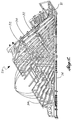
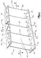
- the frame 26 is shown in detail in FIGURE 2.
- the frame 26 includes a plurality of corrugated web spars 30 extending from the body 22 of the airplane 20 out toward the tip 31 of the wing 24.
- a number of cross-braces 32 extend across the frame 26.
- end pieces 34 extend around the outer perimeter of the frame 26.
- the corrugated web spars 30 are preferably made from a woven graphite-fiber composite.
- the density and arrangement of the fibers in the structure, as well as their orientation and arrangement, can be chosen by a person of skill in the art to achieve desired structural features.
- a variety of matrix materials may be used, including both thermosets and thermoplastics.
- An example of a matrix material is epoxy.
- the corrugated web spar 30 includes a corrugated web 38 having a sinusoidal pattern of corrugations 39.
- the corrugated web 38 is integrally formed with a top flange 40 and a bottom flange 42.
- the top flange 40, the bottom flange 42, and the corrugated web 38 form an I-beam structure with the corrugated web 38 forming the central portion or web of the I-beam.
- the top flange 40 includes fastener holes 44 (FIGURE 3) bored therethrough.
- the bottom flange 42 includes fastener holes 46 (FIGURE 4) bored therethrough.
- flush head fasteners are used to secure the skins 25 to the spars 30.
- the flush head fasteners are countersunk in the wing skins 25 so a smooth aerodynamic surface is achieved.
- the flush head fasteners are retained by nuts or nut plates inside the wing.
- the fastener holes 44, 46 are adapted to receive the fasteners.
- the fasteners extend through the bottom skin 25 of the airplane wing and through the bottom fastener holes 46. Nuts or collars (not shown) are attached in a manner known in the art to the ends of the fasteners lying beside the corrugated web.
- nut plates are riveted or attached to the top flange 40 of the spars 30.
- the nut plates include a female threaded hole and are mounted in alignment with the fastener holes 44 in the top flange 40.
- additional fasteners are used to attach the top wing skin 25 to the spars 30.
- the additional fasteners extend through holes in the top skin of the wing 24, through fastener holes 44 and into the female threaded holes in the nut plates.
- the fasteners are tightened to securely fasten the skins 25 to the spars 30.
- the upper wing skin 25 could be fastened to the upper spar flange 40 using nuts first, and then the lower wing skin 25 could be fastened to nut plates in the lower spar flange 42 second.
- the corrugated web 38 includes fuel holes 50 (FIGURE 3) drilled through the flat 52 part of the web (FIGURE 4) near the bottom of the corrugations 39, and vent holes 56 drilled along the top of the flat parts 52. It is preferred that the flat parts 52 be wide enough to allow the fuel and vent holes 50, 56 to be located on the flat parts and not on the curved surfaces of the corrugations 39 of the corrugated web 38.
- the fuel holes 50 and vent holes 56 aid in the circulation of the fuel within the wings 24 to a fuel line (not shown, but well-known in the art).
- the fuel holes 50 are preferably 1/2 inch in diameter, and the vent holes 56 are preferably 1/4 inch in diameter.
- the corrugated web 38 includes thickened portions 58, 60 at its bottom and top, respectively, to account for weakening of the structure due to the addition of the holes 50, 56 located at the bottom and top portions of the corrugated web.
- FIGURE 6 is an elevational view of the bottom half of a prior art corrugated web spar 62.
- the prior art corrugated web spar 62 includes fastener holes 64, a corrugated web 65 having corrugations 66, a bottom flange 68, and a top flange (not shown).
- the fastener holes 64 in the prior art corrugated web spar 62 are arranged linearly down the center of the bottom flange 68. This arrangement requires that the corrugations 66 have a minimum corrugation amplitude in order for the fasteners not to interfere with the corrugations 66 of the corrugated web 65.
- the angles formed at the corrugations 66 are severe enough that a corrugated web spar 62 manufactured from a woven graphite fiber web composite is difficult to manufacture.
- the main variables affecting general stability of a corrugated web spar are web thickness (t), spar depth (b), and corrugation area moment of inertia (I y ).
- Corrugation area moment of inertia (I y ) is dependent upon the amplitude and wavelength (FIGURE 4) of the corrugations 39, and can be calculated by one of many computer programs that are well known in the art.
- the A and D values are from matrices which represent the extensional stiffness and flexural stiffness of a laminate. These values can be calculated, or are readily available to a person of skill in the art, for the laminate composite chosen for the corrugated web spars 30.
- the spar depth (b) is determined generally at the maximum depth of the majority of the wing. For a supersonic fighter, typically 80 percent of the wing is shallower than 9.0 inches. In determining the spar depth (b), the thickened portions 58, 60, are not used. In the example shown in the drawing, these thickened portions are approximately 1 inch long. Therefore, the spar depth (b) used for the general stability calculation for the spar 30 used in a supersonic fighter is 7 inches.
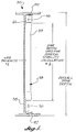
- Web thickness (t) is determined by the required shear flow of the spar 30. Shear flow is the load carried by the spar 30 divided by the overall spar depth (FIGURE 5). A typical design ultimate load (DUL) shear flow requirement would be less than 1,000 lbs./inch.
- DUL design ultimate load
- six prepreg laminas of the woven graphite fiber web were cured to form the corrugated web 38. These prepreg laminas are cured along with adequate laminas to form the top and bottom flanges 40, 42 and the thickened portions 58, 60.
- a person of skill in the art can choose the desired method of formation of the corrugated web spars 30, using methods which are appropriate to the graphite fiber web and matrix material chosen.
- spar fastener spacing is usually in the range of five to seven times the fastener diameters.
- An exemplary fastener spacing has been found to be 1.25 inches. This fastener spacing works for both .190 inches and .250 inches diameter fasteners. The most commonly used wing skin-to-spar fasteners have these diameters.
- the web corrugation wavelength is twice the fastener spacing, or 2.5 inches.
- the corrugation amplitude is calculated by using the general stability equation.
- the desired general stability may be a predetermined value, or may be determined as a relative value to the DUL. For example, if it is desired that a corrugated web spar 30 be designed such that shear or pristine strength failure would occur prior to a general stability failure, then the spar must be stable to points greater than the rated DUL shear flow. One way of assuring this relationship is to make the calculated general stability failure occur at a shear flow twice as high as the DUL shear flow.
- a corrugation amplitude could be chosen which is great enough to keep the spar stable to approximately 200 percent of its rated DUL shear flow.
- the amplitude of the corrugated web spar 30 having the dimensions described above is approximately .28 inches.
- a corrugated web spar 30 having the dimensions described above provides flats 52 with sufficient room for the fuel and vent holes 50, 56.
- the flats 52 are also of sufficient size to allow attachment of brackets and to accept repair fasteners as needed.
- the fasteners are offset the minimum required distance from the spar web so as not to interfere with the corrugations 39.
- the minimum required distance is that distance which accounts for manufacturing tolerances, and allows for a repair fastener (presumably of larger size than the standard fastener) to be installed in the spar without interfering with the web.
- the minimum required offset would be different for a .190 inch diameter fastener than a .250 inch diameter fastener.
- Fasteners are offset the minimum required distance to provide a spar with greater stiffness and "pull-off strength" and to minimize spar weight by minimizing flange widths 40 and 42.
- the skin could instead be attached by bonding, co-curing, or other methods which are well known in the art.
- corrugated web spar 30 of the present invention could be used in empennage for an airplane or in other parts of the airplane needing structural stiffness.
Applications Claiming Priority (2)
| Application Number | Priority Date | Filing Date | Title |
|---|---|---|---|
| US08/667,838 US5848765A (en) | 1996-06-20 | 1996-06-20 | Reduced amplitude corrugated web spar |
| US667838 | 1996-06-20 |
Publications (2)
| Publication Number | Publication Date |
|---|---|
| EP0814018A2 true EP0814018A2 (de) | 1997-12-29 |
| EP0814018A3 EP0814018A3 (de) | 1999-03-03 |
Family
ID=24679860
Family Applications (1)
| Application Number | Title | Priority Date | Filing Date |
|---|---|---|---|
| EP97201663A Withdrawn EP0814018A3 (de) | 1996-06-20 | 1997-06-09 | Gewellter Holmsteg mit verminderter Amplitude |
Country Status (3)
| Country | Link |
|---|---|
| US (1) | US5848765A (de) |
| EP (1) | EP0814018A3 (de) |
| CA (1) | CA2207403A1 (de) |
Cited By (1)
| Publication number | Priority date | Publication date | Assignee | Title |
|---|---|---|---|---|
| EP2708463A1 (de) * | 2012-09-14 | 2014-03-19 | Bell Helicopter Textron Inc. | Methode zur Optimierung und Anpassung der Struktureigenschaften von Rotorblättern, bestehend aus der Massschneidung von grosszellig-Faserverbundkernen, und damit ausgestattetem Rotorblatt |
Families Citing this family (30)
| Publication number | Priority date | Publication date | Assignee | Title |
|---|---|---|---|---|
| JP2000006893A (ja) * | 1998-06-23 | 2000-01-11 | Fuji Heavy Ind Ltd | 複合材翼構造 |
| US6889937B2 (en) * | 1999-11-18 | 2005-05-10 | Rocky Mountain Composites, Inc. | Single piece co-cure composite wing |
| US7681835B2 (en) * | 1999-11-18 | 2010-03-23 | Rocky Mountain Composites, Inc. | Single piece co-cure composite wing |
| US6739553B2 (en) | 2000-04-05 | 2004-05-25 | Bell Helicopter Textrom, Inc. | K-spar configuration for bonded wing construction |
| ES2197727B1 (es) * | 2000-07-27 | 2005-04-01 | Construcciones Aeronauticas, S.A. | Borde de ataque de superficies sustentadoras de aeronaves. |
| US7204951B2 (en) * | 2002-07-30 | 2007-04-17 | Rocky Mountain Composites, Inc. | Method of assembling a single piece co-cured structure |
| US6834525B2 (en) * | 2002-11-18 | 2004-12-28 | The Boeing Company | Adjustable corrugation apparatus and method |
| US7104428B2 (en) * | 2003-02-14 | 2006-09-12 | Spotless Plastic Pty. Ltd. | Hanger beam construction |
| DE602004032122D1 (de) * | 2003-02-24 | 2011-05-19 | Bell Helicopter Textron Inc | Kontaktversteifer für konstruktionshaut |
| US6976343B2 (en) * | 2003-04-24 | 2005-12-20 | Mcgushion Kevin D | Compressive flange sinusoidal structural member |
| DE102004051253A1 (de) * | 2004-10-21 | 2006-04-27 | Voith Paper Patent Gmbh | Wickelmaschine |
| US20060237588A1 (en) * | 2005-03-31 | 2006-10-26 | The Boeing Company | Composite structural member having an undulating web and method for forming the same |
| US7642481B2 (en) * | 2006-08-15 | 2010-01-05 | The Boeing Company | Apparatus and method for forming corrugated members |
| US7958763B2 (en) * | 2006-08-24 | 2011-06-14 | Ltc Roll & Engineering Co. | Apparatus and process for reducing profile variations in sheet metal stock |
| US8205833B2 (en) * | 2006-12-22 | 2012-06-26 | The Boeing Company | Composite leg structure for a lightweight aircraft seat assembly |
| GB0712552D0 (en) * | 2007-06-29 | 2007-08-08 | Airbus Uk Ltd | Elongate composite structural members and improvements therein |
| GB0712553D0 (en) * | 2007-06-29 | 2007-08-08 | Airbus Uk Ltd | Composite panel stiffener |
| GB0712549D0 (en) * | 2007-06-29 | 2007-08-08 | Airbus Uk Ltd | Improvements in elongate composite structural members |
| US8402805B2 (en) * | 2008-07-12 | 2013-03-26 | The Boeing Company | Method and apparatus for forming a corrugated web having a continuously varying shape |
| US8292227B2 (en) * | 2008-07-12 | 2012-10-23 | The Boeing Company | Aircraft wings having continuously tailored structural strength |
| US8286499B2 (en) * | 2008-07-19 | 2012-10-16 | The Boeing Company | Method and apparatus for testing attachment joints |
| US8424805B2 (en) * | 2009-10-07 | 2013-04-23 | Donald Smith | Airfoil structure |
| DE102010002720A1 (de) * | 2010-03-10 | 2011-09-15 | Aloys Wobben | Windenergieanlagen-Rotorblatt |
| GB201020152D0 (en) * | 2010-11-29 | 2011-01-12 | Airbus Uk Ltd | Aircraft panel structure and aircraft panel structure manufacturing method for alleviation of stress |
| US8973871B2 (en) | 2013-01-26 | 2015-03-10 | The Boeing Company | Box structures for carrying loads and methods of making the same |
| US10562650B2 (en) * | 2017-06-28 | 2020-02-18 | The Boeing Company | Corrugated payload adaptor structure |
| CN108248814A (zh) * | 2018-01-10 | 2018-07-06 | 中国商用飞机有限责任公司 | 飞机抗鸟撞前缘和用于飞机抗鸟撞前缘的支承体 |
| US11459085B2 (en) * | 2019-04-30 | 2022-10-04 | Textron Innovations Inc. | Energy attenuation stabilizers and methods |
| US20230078268A1 (en) * | 2021-09-13 | 2023-03-16 | Rohr, Inc. | Aircraft control surface having variable height corrugated core |
| CN114809440B (zh) * | 2022-05-27 | 2023-11-24 | 中铁上海设计院集团有限公司 | 一种波纹腹板h型蜂窝钢梁及其制造方法 |
Family Cites Families (10)
| Publication number | Priority date | Publication date | Assignee | Title |
|---|---|---|---|---|
| US2749061A (en) * | 1954-06-18 | 1956-06-05 | Wesley A Franz | Airplane wing stress compensating structure assembly |
| US2997262A (en) * | 1960-01-21 | 1961-08-22 | Gen Dynamics Corp | Aircraft wing structure |
| US3282615A (en) * | 1962-09-17 | 1966-11-01 | North American Aviation Inc | Welded structure and method of making same |
| FR1552037A (de) * | 1967-11-03 | 1969-01-03 | ||
| US4025996A (en) * | 1971-08-11 | 1977-05-31 | Saveker David R | Sinusoidal structural element |
| US4232093A (en) * | 1973-10-29 | 1980-11-04 | Summa Corporation | High temperature skin construction |
| US3995081A (en) * | 1974-10-07 | 1976-11-30 | General Dynamics Corporation | Composite structural beams and method |
| US4084029A (en) * | 1977-07-25 | 1978-04-11 | The Boeing Company | Sine wave beam web and method of manufacture |
| US4198018A (en) * | 1978-03-13 | 1980-04-15 | The Boeing Company | Blended wing-fuselage frame made of fiber reinforced resin composites |
| CA1241817A (en) * | 1985-05-30 | 1988-09-13 | Genaire Limited | Hollow core sandwich structures |
-
1996
- 1996-06-20 US US08/667,838 patent/US5848765A/en not_active Expired - Lifetime
-
1997
- 1997-06-09 EP EP97201663A patent/EP0814018A3/de not_active Withdrawn
- 1997-06-10 CA CA002207403A patent/CA2207403A1/en not_active Abandoned
Non-Patent Citations (1)
| Title |
|---|
| None |
Cited By (2)
| Publication number | Priority date | Publication date | Assignee | Title |
|---|---|---|---|---|
| EP2708463A1 (de) * | 2012-09-14 | 2014-03-19 | Bell Helicopter Textron Inc. | Methode zur Optimierung und Anpassung der Struktureigenschaften von Rotorblättern, bestehend aus der Massschneidung von grosszellig-Faserverbundkernen, und damit ausgestattetem Rotorblatt |
| US10669021B2 (en) | 2012-09-14 | 2020-06-02 | Textron Innovations Inc. | Method of optimizing and customizing rotor blade structural properties by tailoring large cell composite core and a rotor blade incorporating the same |
Also Published As
| Publication number | Publication date |
|---|---|
| CA2207403A1 (en) | 1997-12-20 |
| US5848765A (en) | 1998-12-15 |
| EP0814018A3 (de) | 1999-03-03 |
Similar Documents
| Publication | Publication Date | Title |
|---|---|---|
| US5848765A (en) | Reduced amplitude corrugated web spar | |
| EP2336021B1 (de) | Hutförmige Versteifung mit hohem Abzugsvermögen | |
| US6655633B1 (en) | Tubular members integrated to form a structure | |
| US20030146346A1 (en) | Tubular members integrated to form a structure | |
| US6110567A (en) | Composite structural panel having a face sheet reinforced with a channel stiffener grid | |
| US4910065A (en) | Reinforced honeycomb core sandwich panels and method for making same | |
| US2720948A (en) | Honeycomb panel constructed for bolting or riveting to framework or another panel | |
| EP2117922B1 (de) | Nachgiebige platte für ein flugzeug | |
| JP6247048B2 (ja) | 航空機の接合式複合材翼 | |
| US10155581B2 (en) | Bonded and tailorable composite assembly | |
| EP2772351B1 (de) | Laminierte verbundplatte mit reduziertem diagonalwinkel | |
| US20090121081A1 (en) | Composite Bulkhead and Skin Construction | |
| US4304376A (en) | Composite honeycomb core structures and single stage hot bonding method of producing such structures | |
| EP3608218B1 (de) | Längliche strukturen, strukturanordnungen mit länglichen strukturen und verfahren zur unterstützung einer strukturlast | |
| EP2080612B2 (de) | Verteilung von Punktlasten in Wabenverbundplatten | |
| EP3170740B1 (de) | Eckspannbeschlag | |
| EP3450302B1 (de) | Energieabsorbierender unterbodenrahmen eines fluggeräts | |
| EP3945017B1 (de) | Sickenversteifte bewegliche oberflächen | |
| Hart-Smith | Lessons learned from the DC-10 carbon-epoxy rudder program | |
| US20230382510A1 (en) | Composite core structures for aircraft |
Legal Events
| Date | Code | Title | Description |
|---|---|---|---|
| PUAI | Public reference made under article 153(3) epc to a published international application that has entered the european phase |
Free format text: ORIGINAL CODE: 0009012 |
|
| AK | Designated contracting states |
Kind code of ref document: A2 Designated state(s): DE FR GB |
|
| PUAL | Search report despatched |
Free format text: ORIGINAL CODE: 0009013 |
|
| AK | Designated contracting states |
Kind code of ref document: A3 Designated state(s): AT BE CH DE DK ES FI FR GB GR IE IT LI LU MC NL PT SE |
|
| 17P | Request for examination filed |
Effective date: 19990827 |
|
| AKX | Designation fees paid |
Free format text: DE FR GB |
|
| 17Q | First examination report despatched |
Effective date: 20011019 |
|
| STAA | Information on the status of an ep patent application or granted ep patent |
Free format text: STATUS: THE APPLICATION IS DEEMED TO BE WITHDRAWN |
|
| 18D | Application deemed to be withdrawn |
Effective date: 20030225 |