EP0813638B1 - Building structure - Google Patents
Building structure Download PDFInfo
- Publication number
- EP0813638B1 EP0813638B1 EP96902803A EP96902803A EP0813638B1 EP 0813638 B1 EP0813638 B1 EP 0813638B1 EP 96902803 A EP96902803 A EP 96902803A EP 96902803 A EP96902803 A EP 96902803A EP 0813638 B1 EP0813638 B1 EP 0813638B1
- Authority
- EP
- European Patent Office
- Prior art keywords
- structural
- roof
- base surface
- building
- structural member
- Prior art date
- Legal status (The legal status is an assumption and is not a legal conclusion. Google has not performed a legal analysis and makes no representation as to the accuracy of the status listed.)
- Expired - Lifetime
Links
Images


Classifications
-
- E—FIXED CONSTRUCTIONS
- E04—BUILDING
- E04B—GENERAL BUILDING CONSTRUCTIONS; WALLS, e.g. PARTITIONS; ROOFS; FLOORS; CEILINGS; INSULATION OR OTHER PROTECTION OF BUILDINGS
- E04B1/00—Constructions in general; Structures which are not restricted either to walls, e.g. partitions, or floors or ceilings or roofs
- E04B1/343—Structures characterised by movable, separable, or collapsible parts, e.g. for transport
- E04B1/344—Structures characterised by movable, separable, or collapsible parts, e.g. for transport with hinged parts
- E04B1/3445—Structures characterised by movable, separable, or collapsible parts, e.g. for transport with hinged parts foldable in a flat stack of parallel panels
-
- E—FIXED CONSTRUCTIONS
- E04—BUILDING
- E04H—BUILDINGS OR LIKE STRUCTURES FOR PARTICULAR PURPOSES; SWIMMING OR SPLASH BATHS OR POOLS; MASTS; FENCING; TENTS OR CANOPIES, IN GENERAL
- E04H1/00—Buildings or groups of buildings for dwelling or office purposes; General layout, e.g. modular co-ordination or staggered storeys
- E04H1/02—Dwelling houses; Buildings for temporary habitation, e.g. summer houses
-
- E—FIXED CONSTRUCTIONS
- E04—BUILDING
- E04B—GENERAL BUILDING CONSTRUCTIONS; WALLS, e.g. PARTITIONS; ROOFS; FLOORS; CEILINGS; INSULATION OR OTHER PROTECTION OF BUILDINGS
- E04B1/00—Constructions in general; Structures which are not restricted either to walls, e.g. partitions, or floors or ceilings or roofs
- E04B2001/0053—Buildings characterised by their shape or layout grid
- E04B2001/0069—Prismatic shaped buildings with substantially triangular vertical cross-section
Definitions
- the invention relates to a structure consisting of a Base area supported, roof areas resulting, self-supporting and building boards joined together along their abutting sides, the pyramid surfaces sloping from a top with one from the top to the top Continuous longer base area and one at a distance above the Shaping the shorter side of the base, between the and the base the building boards one across the shorter side along a vertical Form the delimiting roof edge, being for the building opening in the area of the roof edges from each other along the shorter side connected building boards an end wall with door or window openings is provided.
- the gable-like elements assigned to each polygonal side of the base area Roof areas must be along the from top to the top Corners of the base connected through the sides of the building boards to get a self-supporting construction, which is the erection such structure difficult. It also arises due to each other connected hypotenuses of the triangular building boards a pyramid-shaped Base body, which in the area of its side surfaces by attached, sloping Gable roofs are expanded, so that such a construction is one for the creation of unfavorable floor plans, for example brings itself.
- the invention is therefore based on the object, a structure of the beginning to be described with simple means in such a way that a stable, easy-to-erect construction with an advantageous floor plan especially for residential purposes.
- the invention solves this problem in that the building boards have the basic shape of a square and over the parallel to the base Supporting edge between the longer, continuous from the top to the base Support the side and the roof edge on the base.
- each four-sided building board parallel to the base with which the building boards are supported on the base area is already included Help from two along the shorter of their sloping sides interconnected building boards get a stable construction, so that the erection of structures from those connected in pairs Building boards made easily and with little effort can be.
- the stability of the entire building structure is further enhanced by the Connection of pairs of building boards lined up along the longer, from the top to the base, the side of the abutting side Building boards significantly enlarged, which is particularly true for the entire building creates advantageous static conditions.
- the building boards the Form surfaces of a common pyramid with cut off corner areas.
- the floor plan of the pyramid is an even polygon with a can represent different number of corners, result in particular advantageous design conditions if four are assigned to each other in pairs Building boards on the one hand along their longer side and on the other hand along their shorter side are connected to a four-sided pyramid, so that there are gable-like building openings on opposite sides result from corresponding walls with window and door openings can be completed.
- at least two partial building blocks made of building boards assigned to one another in pairs Area of two mutually facing structural openings connected to one another will.
- the openings facing each other overlap the partial structure partially to each other, so there is between the effective partial protection against directly adjoining partial structures, because the window or door openings of the end walls outside the overlap area just a glance along the roof surfaces of the next Release part of the building.
- FIGS. 1 and 2 The structure shown in FIGS. 1 and 2 is in pairs from each other assigned building boards 1 and 2 composed of a tip 3 form sloping pyramid surfaces. This is characterized by the building boards 1 and 2 resulting envelope pyramid is shown in FIG. 1 with thin lines.
- each building board 1, 2 a continuous from the top 3 to the base, longer side 4 and one at a distance above the base Ending, shorter side 5, which arises when the pyramid corners 6 cut off by vertical boundary planes s running transversely to the sides 5 are, as indicated in Fig. 2, so that each one Building panels 1 forming the roof area from the shorter side 5 to the base area sloping roof edges 7 form between which a gable-like building opening arises.
- This building opening can be opened with a window or Door openings provided wall 8 to be completed on all sides to maintain a closed structure.
- the building boards 1, 2 have a support edge 9 which runs parallel to the floor and rests on the base for load transfer. How 2 can be taken from the floor plan according to FIG Support edges 9 of the building boards 1 and 2 certain baselines of the pyramid an obtuse angle in order to particularly advantageous interior conditions create.
- the longer diagonal running in the direction of the shorter sides 5 the equilateral, quadrangular pyramid results in a flatter slope of the shorter sides 5 of the interconnected building boards 1 and 2, which at a predetermined length of the support edge 9 a greater gable height for the Building opening and thus a more favorable use of space.
- each building structure a or b can include separate housing unit.
- These sub-structures correspond to a and b the structure of FIG. 1, the arrangement being made that the two sub-structures a and b in the area opposite each other Butting structure openings that partially overlap. Outside of the overlap area are the window and door openings of the end walls 8 directed past the respective sub-structures a and b, so that despite the direct merger of two such partial structures a and b gives good privacy.
- Such an assembly is shown in FIG indicated by dash-dotted lines from two partial structures, whereby is that the sub-structures a and b have a common boundary plane s exhibit.
- the embodiment according to FIG. 4 differs from the embodiment of the structure according to FIG. 1 only in that the building boards 1st and 2 in the area of their longer side 4 and in the area of the roof edge 7 the support edge 9 to be supported supports 10 are extended so that the actual buildings are erected at a distance above the base area can. To get from the base to the building, is therefore the A staircase 11 is placed in front of the gable end.
- This embodiment allows, for example the development of swampy or otherwise unsustainable terrain, if the supports 10 can be anchored accordingly. Furthermore there is an additional space underneath the building that can accommodate different people Purposes can be used and installed.
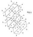
- Fig. 5 shows a structure that is different from those of the other Embodiments by mutually under a protruding, blunt Angle inclined vertical boundary planes s for the roof edges 7 differs. This offers with a staggered assembly individual sub-bodies a and b an advantageous nesting, as with full lines is shown. In an aligned sequence (dash-dotted indicated) an additional light opening 12 between the sub-structures a and b preserved in the roof area.
- the invention is of course not based on the illustrated embodiments limited, since buildings in multiple designs from pairs interconnected building boards according to the invention are erected can. So z. B. also the building opening between the roof edges 7 two interconnected building boards 1 for connecting another Building board pair are used, the longer sides 4 in this case the Length of the roof edges 7 of the first pair of plates must correspond to the roof edges can be connected.
Landscapes
- Engineering & Computer Science (AREA)
- Architecture (AREA)
- Civil Engineering (AREA)
- Structural Engineering (AREA)
- Physics & Mathematics (AREA)
- Electromagnetism (AREA)
- Load-Bearing And Curtain Walls (AREA)
- Buildings Adapted To Withstand Abnormal External Influences (AREA)
- Building Environments (AREA)
- Organic Low-Molecular-Weight Compounds And Preparation Thereof (AREA)
- Rod-Shaped Construction Members (AREA)
Abstract
Description
Die Erfindung bezieht sich auf einen Baukörper, bestehend aus auf einer Grundfläche abgestützten, Dachflächen ergebenden, selbsttragenden und miteinander entlang ihrer aneinanderstoßenden Seiten verbundenen Bauplatten, die von einer Spitze abfallende Pyramidenflächen mit einer von der Spitze zur Grundfläche durchgehenden längeren und einer mit Abstand oberhalb der Grundfläche endenden, kürzeren Seite formen, zwischen der und der Grundfläche die Bauplatten einen quer zur kürzeren Seite entlang einer vertikalen Begrenzungsebene verlaufenden Dachrand bilden, wobei für die Baukörperöffnung im Bereich der Dachränder von miteinander entlang der kürzeren Seite verbundenen Bauplatten eine Abschlußwand mit Tür- bzw. Fensteröffnungen vorgesehen ist.The invention relates to a structure consisting of a Base area supported, roof areas resulting, self-supporting and building boards joined together along their abutting sides, the pyramid surfaces sloping from a top with one from the top to the top Continuous longer base area and one at a distance above the Shaping the shorter side of the base, between the and the base the building boards one across the shorter side along a vertical Form the delimiting roof edge, being for the building opening in the area of the roof edges from each other along the shorter side connected building boards an end wall with door or window openings is provided.
Um aus vorgefertigten, einfach zusammensetzbaren Bauplatten einen Baukörper errichten zu können, ist es bekannt (US 3 714 749 A), über einer Grundfläche in Form eines regelmäßigen Vieleckes dreieckige Bauplatten so aufzustellen, daß jeder Vieleckseite zwei Bauplatten zugeordnet sind, deren längste Seite jeweils von einem Ende der Vieleckseite zu einer gemeinsamen Spitze des Baukörpers führt, während die von der Spitze abfallende kürzeren Seiten dieser einander paarweise zugeordneten Bauplatten miteinander in Verbindung stehen, so daß sich zwischen diesen dreieckförmigen Bauplatten eine von der Spitze abfallende, giebelartige Dachfläche ergibt, deren gegen die Enden der Vieleckseite der Grundfläche hin abfallenden Dachränder eine Baukörperöffnung begrenzen. die durch eine Wand mit Tür- bzw. Fensteröffnungen verschlossen werden kann. Die jeder Vieleckseite der Grundfläche zugeordneten, giebelartigen Dachflächen müssen miteinander entlang der von der Spitze zu den Ecken der Grundfläche durchgehenden Seiten der Bauplatten verbunden werden, um eine selbsttragende Konstruktion zu erhalten, was die Errichtung solcher Baukörper erschwert. Außerdem ergibt sich aufgrund der miteinander verbundenen Hypothenusen der dreieckförmigen Bauplatten ein pyramidenförmiger Grundkörper, der im Bereich seiner Seitenflächen durch aufgesetzte, abfallende Giebeldächer erweitert wird, so daß eine solche Konstruktion eine für die Schaffung beispielsweise von Wohnraum ungünstige Raumaufteilung mit sich bringt.To build a building from prefabricated, easily assembled building boards To be able to build, it is known (US 3,714,749 A), over a base area to set up triangular building boards in the form of a regular polygon, that each polygon side is assigned two building boards, the longest side each from one end of the polygonal side to a common tip of the Building leads, while the shorter sides sloping from the top of this building boards assigned to one another in pairs are connected to one another, so that between these triangular building boards one from the top sloping, gable-like roof surface results in that against the ends of the polygonal side an opening in the building's base sloping towards the base limit. which are closed by a wall with door or window openings can be. The gable-like elements assigned to each polygonal side of the base area Roof areas must be along the from top to the top Corners of the base connected through the sides of the building boards to get a self-supporting construction, which is the erection such structure difficult. It also arises due to each other connected hypotenuses of the triangular building boards a pyramid-shaped Base body, which in the area of its side surfaces by attached, sloping Gable roofs are expanded, so that such a construction is one for the creation of unfavorable floor plans, for example brings itself.
Der Erfindung liegt somit die Aufgabe zugrunde, einen Baukörper der eingangs geschilderten Art mit einfachen Mitteln so auszugestalten, daß eine stabile, einfach zu errichtende Konstruktion mit einer vorteilhaften Raumaufteilung insbesondere für Wohnzwecke erhalten wird.The invention is therefore based on the object, a structure of the beginning to be described with simple means in such a way that a stable, easy-to-erect construction with an advantageous floor plan especially for residential purposes.
Die Erfindung löst die gestellte Aufgabe dadurch, daß die Bauplatten die Grundform eines Viereckes aufweisen und sich über den zur Grundfläche parallelen Stützrand zwischen der längeren, von der Spitze zur Grundfläche durchgehenden Seite und dem Dachrand auf der Grundfläche abstützen.The invention solves this problem in that the building boards have the basic shape of a square and over the parallel to the base Supporting edge between the longer, continuous from the top to the base Support the side and the roof edge on the base.
Durch den zur Grundfläche parallelen Stützrand jeder vierseitigen Bauplatte, über den sich die Bauplatten auf der Grundfläche abstützen, wird bereits mit Hilfe von zwei entlang der kürzeren ihrer von der Spitze abfallenden Seiten miteinander verbundenen Bauplatten eine stabile Konstruktion erhalten, so daß die Errichtung von Baukörpern aus solchen paarweise miteinander verbundenen Bauplatten einfach und mit einem geringen Arbeitsaufwand vorgenommen werden kann. Die Stabilität des gesamten Baukörpers wird zusätzlich durch die Verbindung aneinandergereihter Bauplattenpaare jweils entlang der längeren, von der Spitze zur Grundfläche durchgehenden Seite der aneinanderstoßenden Bauplatten erheblich vergrößert, was für den gesamten Baukörper besonders vorteilhafte statische Verhältnisse schafft. Dazu kommt, daß die Bauplatten die Flächen einer gemeinsamen Pyramide mit abgeschnittenen Eckbereichen bilden. Es entfallen daher die für eine gute Raumausnützung für Wohnzwecke unvorteilhaften Pyramidenecken zumindest teilweise, wodurch trotz der von der Spitze zur Grundfläche abfallenden Bauplatten ein in bezug auf die verbaute Grundfläche günstiges Raumangebot erhalten wird. Die durch die abgeschnittenen Pyramidenecken erhaltenen giebelartigen Baukörperöffnungen können in einfacher Weise durch mit Fenster- bzw. Türöffnungen versehenen Wänden verschlossen werden, wie dies an sich bekannt ist. Mit Hilfe entsprechend großer Lichtdurchtrittsöffnungen in diesen Abschlußwänden lassen sich auch vorteilhafte Tageslichtverhältnisse im inneren des Baukörpers erzielen. Bei einer entsprechend großen Grundrißfläche kann der Innenraum durch Trennwände in Einzelräume unterteilt werden. Selbstverständlich ist es auch möglich, ein oder mehrere Zwischengeschosse einzuziehen.Due to the supporting edge of each four-sided building board parallel to the base, with which the building boards are supported on the base area is already included Help from two along the shorter of their sloping sides interconnected building boards get a stable construction, so that the erection of structures from those connected in pairs Building boards made easily and with little effort can be. The stability of the entire building structure is further enhanced by the Connection of pairs of building boards lined up along the longer, from the top to the base, the side of the abutting side Building boards significantly enlarged, which is particularly true for the entire building creates advantageous static conditions. In addition, the building boards the Form surfaces of a common pyramid with cut off corner areas. Therefore, those that are disadvantageous for a good use of space for residential purposes are eliminated Pyramid corners at least partially, which despite the top slabs falling towards the base in relation to the installed base favorable space is obtained. The by the cut off Pyramid-like gable-like openings in the building can be obtained more easily Closed by walls with window or door openings be, as is known per se. With the help of appropriately large Light passage openings in these end walls can also be advantageous Achieve daylight conditions inside the building. With one accordingly The interior space can be large thanks to partitions in individual rooms be divided. Of course, it is also possible to use one or more To move in mezzanines.
Obwohl die Grundrißfläche der Pyramide ein geradzahliges Vieleck mit einer verschiedenen Anzahl von Ecken darstellen kann, ergeben sich besonders vorteilhafte Konstruktionsbedingungen, wenn vier einander paarweise zugeordnete Bauplatten einerseits entlang ihrer längeren Seite und anderseits entlang ihrer kürzeren Seite miteinander zu einer vierseitigen Pyramide verbunden sind, so daß sich auf einander gegenüberliegenden Seiten giebelartige Baukörperöffnungen ergeben, die durch entsprechende Wände mit Fenster- und Türöffnungen abgeschlossen werden können. Um größere Baukörper mit zwei oder mehreren voneinander getrennten Wohneinheiten zu schaffen, können wenigstens zwei Teilbaukörper aus paarweise einander zugeordneten Bauplatten im Bereich zweier einander zugekehrter Baukörperöffnungen miteinander verbunden werden. Überlappen dabei die einander zugekehrten Baukörperöffnungen der Teilbaukörper einander teilweise, so ergibt sich zwischen den unmittelbar aneinanderstoßenden Teilbaukörpern ein wirksamer Sichtschutz, weil die Fenster- bzw. Türöffnungen der Abschlußwände außerhalb des Überlappungsbereiches jeweils nur einen Blick entlang der Dachflächen des anschließenden Teilbaukörpers freigeben. Although the floor plan of the pyramid is an even polygon with a can represent different number of corners, result in particular advantageous design conditions if four are assigned to each other in pairs Building boards on the one hand along their longer side and on the other hand along their shorter side are connected to a four-sided pyramid, so that there are gable-like building openings on opposite sides result from corresponding walls with window and door openings can be completed. To larger structures with two or to create several separate units, at least two partial building blocks made of building boards assigned to one another in pairs Area of two mutually facing structural openings connected to one another will. The openings facing each other overlap the partial structure partially to each other, so there is between the effective partial protection against directly adjoining partial structures, because the window or door openings of the end walls outside the overlap area just a glance along the roof surfaces of the next Release part of the building.
In besonderen Fällen kann es vorteilhaft sein, die Bauplatten im Bereich der längeren Seite und des Dachrandes über den Stützrand hinaus zu tragenden Stützen zu verlängern, um zwischen dem Baukörper und der Grundfläche einen entsprechenden Abstand zu schaffen, sei es zur Berücksichtigung einer sonst nicht bebaubaren Grundfläche oder zum Bereitstellen eines zusätzlichen Raumes unterhalb des Baukörpers.In special cases, it can be advantageous to use the building boards in the area of longer side and the roof edge to be carried beyond the supporting edge Extend supports to one between the structure and the base to create the appropriate distance, be it to take account of an otherwise non-buildable floor space or to provide additional space below the building.
Schließen die die Dachränder begrenzenden Vertikalebenen miteinander einen einspringenden stumpfen Winkel ein, so ergeben sich hinsichtlich des Zusammenbaus von Teilbaukörpern vorteilhafte Bedingungen, weil bei einer gegenseitigen Versetzung der Teilbaukörper gewissermaßen eine Verzahnung im Bereich der gegengleich geneigten Begrenzungsebenen und bei einer fluchtenden Aneinanderreihung eine Lichtöffnung im Dachbereich zwischen den Teilbaukörpern erhalten wird.Include the vertical planes that delimit the roof edges protruding obtuse angles result in the assembly of partial structures advantageous conditions, because in a mutual Relocation of the partial structure, a kind of interlocking in Area of the oppositely inclined boundary planes and with an aligned one Stringing together a light opening in the roof area between the sub-structures is obtained.
In der Zeichnung ist der Erfindungsgegenstand beispielsweise dargestellt. Es zeigen
- Fig. 1
- einen erfindungsgemäßen Baukörper in einem schematischen Schaubild.
- Fig. 2
- diesen Baukörper in einer Draufsicht.
- Fig. 3
- einen aus zwei Teilbaukörpern zusammengesetzten Baukörper in einem vereinfachten Schaubild.
- Fig. 4
- eine weitere Ausführungsform eines erfindungsgemäßen Baukörpers ebenfalls in einem Schaubild und
- Fig. 5
- eine der Fig. 2 entsprechende Darstellung einer weiteren Konstruktionsvariante.
- Fig. 1
- a building structure according to the invention in a schematic diagram.
- Fig. 2
- this structure in a top view.
- Fig. 3
- a structure composed of two partial structures in a simplified diagram.
- Fig. 4
- a further embodiment of a structure according to the invention also in a diagram and
- Fig. 5
- a representation of another design variant corresponding to FIG. 2.
Der in den Fig. 1 und 2 dargestellte Baukörper ist aus paarweise einander
zugeordneten Bauplatten 1 und 2 zusammengesetzt, die von einer Spitze 3
abfallende Pyramidenflächen bilden. Diese sich durch die Bauplatten 1 und 2
ergebende Hüllpyramide ist in der Fig. 1 mit dünnen Linien eingezeichnet. Man
erkennt, daß jede Bauplatte 1, 2 eine von der Spitze 3 zur Grundfläche durchgehende,
längere Seite 4 und eine mit Abstand oberhalb der Grundfläche
endende, kürzere Seite 5 aufweist, die entsteht, wenn die Pyramidenecken 6
durch quer zu den Seiten 5 verlaufende, vertikale Begrenzungsebenen s abgeschnitten
werden, wie sie in der Fig. 2 angedeutet sind, so daß die je eine
Dachfläche bildenden Bauplatten 1 von der kürzeren Seite 5 zur Grundfläche
abfallende Dachränder 7 formen, zwischen denen eine giebelartige Baukörperöffnung
entsteht. Diese Baukörperöffnung kann durch eine mit Fenster- bzw.
Türöffnungen versehene Wand 8 abgeschlossen werden, um einen allseits
geschlossenen Baukörper zu erhalten.The structure shown in FIGS. 1 and 2 is in pairs from each other
assigned
Zwischen den Dachrändern 7, die nicht durchgehend gerade verlaufen müssen,
und der längeren Seite 4 weisen die Bauplatten 1, 2 einen Stützrand 9 auf, der
bodenparallel verläuft und zur Lastabtragung auf der Grundfläche aufruht. Wie
dem Grundriß gemäß der Fig. 2 entnommen werden kann, bilden die durch die
Stützränder 9 der Bauplatten 1 und 2 bestimmten Grundlinien der Pyramide
einen stumpfen Winkel, um besonders vorteilhafte Innenraumverhältnisse zu
schaffen. Die in Richtung der kürzeren Seiten 5 verlaufende längere Diagonale
der gleichseitigen, viereckigen Pyramide ergibt eine flachere Neigung der
kürzeren Seiten 5 der miteinander verbundenen Bauplatten 1 und 2, was bei
einer vorgegebenen Länge des Stützrandes 9 eine größere Giebelhöhe für die
Baukörperöffnung und damit eine günstigere Raumausnützung bedingt.Between the
Die Errichtung eines solchen Baukörpers ist besonders einfach mit Hilfe von
spiegelbildlich gleichen Bauplatten 1 und 2 durchzuführen, weil diese Bauplatten
1 und 2 lediglich aufgestellt und entlang ihrer kürzeren Seite 5 miteinander zu
verbinden sind, um eine für sich stabile Baueinheit zu erhalten, an die entlang
der längeren Seiten 4 ein weiteres Bauplattenpaar 1 und 2 angeschlossen
werden kann.The erection of such a structure is particularly simple with the help of
perform mirror images of the
Wie der Fig. 3 zu entnommen ist, wird es in weiterer Ausbildung der Erfindung
möglich, aus untereinander übereinstimmenden Teilbaukörpern a und b einen
Gesamtbaukörper zusammenzusetzen, der je Teilbaukörper a bzw. b eine
gesonderte Wohneinheit umfassen kann. Diese Teilbaukörper a und b entsprechen
dem Baukörper nach der Fig. 1, wobei die Anordnung so getroffen ist,
daß die beiden Teilbaukörper a und b im Bereich einander gegenüberliegender
Baukörperöffnungen aneinanderstoßen, die sich teilweise überlappen. Außerhalb
des Überlappungsbereiches sind die Fenster- und Türöffnungen der Abschlußwände
8 an den jeweils anschließenden Teilbaukörper a bzw. b vorbeigerichtet,
so daß sich trotz des unmittelbaren Zusammenschlusses zweier solcher Teilbaukörper
a und b ein guter Sichtschutz ergibt. In der Fig. 2 ist ein solcher Zusammenbau
aus zwei Teilbaukörpern strichpunktiert angedeutet, wobei ersichtlich
ist, daß die Teilbaukörper a und b eine gemeinsame Begrenzungsebene s
aufweisen.As can be seen from Fig. 3, it is in a further embodiment of the invention
possible from a matching sub-structures a and b
Assemble overall building structure, one for each building structure a or b
can include separate housing unit. These sub-structures correspond to a and b
the structure of FIG. 1, the arrangement being made
that the two sub-structures a and b in the area opposite each other
Butting structure openings that partially overlap. Outside
of the overlap area are the window and door openings of the
Die Ausführungsform nach der Fig. 4 unterscheidet sich von der Ausführungsform
des Baukörpers gemäß der Fig. 1 lediglich dadurch, daß die Bauplatten 1
und 2 im Bereich ihrer längeren Seite 4 und im Bereich des Dachrandes 7 über
den Stützrand 9 hinaus zu tragenden Stützen 10 verlängert sind, so daß der
eigentliche Baukörper mit Abstand oberhalb der Grundfläche errichtet werden
kann. Um von der Grundfläche zum Baukörper zu gelangen, ist daher der
Giebelseite ein Aufgang 11 vorgelagert. Diese Ausführungsform erlaubt beispielsweise
die Bebauung von sumpfigem oder sonst nicht tragfähigem Gelände,
wenn die Stützen 10 entsprechend verankert werden können. Außerdem
ergibt sich unterhalb des Baukörpers ein zusätzlicher Raum, der für verschiedene
Zwecke genutzt und verbaut werden kann.The embodiment according to FIG. 4 differs from the embodiment
of the structure according to FIG. 1 only in that the building boards 1st
and 2 in the area of their
Schließlich zeigt die Fig. 5 einen Baukörper, der sich von denen der anderen
Ausführungsbeispiele durch zueinander unter einem einspringenden, stumpfen
Winkel geneigten vertikalen Begrenzungsebenen s für die Dachränder 7 unterscheidet.
Dies bietet bei einem gegeneinader versetzten Zusammenbau
einzelner Teilkörper a und b eine vorteilhafte Verschachtelung, wie dies mit
vollen Linien dargestellt ist. Bei einer fluchtenden Aneinanderreihung (strichpunktiert
angedeutet) wird eine zusätzliche Lichtöffnung 12 zwischen den Teilbaukörpern
a und b im Dachbereich erhalten. Finally, Fig. 5 shows a structure that is different from those of the other
Embodiments by mutually under a protruding, blunt
Angle inclined vertical boundary planes s for the
Die Erfindung ist selbstverständlich nicht auf die dargestellten Ausführungsbeispiele
beschränkt, da ja Baukörper in vielfacher Ausgestaltung aus paarweise
miteinander verbundenen, erfindungsgemäßen Bauplatten errichtet werden
können. So kann z. B. auch die Baukörperöffnung zwischen den Dachrändern
7 zweier miteinander verbundener Bauplatten 1 zum Anschluß eines weiteren
Bauplattenpaares benützt werden, deren längere Seiten 4 in diesem Fall der
Länge der Dachränder 7 des ersten Plattenpaares entsprechen müssen, um mit
dessen Dachrändern verbunden werden zu können.The invention is of course not based on the illustrated embodiments
limited, since buildings in multiple designs from pairs
interconnected building boards according to the invention are erected
can. So z. B. also the building opening between the
Claims (6)
- A structural member comprising self-supporting structural panels (1, 2) which rest on a base surface, form roof surfaces and are interconnected along their abutting sides (4, 5) and form pyramid surfaces sloping down from a tip (3) and having a longer side (4) extending from the tip (3) to the base surface and a shorter side (5) ending at a distance above the base surface, and between the shorter side and the base surface the structural panels (1, 2) form a roof edge (7) extending transversely to the shorter side (5) along a vertical boundary plane (s), wherein a closure wall (8) with door and/or window openings is provided for the structural-member opening in the region of the roof edges (7) of structural panels (1, 2) interconnected along the shorter sides (5),
characterised in that the structural panels (1, 2) have a basically polygonal shape and abut one another on the base surface via a supporting edge (9) parallel to the base surface between the roof edge (7) and the longer side (4) extending from the tip (3) to the base. - A structural member according to claim 1,
characterised in that four structural panels (1, 2) associated with one another in pairs are interconnected along their longer side (4) on the one hand and along their shorter side (5) on the other hand. - A structural member according to claim 1 or 2,
characterised in that at least two component structural members (a, b) made up of pairs of associated structural panels (1, 2) are interconnected in the region where two structural member openings face one another. - A structural member according to claim 3,
characterised in that the facing openings of the component structural members (a, b) partially overlap. - A structural member according to any of claims 1 to 4, characterised in that the structural panels (1, 2) are prolonged beyond the supporting edge (9) to form load-bearing supports (10) in the region of the longer side and the roof edge (7).
- A structural member according to any of claims 1 to 5, characterised in that the vertical planes (s) bounding the roof edges (7) together include a reentrant obtuse angle.
Applications Claiming Priority (3)
| Application Number | Priority Date | Filing Date | Title |
|---|---|---|---|
| US08/397,902 US5566514A (en) | 1995-03-03 | 1995-03-03 | Self-supporting building structure |
| US397902 | 1995-03-03 | ||
| PCT/AT1996/000036 WO1996027715A1 (en) | 1995-03-03 | 1996-03-01 | Building structure |
Publications (2)
| Publication Number | Publication Date |
|---|---|
| EP0813638A1 EP0813638A1 (en) | 1997-12-29 |
| EP0813638B1 true EP0813638B1 (en) | 1998-11-25 |
Family
ID=23573143
Family Applications (1)
| Application Number | Title | Priority Date | Filing Date |
|---|---|---|---|
| EP96902803A Expired - Lifetime EP0813638B1 (en) | 1995-03-03 | 1996-03-01 | Building structure |
Country Status (9)
| Country | Link |
|---|---|
| US (1) | US5566514A (en) |
| EP (1) | EP0813638B1 (en) |
| AT (1) | ATE173782T1 (en) |
| CZ (1) | CZ290851B6 (en) |
| DE (1) | DE59600872D1 (en) |
| ES (1) | ES2127622T3 (en) |
| GR (1) | GR3029441T3 (en) |
| PL (1) | PL183305B1 (en) |
| WO (1) | WO1996027715A1 (en) |
Cited By (1)
| Publication number | Priority date | Publication date | Assignee | Title |
|---|---|---|---|---|
| CN103758210A (en) * | 2014-01-10 | 2014-04-30 | 东南大学 | Full-folding structure for implementing free-form surfaces and method thereof |
Families Citing this family (8)
| Publication number | Priority date | Publication date | Assignee | Title |
|---|---|---|---|---|
| EP1200686B1 (en) * | 1999-05-21 | 2004-04-28 | Woodcraft, David Charles | Kit of structural building parts |
| US6202364B1 (en) * | 1999-11-08 | 2001-03-20 | Bernard Fredette | Prefabricated self-supporting building structure |
| US8544216B1 (en) * | 2010-08-25 | 2013-10-01 | David Hazlett | Portable corrugated plastic shelter |
| ITPD20110131A1 (en) * | 2011-04-26 | 2012-10-27 | Vidal Caterina | MODULAR LIVING UNIT |
| US8615934B1 (en) * | 2011-10-07 | 2013-12-31 | Stephen C. Webb | Panelized portable shelter |
| TW202026504A (en) * | 2018-11-21 | 2020-07-16 | 美商奧托德里克控股公司 | Core for building |
| US11555305B2 (en) | 2020-06-24 | 2023-01-17 | Gisue Hariri | Foldable shelter pod and method for preparing a foldable shelter pod |
| USD964594S1 (en) | 2020-06-24 | 2022-09-20 | Gisue Hariri | Folding pod/shelter |
Family Cites Families (19)
| Publication number | Priority date | Publication date | Assignee | Title |
|---|---|---|---|---|
| US1599213A (en) * | 1926-09-07 | Sixte aemand coupal | ||
| US2071093A (en) * | 1933-11-07 | 1937-02-16 | Budd Edward G Mfg Co | Sheet metal dome for planetarium or the like |
| US2835931A (en) * | 1954-07-06 | 1958-05-27 | Sterkin Albert | Foldable shelter |
| US3230673A (en) * | 1963-04-08 | 1966-01-25 | Robert P Gersin | Modular building |
| US3346998A (en) * | 1964-06-29 | 1967-10-17 | Donal P Nelson | Structures formed exclusively of flat panelled right triangular building components |
| FR1453984A (en) * | 1965-08-16 | 1966-09-30 | Improvements made to prefabricated buildings | |
| US3759277A (en) * | 1971-04-16 | 1973-09-18 | C Glade | Portable shelter |
| US3714749A (en) * | 1971-09-02 | 1973-02-06 | Instant Structures Inc | Portable building construction |
| US3807104A (en) * | 1972-05-31 | 1974-04-30 | Reynolds Metals Co | Foldable portable structure |
| US4073105A (en) * | 1972-11-29 | 1978-02-14 | Daugherty Charles R | Temporary structure |
| US3983665A (en) * | 1975-09-24 | 1976-10-05 | Burkin Homes Corporation | Foldable and transportable home |
| US4064662A (en) * | 1976-09-29 | 1977-12-27 | Toole John M O | Collapsible tetrahedral structure |
| US4413452A (en) * | 1979-10-17 | 1983-11-08 | Wilkinson Don G | Building structure |
| US4285174A (en) * | 1979-11-23 | 1981-08-25 | Knight Brian V | Building structure |
| US4672779A (en) * | 1981-07-02 | 1987-06-16 | Boyd Clarence J | Portable shelter |
| IL75983A (en) * | 1985-07-31 | 1986-10-31 | Abraham Nahmias | Light-weight collapsible shelter |
| GB2225358A (en) * | 1987-06-04 | 1990-05-30 | Nisar Sayed | Portable foldable shelter |
| US4937987A (en) * | 1989-03-10 | 1990-07-03 | Runyon John F | Temporary building structure |
| US4951432A (en) * | 1989-11-27 | 1990-08-28 | Wilkinson Don G | Folding building structure |
-
1995
- 1995-03-03 US US08/397,902 patent/US5566514A/en not_active Expired - Lifetime
-
1996
- 1996-03-01 ES ES96902803T patent/ES2127622T3/en not_active Expired - Lifetime
- 1996-03-01 CZ CZ19972712A patent/CZ290851B6/en not_active IP Right Cessation
- 1996-03-01 AT AT96902803T patent/ATE173782T1/en active
- 1996-03-01 PL PL96322081A patent/PL183305B1/en unknown
- 1996-03-01 WO PCT/AT1996/000036 patent/WO1996027715A1/en active IP Right Grant
- 1996-03-01 DE DE59600872T patent/DE59600872D1/en not_active Expired - Lifetime
- 1996-03-01 EP EP96902803A patent/EP0813638B1/en not_active Expired - Lifetime
-
1999
- 1999-02-17 GR GR990400526T patent/GR3029441T3/en unknown
Cited By (2)
| Publication number | Priority date | Publication date | Assignee | Title |
|---|---|---|---|---|
| CN103758210A (en) * | 2014-01-10 | 2014-04-30 | 东南大学 | Full-folding structure for implementing free-form surfaces and method thereof |
| CN103758210B (en) * | 2014-01-10 | 2016-06-08 | 东南大学 | A kind of complete foldable structure for realizing free form surface and method thereof |
Also Published As
| Publication number | Publication date |
|---|---|
| PL322081A1 (en) | 1998-01-05 |
| GR3029441T3 (en) | 1999-05-28 |
| US5566514A (en) | 1996-10-22 |
| CZ290851B6 (en) | 2002-10-16 |
| DE59600872D1 (en) | 1999-01-07 |
| PL183305B1 (en) | 2002-06-28 |
| WO1996027715A1 (en) | 1996-09-12 |
| ATE173782T1 (en) | 1998-12-15 |
| ES2127622T3 (en) | 1999-04-16 |
| CZ271297A3 (en) | 1998-02-18 |
| EP0813638A1 (en) | 1997-12-29 |
Similar Documents
| Publication | Publication Date | Title |
|---|---|---|
| DE3104735C2 (en) | ||
| DE1609784C3 (en) | ||
| EP0813638B1 (en) | Building structure | |
| DE2160216B1 (en) | Multi-part profile bar for the production of skeleton structures with infill panels | |
| DE60101794T2 (en) | ADDITIONAL DEVICE FOR A MODULAR ELEMENT FOR CAVES AND FLOOR STRUCTURES | |
| EP0517117B1 (en) | Wooden plant container | |
| EP0120292A2 (en) | Construction element | |
| AT17732U2 (en) | Kit for a tool shed | |
| DE3203366A1 (en) | Modular building system | |
| DE4237325C2 (en) | Room cell arrangement, especially a mobile building with a multi-storey construction | |
| DE2345602C2 (en) | Building construction | |
| DE4226735A1 (en) | Room cell made of interlocking wall elements | |
| DE3730679C2 (en) | ||
| DE202021004208U1 (en) | Kit for a tool shed | |
| DE3304668A1 (en) | Sheet-like supporting structure and constructional elements for its production | |
| DE102004060288B4 (en) | building module | |
| DE10135389A1 (en) | C-section | |
| DE3933392A1 (en) | Self-supporting expandable constructional plate - has three=dimensional lattice work structure between bottom portion and strip | |
| DE3625404A1 (en) | Multi-part wooden support | |
| AT17369U1 (en) | Kit for a tool shed | |
| DE8320588U1 (en) | COMPOSTING DEVICE | |
| DE3027019C2 (en) | ||
| DE4336077A1 (en) | Dry-construction partition wall | |
| DE102020101353A1 (en) | Support element | |
| DE1658789C (en) | Wall made of prefabricated, mutually connected, load-bearing wall elements |
Legal Events
| Date | Code | Title | Description |
|---|---|---|---|
| PUAI | Public reference made under article 153(3) epc to a published international application that has entered the european phase |
Free format text: ORIGINAL CODE: 0009012 |
|
| 17P | Request for examination filed |
Effective date: 19970822 |
|
| AK | Designated contracting states |
Kind code of ref document: A1 Designated state(s): AT BE CH DE DK ES FI FR GB GR IE IT LI LU MC NL PT SE |
|
| GRAG | Despatch of communication of intention to grant |
Free format text: ORIGINAL CODE: EPIDOS AGRA |
|
| 17Q | First examination report despatched |
Effective date: 19980218 |
|
| GRAG | Despatch of communication of intention to grant |
Free format text: ORIGINAL CODE: EPIDOS AGRA |
|
| GRAH | Despatch of communication of intention to grant a patent |
Free format text: ORIGINAL CODE: EPIDOS IGRA |
|
| GRAH | Despatch of communication of intention to grant a patent |
Free format text: ORIGINAL CODE: EPIDOS IGRA |
|
| GRAA | (expected) grant |
Free format text: ORIGINAL CODE: 0009210 |
|
| AK | Designated contracting states |
Kind code of ref document: B1 Designated state(s): AT BE CH DE DK ES FI FR GB GR IE IT LI LU MC NL PT SE |
|
| PG25 | Lapsed in a contracting state [announced via postgrant information from national office to epo] |
Ref country code: GB Free format text: LAPSE BECAUSE OF NON-PAYMENT OF DUE FEES Effective date: 19981125 Ref country code: FI Free format text: LAPSE BECAUSE OF NON-PAYMENT OF DUE FEES Effective date: 19981125 |
|
| REF | Corresponds to: |
Ref document number: 173782 Country of ref document: AT Date of ref document: 19981215 Kind code of ref document: T |
|
| REG | Reference to a national code |
Ref country code: CH Ref legal event code: EP |
|
| REF | Corresponds to: |
Ref document number: 59600872 Country of ref document: DE Date of ref document: 19990107 |
|
| REG | Reference to a national code |
Ref country code: IE Ref legal event code: FG4D Free format text: GERMAN |
|
| ITF | It: translation for a ep patent filed |
Owner name: STUDIO INGG. FISCHETTI & WEBER |
|
| PG25 | Lapsed in a contracting state [announced via postgrant information from national office to epo] |
Ref country code: PT Free format text: LAPSE BECAUSE OF FAILURE TO SUBMIT A TRANSLATION OF THE DESCRIPTION OR TO PAY THE FEE WITHIN THE PRESCRIBED TIME-LIMIT Effective date: 19990225 Ref country code: DK Free format text: LAPSE BECAUSE OF FAILURE TO SUBMIT A TRANSLATION OF THE DESCRIPTION OR TO PAY THE FEE WITHIN THE PRESCRIBED TIME-LIMIT Effective date: 19990225 |
|
| PG25 | Lapsed in a contracting state [announced via postgrant information from national office to epo] |
Ref country code: LU Free format text: LAPSE BECAUSE OF NON-PAYMENT OF DUE FEES Effective date: 19990301 |
|
| ET | Fr: translation filed | ||
| REG | Reference to a national code |
Ref country code: CH Ref legal event code: NV Representative=s name: DIPL.-ING. W. STEUDTNER |
|
| REG | Reference to a national code |
Ref country code: ES Ref legal event code: FG2A Ref document number: 2127622 Country of ref document: ES Kind code of ref document: T3 |
|
| GBV | Gb: ep patent (uk) treated as always having been void in accordance with gb section 77(7)/1977 [no translation filed] |
Effective date: 19981125 |
|
| PG25 | Lapsed in a contracting state [announced via postgrant information from national office to epo] |
Ref country code: IE Free format text: LAPSE BECAUSE OF NON-PAYMENT OF DUE FEES Effective date: 19990820 |
|
| PG25 | Lapsed in a contracting state [announced via postgrant information from national office to epo] |
Ref country code: MC Free format text: LAPSE BECAUSE OF NON-PAYMENT OF DUE FEES Effective date: 19990930 |
|
| PLBE | No opposition filed within time limit |
Free format text: ORIGINAL CODE: 0009261 |
|
| STAA | Information on the status of an ep patent application or granted ep patent |
Free format text: STATUS: NO OPPOSITION FILED WITHIN TIME LIMIT |
|
| REG | Reference to a national code |
Ref country code: IE Ref legal event code: FD4D |
|
| 26N | No opposition filed | ||
| REG | Reference to a national code |
Ref country code: CH Ref legal event code: PCAR Free format text: PATENTANWALTSBUREAU STEUDTNER;AHORNWEG 12;5702 NIEDERLENZ (CH) |
|
| REG | Reference to a national code |
Ref country code: CH Ref legal event code: PCAR Free format text: PATENTANWALTSBUERO STEUDTNER;AHORNWEG 6;5702 NIEDERLENZ (CH) |
|
| PGFP | Annual fee paid to national office [announced via postgrant information from national office to epo] |
Ref country code: NL Payment date: 20140326 Year of fee payment: 19 Ref country code: CH Payment date: 20140306 Year of fee payment: 19 Ref country code: SE Payment date: 20140311 Year of fee payment: 19 |
|
| PGFP | Annual fee paid to national office [announced via postgrant information from national office to epo] |
Ref country code: ES Payment date: 20140211 Year of fee payment: 19 Ref country code: AT Payment date: 20140318 Year of fee payment: 19 Ref country code: IT Payment date: 20140221 Year of fee payment: 19 Ref country code: GR Payment date: 20140227 Year of fee payment: 19 |
|
| PGFP | Annual fee paid to national office [announced via postgrant information from national office to epo] |
Ref country code: BE Payment date: 20140303 Year of fee payment: 19 |
|
| REG | Reference to a national code |
Ref country code: CH Ref legal event code: PCAR Free format text: NEW ADDRESS: ALBULAGASSE 8, 5200 BRUGG/AG (CH) |
|
| PGFP | Annual fee paid to national office [announced via postgrant information from national office to epo] |
Ref country code: FR Payment date: 20140328 Year of fee payment: 19 |
|
| PGFP | Annual fee paid to national office [announced via postgrant information from national office to epo] |
Ref country code: DE Payment date: 20150402 Year of fee payment: 20 |
|
| REG | Reference to a national code |
Ref country code: CH Ref legal event code: PL |
|
| REG | Reference to a national code |
Ref country code: AT Ref legal event code: MM01 Ref document number: 173782 Country of ref document: AT Kind code of ref document: T Effective date: 20150301 |
|
| PG25 | Lapsed in a contracting state [announced via postgrant information from national office to epo] |
Ref country code: SE Free format text: LAPSE BECAUSE OF NON-PAYMENT OF DUE FEES Effective date: 20150302 |
|
| REG | Reference to a national code |
Ref country code: SE Ref legal event code: EUG |
|
| REG | Reference to a national code |
Ref country code: NL Ref legal event code: MM Effective date: 20150401 |
|
| REG | Reference to a national code |
Ref country code: GR Ref legal event code: ML Ref document number: 990400526 Country of ref document: GR Effective date: 20151002 |
|
| PG25 | Lapsed in a contracting state [announced via postgrant information from national office to epo] |
Ref country code: IT Free format text: LAPSE BECAUSE OF NON-PAYMENT OF DUE FEES Effective date: 20150301 |
|
| REG | Reference to a national code |
Ref country code: FR Ref legal event code: ST Effective date: 20151130 |
|
| PG25 | Lapsed in a contracting state [announced via postgrant information from national office to epo] |
Ref country code: CH Free format text: LAPSE BECAUSE OF NON-PAYMENT OF DUE FEES Effective date: 20150331 Ref country code: LI Free format text: LAPSE BECAUSE OF NON-PAYMENT OF DUE FEES Effective date: 20150331 Ref country code: GR Free format text: LAPSE BECAUSE OF NON-PAYMENT OF DUE FEES Effective date: 20151002 |
|
| PG25 | Lapsed in a contracting state [announced via postgrant information from national office to epo] |
Ref country code: FR Free format text: LAPSE BECAUSE OF NON-PAYMENT OF DUE FEES Effective date: 20150331 Ref country code: AT Free format text: LAPSE BECAUSE OF NON-PAYMENT OF DUE FEES Effective date: 20150301 |
|
| REG | Reference to a national code |
Ref country code: DE Ref legal event code: R071 Ref document number: 59600872 Country of ref document: DE |
|
| REG | Reference to a national code |
Ref country code: ES Ref legal event code: FD2A Effective date: 20160427 |
|
| PG25 | Lapsed in a contracting state [announced via postgrant information from national office to epo] |
Ref country code: ES Free format text: LAPSE BECAUSE OF NON-PAYMENT OF DUE FEES Effective date: 20150302 |
|
| PG25 | Lapsed in a contracting state [announced via postgrant information from national office to epo] |
Ref country code: NL Free format text: LAPSE BECAUSE OF NON-PAYMENT OF DUE FEES Effective date: 20150401 |
|
| PG25 | Lapsed in a contracting state [announced via postgrant information from national office to epo] |
Ref country code: BE Free format text: LAPSE BECAUSE OF NON-PAYMENT OF DUE FEES Effective date: 20150331 |