EP0813461B1 - A device for driving inserts into pieces of sheet metal - Google Patents
A device for driving inserts into pieces of sheet metal Download PDFInfo
- Publication number
- EP0813461B1 EP0813461B1 EP96911204A EP96911204A EP0813461B1 EP 0813461 B1 EP0813461 B1 EP 0813461B1 EP 96911204 A EP96911204 A EP 96911204A EP 96911204 A EP96911204 A EP 96911204A EP 0813461 B1 EP0813461 B1 EP 0813461B1
- Authority
- EP
- European Patent Office
- Prior art keywords
- punch
- blank holder
- blades
- inserts
- axis
- Prior art date
- Legal status (The legal status is an assumption and is not a legal conclusion. Google has not performed a legal analysis and makes no representation as to the accuracy of the status listed.)
- Expired - Lifetime
Links
Images


Classifications
-
- B—PERFORMING OPERATIONS; TRANSPORTING
- B21—MECHANICAL METAL-WORKING WITHOUT ESSENTIALLY REMOVING MATERIAL; PUNCHING METAL
- B21J—FORGING; HAMMERING; PRESSING METAL; RIVETING; FORGE FURNACES
- B21J15/00—Riveting
- B21J15/10—Riveting machines
- B21J15/30—Particular elements, e.g. supports; Suspension equipment specially adapted for portable riveters
- B21J15/32—Devices for inserting or holding rivets in position with or without feeding arrangements
-
- B—PERFORMING OPERATIONS; TRANSPORTING
- B21—MECHANICAL METAL-WORKING WITHOUT ESSENTIALLY REMOVING MATERIAL; PUNCHING METAL
- B21J—FORGING; HAMMERING; PRESSING METAL; RIVETING; FORGE FURNACES
- B21J15/00—Riveting
- B21J15/02—Riveting procedures
Definitions
- the present invention relates to a device for driving inserts into pieces of sheet metal according to the preamble of independent claim 1.
- the device is useable for the manufacture of pieces of sheet metal such as casings for electronic devices and the like, furniture elements, etc.
- Inserts for driving into preformed holes in metal sheets may be of various shapes and sizes according to the function they are to perform.
- the most common inserts have holes or shanks, which are generally threaded and form anchorage points for equipment, components and the like.
- a press is normally used to drive inserts into the holes in the metal sheets.
- the press includes a punch and a die which cooperate with one another.
- the inserts are anchored to the sheet when they are force-fitted into the respective holes in the sheet so as to bring about plastic deformation of the portion of the metal sheet adjacent the hole in which the insert is inserted.
- Some existing presses have devices for automatically supplying the insert from a store of inserts to a position in front of a thrust surface of the punch to position the same for insertion.
- a retractable arm places the inserts on an axis of the punch.
- the punch includes means for holding an insert in axially alignment on its end. Once the insert is positively held on the end of the punch, the retractable arm withdraws from the operating area of the punch before the driving of the punch is enabled.
- HP6-C Another type of insert-driving press with automatic supply has been produced by the company Haeger.
- this press known as HP6-C has a punch associated with a blank holder which is coaxial with and slidable relative to the punch.
- the blank holder is connected to a pipe through which the inserts are supplied.
- the objective is solved according to the present invention by a device for driving inserts into pieces of sheet metal comprising the features of the independent claim 1.
- an insert-driving tool which can be rapidly connected to and disconnected from an automatic insert-supply system, and which can work in conjunction with an insert-supply device which does not obstruct the working area.
- the device further comprises a blank holder coaxial with and coupled slidingly on an external surface of the body of the punch, and resilient means for urging the blank holder toward a distal end of the body such that the blank holder forms an extension of the body.
- An internal wall of the blank holder cooperates with the heads of the blades so that axial sliding of the blank holder relative to the punch causes the blades to bend towards the axis of symmetry of the punch.
- the internal wall of the blank holder is tapered towards the axis of symmetry of the punch in a direction from a proximal end of the punch towards the distal end.
- the punch further includes a thrust member coaxial with the body.
- the thrust member is coupled with the body for sliding on an external surface thereof.
- the blades have external surfaces for cooperating with the thrust member so that sliding of the thrust member relative to the body causes the blades to bend towards the axis of symmetry of the punch.
- each of the heads of the blades preferably includes an abutment element
- the blank holder includes an abutment element which cooperates with the abutment elements of the heads to prevent the blank holder from sliding off the punch.
- each of the heads of the blades includes a portion having two abutment surfaces which are fitted in a cavity in the blank holder to prevent the blank holder from sliding axially relative to the punch.
- a distal end of the thrust member forms a free surface which contacts one of the two abutment surfaces of each of the heads of the blades during driving of the thrust member to transmit a thrust force from the thrust member to the heads.
- the blank holder further preferably includes guide elements for guiding the inserts, and through holes along walls of the blank holder.
- the guide elements are preferably flat springs which converge through the through holes of the blank holder toward the axis of symmetry of the punch so as to guide the inserts along the axis.
- the device preferably includes a rod which urges the inserts through the through hole in the punch to supply the inserts for insertion.
- the device according to the invention can easily be replaced automatically and does not involve obstructions due to the insert-supply means in the operating area since the inserts come from the rear end of the punch and perform the last portion of the supply travel which places them in front of the thrust surface in a duct formed inside the punch.
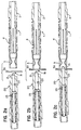
- a punch 1 includes a body 2 which has a tubular, essentially cylindrical shape, for reasons of structural practicality.
- the body 2 may, however, be of any shape, for example, polygonal, and is generally elongate along an axis of symmetry 5.
- the body 2 includes a through-hole 6, which extends along the axis of symmetry 5, which functions as a supply-duct for the inserts to travel through.
- the body further includes an end portion 7 which functions as a shank for connection of the body to an element 45 forming part of a press for driving the inserts.
- the element 45 includes means for the quick coupling and release of the shank 7.
- the duct 6 in the punch 1 is aligned with a duct 46 in the element 45 through which the inserts are fed into the duct 6 in the punch 1.
- the inserts come from automatic loaders (not shown) which guide the inserts to the mouth of the punch in succession.
- the element 45 of the press is movable along the axis of symmetry 5 of the punch and is connected to an actuator (not shown) which generates the force necessary for driving the inserts.
- the body 2 has a plurality of blades 8 which extend parallel to the axis of symmetry 5.
- the blades 8 are formed by a series of slits 13 through the body 2, only one of which can be seen in Fig. 1.
- Blades 8 are integral with the rest of the body 2 , but can bend resiliently under the action of an external force and return to the undeformed position shown in Fig. 1 when the external force ceases to act.
- the frontal surfaces of the individual blades 8 define an annular thrust surface 9 which applies the driving force to the inserts.
- the dimensions of the thrust surface 9 of the punch (particularly its internal diameter) vary as a result of the resilient deformation of the blades 8.
- the supply duct 6 extends the length of the punch 2, and thus through the thrust surface 9.
- Heads 10 at the distal ends of the blades 8 define the thrust surface 9 of the punch 1 on one side.
- the opposite sides of the heads 10 define stop abutments 11, against which the blades 8 are fixed.
- a blank holder 3 is configured to slide against the outer surfaces of the blades 8.
- the blank holder 3 has an internal surface 14 having a frusto-conical intermediate portion and an end portion which has an internal diameter that is smaller than the outside diameter of the heads 10 of the blades 8 in the undeformed condition.
- the blank holder 3 further includes windows 15 formed through the walls thereof.
- Flat springs 16 are anchored to an element 17 and project therefrom. Springs 16 abut the ends of the internal surface 14 and project into the internal space of the blank holder through windows 15. The springs function to guide the insert and/or restrain it in front of the thrust surface 9.
- the element 17 of blank holder 3 is urged against the stop abutments 11 of the blades 8 by a helical compression spring 4 which reacts against an annular shoulder 12 of the body 2.
- Sliding of the blank holder 3 relative to the body 2 of the punch 1 in the direction indicated by the arrow A in Fig. 1 brings about interference and relative sliding between the internal surface 14 of the blank holder and the heads 10 of the blades 8.
- This relative sliding forces the heads 10 to follow the contour of the internal surface 14 and thereby deforms the blades 8 toward the axis of symmetry 5.
- the deformation of the blades 8 causes a reduction in the internal diameter of the opening formed by the thrust surface 9.
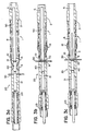
- Figures 2a-2c and 3a-3c show various steps in the driving of an insert.
- a piece of sheet metal 30 includes a hole 31 into which an insert is to be driven.
- a die 20 includes a locating pin 21 which is slidable through hole 22. Locating pin 21 is resiliently biased outwardly from the hole 22 by a helical compression spring 23.
- the sheet 30 is first roughly positioned in the assembly between the punch 1 and the die 20, with the hole 31 in the general vicinity of the axis of symmetry 5.
- the piece of sheet metal 30 is suspended in a vertical plane whereas the punch and the die are aligned along a horizontal axis.
- Vertical suspension of the sheet metal piece prevents problems connected with deformations caused by gravitational effects on a sheet that are apt to occur when a sheet is held horizontally, particularly when the sheet lacks stiffening bends.
- the axis of the hole 31 in the piece of sheet metal 30 is then aligned with the axis 5 of the punch using the locating pin 21, which is also aligned along the same axis.
- Fig. 2b the punch 1 is moved towards the sheet metal piece 30 until the blank holder 3 makes contact with the surface of the sheet 30.
- Fig. 2c the die 20 is moved towards the sheet metal piece 30 until the end of the die 20 makes contact with the sheet 30. During this movement, the locating pin 21 is inserted through the hole 31, thereby finely adjusts the alignment of the components. This step completes the gripping of the sheet between the punch and the die. At this time, the sheet is securely clamped between the distal end of the die 20 and the distal end of the blank holder 3.
- a thrust rod 50 is driven by an actuator (not shown) included in the press, to advance an insert 40 through the duct 6, to position the insert 40 in front of the thrust surface 9.
- the insert 40 is advanced to a position where it is restrained between the thrust rod 50 and the locating pin 21. At this position, the insert 40 is also laterally guided by the flat springs 16 of the blank holder 3.
- the thrust rod 50 continues to advance the insert, as shown in Fig. 3b, and drives a shank portion of the insert 40 through the hole 31.
- the punch 1 starts to advance towards the die 20.
- the advancement of the punch causes the heads 10 of the blades 8 to slide relative to the frusto-conical portion (internal surface) 14 of the blank holder 3.
- the heads 10 are pushed towards the axis of symmetry 5 by the frusto-conical portion 14 of the blank holder 3, as described above causing deformation of the blades 8.
- the inside diameter of the thrust surface 9 reduces until it becomes smaller than an outside diameter of a head 42 of the insert 40.
- the thrust surface 9 forms a bearing surface for the head 42.
- the punch 1 is further advanced to generate a driving force which is transmitted to the insert 40 by means of the blades 8 and the thrust surface 9.
- This driving force causes plastic deformation of the region of the sheet in the immediate vicinity of the hole 31, as the head of the insert is driven into the sheet.
- Fig. 3c shows the configuration of the device upon completion of the driving of the insert.
- the punch 1 is next brought back to its starting position, thereby allowing the spring 4 to return the blank holder 3 to the distal end of the punch 1, as the spring 4 returns to its least compressed position.
- the heads 10 of the blades 8 disengage from the frusto-conical surface 14, thereby allowing the blades 8 to return to their original, undeformed positions as shown in Fig. 1.
- the unrestricted, opening of the duct 6 is reestablished to permit the passage of a new insert therethrough.
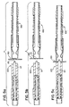
- Fig. 4 shows an alternative embodiment of the punch according to the present invention.
- the punch 100 includes a blank holder 103 which cooperates with a spring 104, in the same manner that the above-described blank holder 3 cooperates with spring 4.
- the punch 100 includes an insert-supply duct 106, which corresponds to the supply duct 6 of the first embodiment.
- a body 102 of the punch 100 includes a tubular member 122 in which blades 108 are formed, and a thrust member 123 mounted for sliding coaxially on the outer surface of the tubular member 122.
- the flexible blades 108 are formed by slits 113 made in the wall of the tubular member 122.
- the distal ends of the blades 108 include heads 110 which form the thrust surface 109, and which are fitted in an annular cavity 111 of the blank holder 103.
- the heads 110 further include abutment surfaces 117 and 118, which abut against opposite walls of the annular cavity 111.
- the heads further include inclined surfaces 119.
- the thrust member 123 is axially movable such that a distal end 126 thereof contacts the inclined surfaces 119 and slides with respect thereto.
- the walls of the thrust member are relatively unyielding and thus cause the blades 108 to bend towards an axis 105 of the device upon sliding movement of the distal end along the inclined surfaces 119.
- the blades 108 are bent sufficiently to release the heads 110 from the annular cavity 111.
- the distal end 126 slides along the inclined surfaces until it contacts the abutment surfaces 118 so as to transmit the thrust force thereof to the thrust surface 109.
- the spring 104 is located between an abutment element 217 of the blank holder 103 and an annular shoulder 112 formed on the thrust member 123.
- the thrust member 123 further includes an oblong groove 124 in which pins 125, fixed to the blank holder 103, are engaged.
- the blank holder 103 has windows 115 through which flat springs 116 extend. Springs are fixed to the abutment element 217 and function to laterally guide and restrain the inserts.
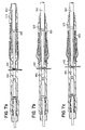
- the punch 100 is moved towards the sheet metal piece 130 until the blank holder makes contact with the surface of the sheet 130.
- the die 120 is moved towards the sheet metal piece 130 until the end of the die 120 makes contact with the sheet 130.
- the locating pin 121 is inserted through the hole 131, thereby finely adjusts the alignment of the components. This step completes the gripping of sheet between the punch and the die. At this time, the sheet is securely clamped between the distal end of the die 120 and the distal end of the blank holder.
- a thrust rod 150 is driven by an actuator (not shown) included in the press, to advance an insert 140 through the duct 106, to urge the shaft of the insert 140 through the hole 131, at the same time forcing the retraction of the locating pin 121 from the hole 131.
- the thrust member 123 is advanced, so that the distal end 126 slides against the inclined surfaces 119 of the heads 110 and causes bending of the blades 108 and the reduction in the inner diameter of the thrust surface 109.
- the thrust member 123 advances still further, the distal end 126 slides off the inclined surfaces 119 and comes into contact with the abutment surface 118 of the heads 110. Accordingly, the thrust member 123 entrains the tubular member 122, and drives the tubular member, through the contact between the distal end 126 and abutment surfaces 118, towards the head 142 of the insert 140.
- Figs. 7a and 7 b show that upon placement of the shank 140 of the insert through the hole 131, the tubular member 122 is advanced towards the die 120. The advancement of the tubular member 122 continues so that thrust surfaces 109 make contact with the head 142 of the insert as shown in Fig. 7b. Continued driving of the tubular member 122 and thus the thrust surfaces against the head 142 causes plastic deformation of the region of the sheet in the immediate vicinity of the hole 131, as the head 142 of the insert is driven into the sheet, and the movement of the tubular member is discontinued when abutment surfaces 117 make contact with the sheet 130.
- Fig. 7c shows the configuration of the device upon completion of the driving of the insert.
- the thrust member 123 is retracted.
- an actuator not shown, urges the tubular member 122 towards the distal end of the thrust member 123.
- the heads 110 of the blades 108 thus return to their original positions inside the cavity 111 of the blank holder 103 and the device is ready for a new cycle.
- the second embodiment of the punch is particularly advantageous owing to the fact that it avoids axial compression stresses on the blades 108.
Description
wherein:
Claims (12)
- A device for driving inserts (40,140) into pieces of sheet metal (30,130), comprising:a punch (1,100) having a body (2,102) extending along a longitudinal axis of symmetry (5,105); anda thrust surface (9,109) for applying a driving force to the inserts (40,140); characterized by a through hole (6,106) extending within said body (2,102), through said thrust surface (9,109) and through said punch (1,100) along said longitudinal axis (5,105) for moving the inserts (40,140) through said punch (1,100) and for placing the inserts (40,140) in front of said thrust surface (9,109) at a distal end of said punch (1,100), wherein said punch (1,100) further comprises flexible elements comprising blades (8,108) extending integrally from said body (2,102) along said axis of symmetry (5,105) towards said distal end of said punch (1,100), and each of said blades (8,108) comprises a head (10,110) at a distal end thereof, and said distal ends of said blades (8,108) form said thrust surface (9,109).
- A device according to claim 1, characterized by a blank holder (3,103) being coaxial with and coupled slidingly on an external surface of said body (2,102), and resilient means for urging said blank holder (3,103) toward said distal end of said body (2,102) such that said blank holder (3,103) forms an extension of said body (2,102).
- A device according to claim 2, characterized in that said blank holder (3) comprises an internal wall (14) for cooperating with said heads (10) of said blades (8) so that axial sliding of said blank holder (3) relative to said punch (1) causes said blades (8) to bend towards said axis of symmetry (5) of said punch (1).
- A device according to claim 3, characterized in that said internal wall (14) of said blank holder (3) is tapered towards said axis of symmetry (5) of said punch (1) in a direction from a proximal end of said punch (1) towards said distal end.
- A device according to at least one of the preceding claims 2 to 4, characterized in that each of said heads (10) of said blades (8) comprises an abutment element (11), and said blank holder (3) comprises an abutment element (17); and wherein said abutment elements (11) of said head (10) and said abutment element (17) of said blank holder (3) cooperate to prevent said blank holder (3) from sliding off said punch (1).
- A device according to claim 2, characterized in that said punch (100) further comprises a thrust member (123) being coaxial with said body (102), wherein said thrust member (123) is coupled with said body (102) for sliding on an external surface of said body (102), and wherein said blades have external surfaces for cooperating with said thrust member (123) so that sliding of said thrust member (123) relative to said body (102) causes said blades (108) to bend towards said axis of symmetry (105) of said punch (100).
- A device according to claim 6, characterized in that each of said heads (110) of said blades (108) comprises a portion having two abutment surfaces (117,118) which are fitted in a cavity (111) in said blank holder (103) to prevent said blank holder (103) from sliding axially relative to said punch (100).
- A device according to claim 7, characterized in that said sliding of said thrust member (123) relative to said body (102), to cause said blades (108) to bend towards said axis of symmetry (105), releases said portion of said heads (110) from said cavity (111) in said blank holder (103), to allow said blank holder (103) to slide axially relative to said punch (100).
- A device according to claim 7 or 8, characterized in that a distal end of said thrust member (123) comprises a free surface which contacts one of said two abutment surfaces (117,118) of each of said heads (110) of said blades (108) during driving of said thrust member (123) to transmit a thrust force from said thrust member (123) to said heads (110).
- A device according to at least one of the preceding claims 2 to 9, characterized in that said blank holder (3,103) comprises guide elements for guiding the inserts (40,140).
- A device according to claim 10, characterized in that said blank holder (3,103) further comprises through holes (15,115) along walls of said blank holder (3,103) and said guide elements comprise flat springs (16,116) which converge through said through holes (15,115) of said blank holder (3,103) toward said axis of symmetry (5,105) of said punch (1, 100) so as to guide the inserts (40,140) along said axis (5,105).
- A device according to at least one of the preceding claims 1 to 11, characterized by a rod (50,150) urging said inserts (40,140) through said through hole (6,106) in said punch (1, 100) to supply said inserts (40,140) for insertion.
Applications Claiming Priority (3)
| Application Number | Priority Date | Filing Date | Title |
|---|---|---|---|
| IT95TO000182A IT1278985B1 (en) | 1995-03-10 | 1995-03-10 | TOOL FOR PLANTING INSERTS IN SHEET METAL SHEETS |
| ITTO950182 | 1995-03-10 | ||
| PCT/US1996/002318 WO1996028277A1 (en) | 1995-03-10 | 1996-03-08 | A device for driving inserts into pieces of sheet metal |
Publications (3)
| Publication Number | Publication Date |
|---|---|
| EP0813461A1 EP0813461A1 (en) | 1997-12-29 |
| EP0813461A4 EP0813461A4 (en) | 2002-03-27 |
| EP0813461B1 true EP0813461B1 (en) | 2005-06-01 |
Family
ID=11413335
Family Applications (1)
| Application Number | Title | Priority Date | Filing Date |
|---|---|---|---|
| EP96911204A Expired - Lifetime EP0813461B1 (en) | 1995-03-10 | 1996-03-08 | A device for driving inserts into pieces of sheet metal |
Country Status (7)
| Country | Link |
|---|---|
| US (1) | US5788140A (en) |
| EP (1) | EP0813461B1 (en) |
| JP (1) | JPH11503368A (en) |
| AU (1) | AU5416396A (en) |
| DE (1) | DE69634798D1 (en) |
| IT (1) | IT1278985B1 (en) |
| WO (1) | WO1996028277A1 (en) |
Cited By (1)
| Publication number | Priority date | Publication date | Assignee | Title |
|---|---|---|---|---|
| CN102672093A (en) * | 2012-05-18 | 2012-09-19 | 上海拓璞数控科技有限公司 | Automatic rivet feeding mechanical device for full-automatic riveting machine and automatic rivet feeding method of device |
Families Citing this family (2)
| Publication number | Priority date | Publication date | Assignee | Title |
|---|---|---|---|---|
| DE102013010493A1 (en) * | 2013-06-25 | 2015-01-08 | Tox Pressotechnik Gmbh & Co. Kg | Device and method for the automated formation of a joint connection |
| CN112676526A (en) * | 2019-10-29 | 2021-04-20 | 许密芳 | Riveting machine and using method |
Family Cites Families (21)
| Publication number | Priority date | Publication date | Assignee | Title |
|---|---|---|---|---|
| US916026A (en) * | 1908-02-08 | 1909-03-23 | F H Smith Mfg Company | Rivet holding and driving chuck. |
| FR857160A (en) * | 1938-07-02 | 1940-08-29 | Improvements made to the means for axially guiding a part in translation, to include in particular the rivet dispensing devices | |
| DE750791C (en) * | 1938-12-24 | 1953-09-28 | Ernst Heinkel Flugzeugwerke G | Automatic riveting machine |
| US3042244A (en) * | 1958-06-12 | 1962-07-03 | Huck Mfg Co | Nose assembly for fastener applying tools |
| US3341559A (en) * | 1965-10-22 | 1967-09-12 | Squibb & Sons Inc | 17alpha-halo-16, 20-steroids of the pregnane and a-nor-pregnane series and methods for their preparation |
| GB1183049A (en) * | 1966-09-16 | 1970-03-04 | Avdel Ltd | Riveting Apparatus |
| US3465410A (en) * | 1967-03-08 | 1969-09-09 | Penn Eng & Mfg Corp | Automated machine or press for assembling a fastener to a workpiece |
| US3647129A (en) * | 1968-10-21 | 1972-03-07 | Trw Inc | Stud feeding system for welding tools |
| GB1328498A (en) * | 1969-09-26 | 1973-08-30 | Avdel Ltd | Collar carrying device for use with lockbolt swaging apparatus |
| US3695499A (en) * | 1971-06-09 | 1972-10-03 | Taylor Industries | Fastener installation |
| SE380606B (en) * | 1973-11-30 | 1975-11-10 | Gebelius Sven Runo Vilhelm | PROCEDURE TO CONNECT A TUB-SLEEVE SLEEVE TO A PLATE WALL AND A DEVICE FOR IMPLEMENTING THE KIT |
| US4059980A (en) * | 1975-11-17 | 1977-11-29 | Olympic Fastening Systems, Inc. | Method and means for installing blind fasteners |
| US4052788A (en) * | 1976-07-06 | 1977-10-11 | Cutler-Hammer, Inc. | Tool for removing a snap-in bushing from a mounting panel hole |
| US4596349A (en) * | 1985-05-02 | 1986-06-24 | William Prym-Werke Kg | Machine for applying articles of hardware to textile materials and the like |
| US4628722A (en) * | 1986-02-14 | 1986-12-16 | Usm Corporation | Setting tool for rivet with pull-headed mandrel |
| US4706868A (en) * | 1986-02-24 | 1987-11-17 | Trw Inc. | Panel fastener assembly system |
| US4709841A (en) * | 1986-06-09 | 1987-12-01 | Phillips Plastics Corporation | Tool for installing expandable fastener |
| GB2244230A (en) * | 1990-05-23 | 1991-11-27 | Avdel Systems Ltd | Apparatus for presenting blind rivets |
| GB2248573A (en) * | 1990-10-05 | 1992-04-15 | Avdel Systems Ltd | Nosepiece assembly |
| GB9218463D0 (en) * | 1992-08-29 | 1992-10-14 | Emhart Inc | Rivet setting tool |
| US5341559A (en) * | 1993-04-13 | 1994-08-30 | Fatigue Technology, Inc. | Method and apparatus for securing a tubular bushing in a circular opening |
-
1995
- 1995-03-10 IT IT95TO000182A patent/IT1278985B1/en active IP Right Grant
-
1996
- 1996-03-08 US US08/613,142 patent/US5788140A/en not_active Expired - Fee Related
- 1996-03-08 EP EP96911204A patent/EP0813461B1/en not_active Expired - Lifetime
- 1996-03-08 AU AU54163/96A patent/AU5416396A/en not_active Abandoned
- 1996-03-08 DE DE69634798T patent/DE69634798D1/en not_active Expired - Lifetime
- 1996-03-08 JP JP8527610A patent/JPH11503368A/en active Pending
- 1996-03-08 WO PCT/US1996/002318 patent/WO1996028277A1/en active IP Right Grant
Cited By (1)
| Publication number | Priority date | Publication date | Assignee | Title |
|---|---|---|---|---|
| CN102672093A (en) * | 2012-05-18 | 2012-09-19 | 上海拓璞数控科技有限公司 | Automatic rivet feeding mechanical device for full-automatic riveting machine and automatic rivet feeding method of device |
Also Published As
| Publication number | Publication date |
|---|---|
| IT1278985B1 (en) | 1997-12-02 |
| ITTO950182A1 (en) | 1996-09-10 |
| EP0813461A1 (en) | 1997-12-29 |
| DE69634798D1 (en) | 2005-07-07 |
| ITTO950182A0 (en) | 1995-03-10 |
| EP0813461A4 (en) | 2002-03-27 |
| AU5416396A (en) | 1996-10-02 |
| WO1996028277A1 (en) | 1996-09-19 |
| US5788140A (en) | 1998-08-04 |
| JPH11503368A (en) | 1999-03-26 |
Similar Documents
| Publication | Publication Date | Title |
|---|---|---|
| CA1283635C (en) | Apparatus for installing fasteners | |
| EP0581385B1 (en) | Split sleeve cold expansion | |
| US5779127A (en) | Fastening machines | |
| US3934325A (en) | Fastening method, apparatus and article | |
| US3906776A (en) | Self-drilling blind riveting tool | |
| JPH0675741B2 (en) | Head fastener feeder and riveter with feeder | |
| GB2232110A (en) | Fastener installation apparatus | |
| EP3597357A1 (en) | Blind rivet nut setting device | |
| US20040168294A1 (en) | Riveting tool and method of its use | |
| DE102017203943A1 (en) | Setting unit and method for setting a connecting element on a workpiece | |
| US5400942A (en) | Automatic fastener feed apparatus and method | |
| JP2963799B2 (en) | Nosepiece device for blind rivet setting tool | |
| EP0813461B1 (en) | A device for driving inserts into pieces of sheet metal | |
| EP0512806A1 (en) | Offset nose assembly with pin releasing assembly for fastener installation tools | |
| ES2903447T3 (en) | Device as well as method for placing a connecting element on a workpiece | |
| GB1565082A (en) | Blind-reveting tools | |
| EP1980342B1 (en) | Head for riveting machine with jaw release assembly | |
| JP3794921B2 (en) | Riveting machine | |
| WO1989003167A1 (en) | Pick up head | |
| US4693109A (en) | Self-aligning tool assembly for die shaping workpieces | |
| US5657536A (en) | Apparatus for attaching self-piercing nuts to a panel | |
| US4708039A (en) | Bar feeding apparatus | |
| US5519927A (en) | Rivet setting tool | |
| EP0246206B1 (en) | Nail-feeding device | |
| EP0641629A1 (en) | Fastener feeder apparatus |
Legal Events
| Date | Code | Title | Description |
|---|---|---|---|
| PUAI | Public reference made under article 153(3) epc to a published international application that has entered the european phase |
Free format text: ORIGINAL CODE: 0009012 |
|
| 17P | Request for examination filed |
Effective date: 19970902 |
|
| AK | Designated contracting states |
Kind code of ref document: A1 Designated state(s): BE CH DE ES FI FR GB LI SE |
|
| A4 | Supplementary search report drawn up and despatched |
Effective date: 20020208 |
|
| AK | Designated contracting states |
Kind code of ref document: A4 Designated state(s): BE CH DE ES FI FR GB LI SE |
|
| RIC1 | Information provided on ipc code assigned before grant |
Free format text: 7B 23Q 3/00 A, 7B 21J 15/02 B, 7B 21J 15/32 B |
|
| 17Q | First examination report despatched |
Effective date: 20030714 |
|
| GRAP | Despatch of communication of intention to grant a patent |
Free format text: ORIGINAL CODE: EPIDOSNIGR1 |
|
| GRAS | Grant fee paid |
Free format text: ORIGINAL CODE: EPIDOSNIGR3 |
|
| GRAA | (expected) grant |
Free format text: ORIGINAL CODE: 0009210 |
|
| AK | Designated contracting states |
Kind code of ref document: B1 Designated state(s): BE CH DE ES FI FR GB LI SE |
|
| PG25 | Lapsed in a contracting state [announced via postgrant information from national office to epo] |
Ref country code: LI Free format text: LAPSE BECAUSE OF FAILURE TO SUBMIT A TRANSLATION OF THE DESCRIPTION OR TO PAY THE FEE WITHIN THE PRESCRIBED TIME-LIMIT Effective date: 20050601 Ref country code: FI Free format text: LAPSE BECAUSE OF FAILURE TO SUBMIT A TRANSLATION OF THE DESCRIPTION OR TO PAY THE FEE WITHIN THE PRESCRIBED TIME-LIMIT Effective date: 20050601 Ref country code: CH Free format text: LAPSE BECAUSE OF FAILURE TO SUBMIT A TRANSLATION OF THE DESCRIPTION OR TO PAY THE FEE WITHIN THE PRESCRIBED TIME-LIMIT Effective date: 20050601 Ref country code: BE Free format text: LAPSE BECAUSE OF FAILURE TO SUBMIT A TRANSLATION OF THE DESCRIPTION OR TO PAY THE FEE WITHIN THE PRESCRIBED TIME-LIMIT Effective date: 20050601 |
|
| REG | Reference to a national code |
Ref country code: GB Ref legal event code: FG4D |
|
| REG | Reference to a national code |
Ref country code: CH Ref legal event code: EP |
|
| REF | Corresponds to: |
Ref document number: 69634798 Country of ref document: DE Date of ref document: 20050707 Kind code of ref document: P |
|
| PG25 | Lapsed in a contracting state [announced via postgrant information from national office to epo] |
Ref country code: SE Free format text: LAPSE BECAUSE OF FAILURE TO SUBMIT A TRANSLATION OF THE DESCRIPTION OR TO PAY THE FEE WITHIN THE PRESCRIBED TIME-LIMIT Effective date: 20050901 |
|
| PG25 | Lapsed in a contracting state [announced via postgrant information from national office to epo] |
Ref country code: DE Free format text: LAPSE BECAUSE OF FAILURE TO SUBMIT A TRANSLATION OF THE DESCRIPTION OR TO PAY THE FEE WITHIN THE PRESCRIBED TIME-LIMIT Effective date: 20050902 |
|
| REG | Reference to a national code |
Ref country code: CH Ref legal event code: PL |
|
| PG25 | Lapsed in a contracting state [announced via postgrant information from national office to epo] |
Ref country code: GB Free format text: LAPSE BECAUSE OF NON-PAYMENT OF DUE FEES Effective date: 20060308 |
|
| PLBE | No opposition filed within time limit |
Free format text: ORIGINAL CODE: 0009261 |
|
| STAA | Information on the status of an ep patent application or granted ep patent |
Free format text: STATUS: NO OPPOSITION FILED WITHIN TIME LIMIT |
|
| ET | Fr: translation filed | ||
| 26N | No opposition filed |
Effective date: 20060302 |
|
| GBPC | Gb: european patent ceased through non-payment of renewal fee |
Effective date: 20060308 |
|
| PG25 | Lapsed in a contracting state [announced via postgrant information from national office to epo] |
Ref country code: ES Free format text: LAPSE BECAUSE OF NON-PAYMENT OF DUE FEES Effective date: 20060331 |
|
| REG | Reference to a national code |
Ref country code: FR Ref legal event code: PLFP Year of fee payment: 20 |
|
| PGFP | Annual fee paid to national office [announced via postgrant information from national office to epo] |
Ref country code: FR Payment date: 20150319 Year of fee payment: 20 |