EP0813044A2 - Multi-frequency ultrasonic liquid level gauging system - Google Patents
Multi-frequency ultrasonic liquid level gauging system Download PDFInfo
- Publication number
- EP0813044A2 EP0813044A2 EP97304169A EP97304169A EP0813044A2 EP 0813044 A2 EP0813044 A2 EP 0813044A2 EP 97304169 A EP97304169 A EP 97304169A EP 97304169 A EP97304169 A EP 97304169A EP 0813044 A2 EP0813044 A2 EP 0813044A2
- Authority
- EP
- European Patent Office
- Prior art keywords
- liquid
- transmitting
- ultrasonic
- signal
- signals
- Prior art date
- Legal status (The legal status is an assumption and is not a legal conclusion. Google has not performed a legal analysis and makes no representation as to the accuracy of the status listed.)
- Withdrawn
Links
Images


Classifications
-
- G—PHYSICS
- G01—MEASURING; TESTING
- G01F—MEASURING VOLUME, VOLUME FLOW, MASS FLOW OR LIQUID LEVEL; METERING BY VOLUME
- G01F23/00—Indicating or measuring liquid level or level of fluent solid material, e.g. indicating in terms of volume or indicating by means of an alarm
- G01F23/22—Indicating or measuring liquid level or level of fluent solid material, e.g. indicating in terms of volume or indicating by means of an alarm by measuring physical variables, other than linear dimensions, pressure or weight, dependent on the level to be measured, e.g. by difference of heat transfer of steam or water
- G01F23/28—Indicating or measuring liquid level or level of fluent solid material, e.g. indicating in terms of volume or indicating by means of an alarm by measuring physical variables, other than linear dimensions, pressure or weight, dependent on the level to be measured, e.g. by difference of heat transfer of steam or water by measuring the variations of parameters of electromagnetic or acoustic waves applied directly to the liquid or fluent solid material
- G01F23/296—Acoustic waves
- G01F23/2962—Measuring transit time of reflected waves
-
- G—PHYSICS
- G01—MEASURING; TESTING
- G01F—MEASURING VOLUME, VOLUME FLOW, MASS FLOW OR LIQUID LEVEL; METERING BY VOLUME
- G01F22/00—Methods or apparatus for measuring volume of fluids or fluent solid material, not otherwise provided for
Definitions
- the present invention relates generally to systems for the detection of fluid levels, and more particularly to a multi-frequency ultrasonic liquid gauging system for detecting liquid levels in storage tanks.
- a capacitance probe is used to measure the liquid level in storage tanks.
- the capacitance probe relies upon the dielectric difference between the liquid and air in the storage tank.
- the capacitance probe is mounted vertically in the storage tank and the liquid level (and consequently the quantity of liquid in the tank) is periodically measured by a processor connected to the capacitance probe.
- Such capacitance systems commonly employ multiple probes, wired in parallel, particularly in large or irregularly-shaped tanks. It can be difficult to determine the contribution of each probe to the overall liquid level measurement.
- One solution is to individually wire each probe to its associated electronics. However, this can increase the cost and weight of the system.
- FIG. 1 of the accompanying drawings is a diagram of a tank 10 and a sensing portion 12 of a known multiple-probe ultrasonic level gauge system.
- the sensing portion 12 includes a number of probes 14a-14d oriented perpendicular with respect to the bottom surface 18 of tank.
- Each probe 14a-14d includes a stillwell 16a-16d and an ultrasonic transducer 20a-20d, respectively, located at the bottom of each stillwell.
- a remote processing system (not shown) separately excites and receives signals from each transducer 20a-20d over a dedicated wire pair 22a-22d.
- a drive pulse is transmitted to each transducer 20a-20d over an associated wire pair 22a-22d causing each transducer to generate an ultrasonic signal which propagates from the transducer 20 toward the surface 24 of liquid 26.
- the ultrasonic signal reflects off of the interface of the liquid 26 and air 28 which is the surface 24 of the liquid and propagates back to the transducer 20. Knowing the speed of sound through the particular liquid 26 and the measured time for the ultrasonic signal to propagate from a transducer 20 to the surface 24 of liquid 26 and back, the depth of the liquid in storage tank 10 can be calculated.
- an ultrasonic liquid level gauging system for determining a liquid level in a storage apparatus, characterized by a plurality of ultrasonic transmitting and receiving means, each transmitting and receiving means introducing a distinct ultrasonic signal into the storage apparatus and receiving a reflected signal therefrom;
- the ultrasonic liquid level gauging system particularly includes a storage apparatus, such as a tank, for storing a quantity of liquid, such as fuel, and a plurality of probes, each of which includes a stillwell with an ultrasonic transduver located at the bottom of the stillwell.
- a storage apparatus such as a tank
- Each of the ultrasonic transducers operates at a different frequency, and is connected to a remote processing system over shared wiring. Such a connection can reduce the cost and weight of wiring overhead in the system.
- a method of measuring the level of liquid in a storage apparatus characterized by the steps of:
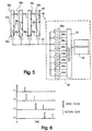
- Fig. 6 is a timing graph illustrating the amplitude response of the transmitted and reflected signal of the transducers in the liquid level gauging system of Fig. 5.
- the liquid level gauging system 30 includes a number of probes 38a-38d, each of which includes a transducer 36a-36d, respectively, situated for monitoring the level of liquid at various locations, for example with stillwells 37a-37d.
- a "stillwell” is recognized by those skilled in the art as a narrow, constant-diameter tube extending from the bottom of the tank to the top of the tank, with openings near or at the bottom for allowing liquid to enter and equalize within the stillwell.
- the stillwell provides a quiet, sheltered area for the accurate measurement of the level of the liquid.
- the transducers 36a-36d preferably operate and communicate with a remote processing system 40 at distinct signal frequencies over one or more shared wiring pairs 42.
- the remote processing system 40 drives each of the transducers 36a-36d over the shared wiring pair 42 coupled to each transducer.
- each transducer propagates a distinct ultrasonic signal through the liquid 32 in the tank 34.
- the ultrasonic signals reflected from the liquid/air interface 44 are sensed by the corresponding transducers which communicate the signals to the remote processing system 40 over a wiring pair shared by at least two transducers.
- the remote processing system calculates the liquid level 44 in the tank.
- transducers of the gauging system can be coupled to the remote processing system over a shared wiring pair, i.e., in parallel, thereby permitting a lightweight and inexpensive liquid level gauging solution while maintaining a unique frequency signature for each transducer. Consequently, independent data on liquid levels can be obtained throughout the storage tank.
- transducers 36a-36d are located within tank 34, alternative embodiments may utilize transducers located external to the tank, such as operational through ports in the tank.
- each transducer 36-36d is shown coupled in parallel to a single shared wiring pair 42 via wiring pairs 46a-46d, in some embodiments, more than a single shared wiring pair 42 may be employed.
- FIG. 3 schematically illustrates the liquid level gauge 30 with the remote processing system 40 shown in detail.
- the remote processing system 40 includes a driver 48 and filter network 50 coupled to a multiplexer 52 which in turn is coupled to a processor 54.
- the filter network 50 includes a plurality of filters 56a-56d corresponding to the transducers 36a-36d, respectively, operating at frequencies f1-f4, respectively.
- Driver 48 via multiplexer 52 and processor 54, drives transducers 36a-36d located within stillwells 37a-37d.
- Processor 54 operates in conjunction with multiplexer 52 such that it can select either driver 48 to excite and therefore transmit ultrasonic signals in each of transducers 36a-36d, or receive data that has been received from the transducers through filters 56a-56d.
- the remote processing system 40 employs processor 54 in conjunction with multiplexer 52, driver 48, and filters 56a-56d to transmit and receive information via a shared path 42 to transducers 36a-36d.
- the shared path is a twisted wire pair.
- the shared path may consist of a bus or any other type conductor that is operable to transmit electrical signals.
- Figure 3 illustrates an exemplary embodiment having four transducers and filters, the invention could be utilized with any number of transducers and filters.
- the operation of remote processing system 40 in conjunction with transducers 36a-36d of probes 38a-38d may be better understood in conjunction with Figure 4.
- FIG. 4 illustrates a timing diagram for each signal, illustrated as signals fl-f4, received from the transducers 36a-36d having an amplitude response with respect to time.
- Processor 54 in conjunction with multiplexer 52, selects driver 48 to excite transducers 36a-36d with a square wave pulse.
- transducers 36a-36d may consist of crystals, each having a unique resonant frequency. Therefore, when driver 48 excites the plurality of transducers with a square wave pulse (which contains all the frequencies in the frequency domain), each transducer emits an ultrasonic signal having a unique frequency wherein the frequency is a function of the resonant frequency of that transducer.
- transducer 36a in stillwell 37a may have a resonant frequency of 1 Mhz wherein the transducer 36b in stillwell 37b may have a resonant frequency of 1.1 Mhz.
- Transducers 36c and 36d likewise have their own unique resonant frequencies.
- the transducer having a resonant frequency of 1 Mhz will therefore emit an ultrasonic signal having a frequency of 1 Mhz.
- the ultrasonic signal propagates through the liquid 32 within tank 34 and reaches the interface 44 between the liquid and the air.
- the ultrasonic signal reflects off the interface 44 and is subsequently received by transducer 36a.
- each transducer 36a-36d will receive a reflected ultrasonic signal having a unique frequency associated with the crystal in that transducer.
- Each reflected signal is then communicated back to remote processing system 40 via shared path 42.
- the plurality of filters 56a-56d subsequently filter the reflected signals.
- filter 56a associated with transducer 36a of probe 38a. Since the resonant frequency of the transducer 36a is 1 Mhz, the filter 56a may preferably consist of a band-pass filter centered around the frequency 1 Mhz. Filter 56a will distinguish that reflected signal from the other reflected signals in the parallel configuration. Filters 56b-56d provide similar functionality. In alternative embodiments, filters 56a-56d may consist of any type of filtration arrangement that effectively distinguishes each signal from the plurality of reflected signals. Multiplexer 52 then selects, according to commands from processor 54, the information to be passed to processor 54.
- the liquid level depth will be substantially uniform throughout the tank. Therefore, the amplitude response will be similar to that illustrated in Figure 4. Because the depth of the liquid is proportional to the propagation time through the liquid, deviations in the amplitude/time response may be attributed to a different liquid level depth, an irregularity in the storage tank or thermal variances throughout the liquid. Many storage tanks, however, have irregular shapes. For example, in aviation applications, a fuel storage tank generally assumes the shape of the wing of its respective aircraft. Processor 54 can map depth calculations of each individual transducer since each transducer has its own unique frequency signature. Therefore, although the plurality of reflected signals may substantially overlap one another in the time domain, they are distinguishable in the frequency domain. Filters 56a-56d allow for the filtration of each signal to provide processor 54 a clear signal response for subsequent calculation of the liquid level.
- FIG. 5 illustrates an alternative embodiment of the present invention with a liquid level gauge system 60.
- Liquid level gauging system 60 is similar to system 20 of Figure 3 in that it includes a plurality of transducers 36a-36d located in stillwells 37a-37d of probes 38a-38d.
- transducers 36a-36d are connected in parallel along wiring pair 42.
- a remote processing system 62 contains multiplexer 52, processor 54 and a plurality of filters 56a-56d as in the first embodiment, and further includes a plurality of drivers 64a-64d.
- the plurality of drivers 64a-64d individually excite or drive each transducer.
- driver 64a drives transducer 36a located within stillwell 37a, while each of the remaining drivers 64b-64d drive their respective transducers 36b-36d.
- Gauging system 60 like gauging system 30 of Figure 3, embodies the advantages of parallel systems with the advantage of maintaining the unique signature of each transducer.
- the operation of gauging system 60 may best be understood in conjunction with Figure 6.
- Figure 6 illustrates a graph showing an amplitude response for each reflected signal from the plurality of transducers with respect to time. Although Figure 6 illustrates the excitation and echo (reflected signal) wave forms occurring at different times, this is not required by gauging system 60. Rather, instead of drivers 64a-64d emitting square wave pulses, as did driver 48 of Figure 3, drivers 64a-64d can each emit sinusoidal signals having a particular frequency that matches a unique resonant frequency of a particular transducer.
- FIG. 6 illustrates the various drive pulses as square wave for ease of illustration.
- Each drive pulse is actually sinusoidal and occupies a unique frequency.
- driver 64a in this exemplary embodiment
- Filters 56a-56d receive each reflected signal and distinguish the signal through bandpass filtration. Although bandpass filtration is particularly disclosed in this particular embodiment, other forms of filtration may be utilized and would constitute alternative embodiments of the invention.
- processor 54 receives the filtered signals and calculates liquid levels proximate to each respective transducer.
- Figure 6 illustrates, as one example, each transducer being driven sequentially with respect to time.
- filtration would not be required to differentiate various signals on the single conductive path.
- the invention contemplates such an alternative embodiment which eliminates such filtration.
- Gauging system 60 of Figure 5 need not operate sequentially but could drive transducers 36a-36d simultaneously. In such an example, each transducer would still be individually excited and filters 56a-56d would distinguish the unique frequency responses that may be indistinguishable in the time domain.
- a procedure for calibration of the liquid level gauging system may be incorporated with gauging system 30 of Figure 3 or gauging system 60 of Figure 5.
- the purpose of executing a calibration procedure is to correct for variations in the speed of sound in fuel for the calculation methodology executed by processor 54.
- the method of calibration may be a function of the application or shape of the storage tank.
- a simple storage tank such as an underground fuel tank, for example, a single calibration pin may be used for the entire tank.
- a multiple pin calibration technique can be used. For example, as illustrated in Figure 5, multiple calibration pins 68 can be placed vertically along the sidewall of each stillwell.
- multiple calibration pins could be placed vertically along a sidewall of the storage tank).
- the distance between each transducer and their respective vertically-located calibration pins is a known distance.
- Ultrasonic signals are emitted from the transducers and reflect upon each calibration pin in its respective stillwell.
- Processor 54 then collects the data and compares its measured distances between the transducers and their respective calibration pins with the known distances. The comparison is then used either to validate or modify the calculation methodology of processor 54.
- the liquid level in a storage tank can be determined when the temperature throughout the liquid is not uniform. It is important to note that since the speed of sound through a liquid is a function of the temperature of the liquid, utilizing multiple calibration pins vertically along each stillwell allows processor 54 to construct an approximate vertical thermal gradient of the liquid in the tank by identifying the effect of temperature throughout the liquid. Processor 54 may then use the thermal effect information in calculating the liquid level depth in the storage tank. Construction of a thermal gradient by processor 54 is advantageous in aviation-type applications. Fuel storage tanks are often located in the wing of an aircraft. As an aircraft is in flight, the temperatures at high altitudes may vary significantly.
- Gauging system 30 of Figure 3 and gauging system 60 of Figure 5 each advantageously simplify the wiring of multi-sensor or multi-transducer gauging systems by allowing transducers to be coupled together in parallel, thereby reducing multiple-twisted wire pairs between the transducers and associated electronics to a single-twisted wire pair.
- This reduction in wiring overhead substantially reduces the space and weight of the liquid level gauging system. Additionally, the reduction in wiring overhead results in increased system reliability by decreasing the number of pieces of needed equipment.
- one could utilize a second-wire pair which could be selectively coupled to remote processing systems 40 and 62 of Figures 3 and 5, to enhance fault survival of the liquid level gauging system.
- Gauging system 30 of Figure 3 and gauging system 60 of Figure 5 also advantageously provide for individual identification of each transducer through use of a unique frequency signature for each transducer.
- Processor 54 can therefore identify each transducer when coupled together in parallel without the wiring overhead required by prior art systems where each probe was individually coupled to the electronics.
- Processor 54 may map the liquid level throughout the tank while simultaneously having the transducers coupled together in parallel. Further, use of calibration pins allows processor 54 to accurately gauge the actual propagation rate of sound through the liquid, thereby characterizing the liquid and identifying the thermal effects on the liquid. Such characterization and identification provide accuracy in liquid level calculations.
Abstract
Description
- The present invention relates generally to systems for the detection of fluid levels, and more particularly to a multi-frequency ultrasonic liquid gauging system for detecting liquid levels in storage tanks.
- Various systems for detecting the liquid level in a storage tank have been utilized in the past. In one measuring system a capacitance probe is used to measure the liquid level in storage tanks. The capacitance probe relies upon the dielectric difference between the liquid and air in the storage tank. The capacitance probe is mounted vertically in the storage tank and the liquid level (and consequently the quantity of liquid in the tank) is periodically measured by a processor connected to the capacitance probe. Such capacitance systems commonly employ multiple probes, wired in parallel, particularly in large or irregularly-shaped tanks. It can be difficult to determine the contribution of each probe to the overall liquid level measurement. One solution is to individually wire each probe to its associated electronics. However, this can increase the cost and weight of the system.
- Another measuring system works upon the principle of transmitting an ultrasonic signal from a signal source through the liquid. For example, Figure 1 of the accompanying drawings is a diagram of a
tank 10 and asensing portion 12 of a known multiple-probe ultrasonic level gauge system. Thesensing portion 12 includes a number ofprobes 14a-14d oriented perpendicular with respect to thebottom surface 18 of tank. Eachprobe 14a-14d includes astillwell 16a-16d and anultrasonic transducer 20a-20d, respectively, located at the bottom of each stillwell. A remote processing system (not shown) separately excites and receives signals from eachtransducer 20a-20d over adedicated wire pair 22a-22d. To sense thelevel 24 ofliquid 26 in the tank 10 a drive pulse is transmitted to eachtransducer 20a-20d over an associatedwire pair 22a-22d causing each transducer to generate an ultrasonic signal which propagates from the transducer 20 toward thesurface 24 ofliquid 26. The ultrasonic signal reflects off of the interface of theliquid 26 andair 28 which is thesurface 24 of the liquid and propagates back to the transducer 20. Knowing the speed of sound through theparticular liquid 26 and the measured time for the ultrasonic signal to propagate from a transducer 20 to thesurface 24 ofliquid 26 and back, the depth of the liquid instorage tank 10 can be calculated. - While such a system is able to differentiate signals from the separate transducers by virtue of the dedicated wire pairs, the overhead of routing the individual wiring from each transducer to the remote processing system can again add to the cost and weight of the liquid level measuring system. In aviation-type fuel tanks the weight of a liquid level gauging system can be an important design constraint.
- In view of the above mentioned shortcomings of conventional liquid level measuring systems, it is believed that there is a demand in the market for an ultrasonic system which is lightweight and inexpensive, and which permits mapping of the liquid level in the tank.
- According to one aspect of the present invention there is provided an ultrasonic liquid level gauging system for determining a liquid level in a storage apparatus, characterized by a plurality of ultrasonic transmitting and receiving means, each transmitting and receiving means introducing a distinct ultrasonic signal into the storage apparatus and receiving a reflected signal therefrom;
- circuit means for driving the transmitting and receiving means and receiving reflected signals from the transmitting and receiving means;
- and processor means in communication with the circuit which calculates the liquid level at each of the locations of the transmitting and receiving means based on the reflected signal received by the circuit from each transmitting and receiving means.
- The ultrasonic liquid level gauging system particularly includes a storage apparatus, such as a tank, for storing a quantity of liquid, such as fuel, and a plurality of probes, each of which includes a stillwell with an ultrasonic transduver located at the bottom of the stillwell. Each of the ultrasonic transducers operates at a different frequency, and is connected to a remote processing system over shared wiring. Such a connection can reduce the cost and weight of wiring overhead in the system.
- According to another aspect of the invention there is provided a method of measuring the level of liquid in a storage apparatus, characterized by the steps of:
- transmitting a drive signal to a plurality of ultrasonic signal sources, wherein each of the plurality of sources is operable to transmit ultrasonic signals having unique frequencies;
- transmitting a plurality of ultrasonic signals from the sources through the liquid, wherein each signal may be reflected in the liquid, thereby creating a plurality of reflected signals, wherein each reflected signal has a unique frequency corresponding to its respective source;
- communicating the reflected signals to a processor;
- distinguishing each of the plurality of reflected signals; and
- calculating the depth of the liquid level at various storage apparatus locations from each of the distinguished reflected signals, wherein the depth of the liquid is a function of the propagation time of each signal through the liquid.
- The invention is diagrammatically illustrated by way of example in the accompanying drawings, in which: -
- Fig. 1 is a cross-sectional diagram illustrating a tank and a prior art ultrasonic liquid level gauging system;
- Fig. 2 is a cross-sectional diagram illustrating a tank with a ultrasonic liquid level gauging system constructed according to a first embodiment of the present invention;
- Fig. 3 is a cross-sectional diagram detailing remote processing apparatus of the liquid level gauging system of Fig. 2;
- Fig. 4 is a timing graph illustrating the amplitude response of the transmitted and reflected signal of the transducers in the liquid level gauging system of Fig. 2;
- Fig. 5 is a cross-sectional diagram detailing the remote processing apparatus of an ultrasonic liquid gauging system constructed according to a second embodiment of the present invention; and
- Fig. 6 is a timing graph illustrating the amplitude response of the transmitted and reflected signal of the transducers in the liquid level gauging system of Fig. 5.
- With reference to Figure 2, there is shown a liquid
level gauging system 30 in accordance with a first embodiment of the present invention for gauging the level of aliquid 32, such as fuel, in astorage tank 34. The liquidlevel gauging system 30 includes a number ofprobes 38a-38d, each of which includes atransducer 36a-36d, respectively, situated for monitoring the level of liquid at various locations, for example withstillwells 37a-37d. A "stillwell" is recognized by those skilled in the art as a narrow, constant-diameter tube extending from the bottom of the tank to the top of the tank, with openings near or at the bottom for allowing liquid to enter and equalize within the stillwell. The stillwell provides a quiet, sheltered area for the accurate measurement of the level of the liquid. Thetransducers 36a-36d preferably operate and communicate with aremote processing system 40 at distinct signal frequencies over one or more sharedwiring pairs 42. - In operation, the
remote processing system 40 drives each of thetransducers 36a-36d over the sharedwiring pair 42 coupled to each transducer. In response to the drive signal from theremote processing system 40, each transducer propagates a distinct ultrasonic signal through theliquid 32 in thetank 34. The ultrasonic signals reflected from the liquid/air interface 44 are sensed by the corresponding transducers which communicate the signals to theremote processing system 40 over a wiring pair shared by at least two transducers. Based on the time required for the signal to propagate through theliquid 32 in thetank 34, the remote processing system calculates theliquid level 44 in the tank. By employing transducers operating at different frequencies, multiple transducers of the gauging system can be coupled to the remote processing system over a shared wiring pair, i.e., in parallel, thereby permitting a lightweight and inexpensive liquid level gauging solution while maintaining a unique frequency signature for each transducer. Consequently, independent data on liquid levels can be obtained throughout the storage tank. - It is noted that although in this
particular embodiment transducers 36a-36d are located withintank 34, alternative embodiments may utilize transducers located external to the tank, such as operational through ports in the tank. Moreover, while each transducer 36-36d is shown coupled in parallel to a single sharedwiring pair 42 viawiring pairs 46a-46d, in some embodiments, more than a single sharedwiring pair 42 may be employed. - Figure 3 schematically illustrates the
liquid level gauge 30 with theremote processing system 40 shown in detail. Theremote processing system 40 includes a driver 48 andfilter network 50 coupled to amultiplexer 52 which in turn is coupled to aprocessor 54. Thefilter network 50 includes a plurality offilters 56a-56d corresponding to thetransducers 36a-36d, respectively, operating at frequencies f1-f4, respectively. Driver 48, viamultiplexer 52 andprocessor 54, drivestransducers 36a-36d located withinstillwells 37a-37d.Processor 54 operates in conjunction withmultiplexer 52 such that it can select either driver 48 to excite and therefore transmit ultrasonic signals in each oftransducers 36a-36d, or receive data that has been received from the transducers throughfilters 56a-56d. Theremote processing system 40 employsprocessor 54 in conjunction withmultiplexer 52, driver 48, and filters 56a-56d to transmit and receive information via a sharedpath 42 totransducers 36a-36d. In a preferred embodiment the shared path is a twisted wire pair. In alternative embodiments, however, the shared path may consist of a bus or any other type conductor that is operable to transmit electrical signals. Although Figure 3 illustrates an exemplary embodiment having four transducers and filters, the invention could be utilized with any number of transducers and filters. The operation ofremote processing system 40 in conjunction withtransducers 36a-36d ofprobes 38a-38d may be better understood in conjunction with Figure 4. - Figure 4 illustrates a timing diagram for each signal, illustrated as signals fl-f4, received from the
transducers 36a-36d having an amplitude response with respect to time.Processor 54, in conjunction withmultiplexer 52, selects driver 48 to excitetransducers 36a-36d with a square wave pulse. In one embodiment,transducers 36a-36d may consist of crystals, each having a unique resonant frequency. Therefore, when driver 48 excites the plurality of transducers with a square wave pulse (which contains all the frequencies in the frequency domain), each transducer emits an ultrasonic signal having a unique frequency wherein the frequency is a function of the resonant frequency of that transducer. - For example,
transducer 36a instillwell 37a may have a resonant frequency of 1 Mhz wherein thetransducer 36b instillwell 37b may have a resonant frequency of 1.1 Mhz.Transducers tank 34 and reaches theinterface 44 between the liquid and the air. The ultrasonic signal reflects off theinterface 44 and is subsequently received bytransducer 36a. (Since a single square wave drive signal from driver 48 will excite an ultrasonic signal in eachtransducer 36a-36d, each transducer will receive a reflected ultrasonic signal having a unique frequency associated with the crystal in that transducer.) Each reflected signal is then communicated back toremote processing system 40 via sharedpath 42. The plurality offilters 56a-56d subsequently filter the reflected signals. - Consider, as an example,
filter 56a associated withtransducer 36a ofprobe 38a. Since the resonant frequency of thetransducer 36a is 1 Mhz, thefilter 56a may preferably consist of a band-pass filter centered around the frequency 1 Mhz.Filter 56a will distinguish that reflected signal from the other reflected signals in the parallel configuration.Filters 56b-56d provide similar functionality. In alternative embodiments,filters 56a-56d may consist of any type of filtration arrangement that effectively distinguishes each signal from the plurality of reflected signals.Multiplexer 52 then selects, according to commands fromprocessor 54, the information to be passed toprocessor 54. - In many storage tanks the liquid level depth will be substantially uniform throughout the tank. Therefore, the amplitude response will be similar to that illustrated in Figure 4. Because the depth of the liquid is proportional to the propagation time through the liquid, deviations in the amplitude/time response may be attributed to a different liquid level depth, an irregularity in the storage tank or thermal variances throughout the liquid. Many storage tanks, however, have irregular shapes. For example, in aviation applications, a fuel storage tank generally assumes the shape of the wing of its respective aircraft.
Processor 54 can map depth calculations of each individual transducer since each transducer has its own unique frequency signature. Therefore, although the plurality of reflected signals may substantially overlap one another in the time domain, they are distinguishable in the frequency domain.Filters 56a-56d allow for the filtration of each signal to provide processor 54 a clear signal response for subsequent calculation of the liquid level. - Figure 5 illustrates an alternative embodiment of the present invention with a liquid
level gauge system 60. Liquidlevel gauging system 60 is similar to system 20 of Figure 3 in that it includes a plurality oftransducers 36a-36d located in stillwells 37a-37d ofprobes 38a-38d. In addition,transducers 36a-36d are connected in parallel alongwiring pair 42. According to this embodiment, aremote processing system 62 containsmultiplexer 52,processor 54 and a plurality offilters 56a-56d as in the first embodiment, and further includes a plurality ofdrivers 64a-64d. Instead of a single driver 48exciting transducers 36a-36d collectively as insystem 30 of Figure 3, the plurality ofdrivers 64a-64d individually excite or drive each transducer. For example,driver 64a drivestransducer 36a located withinstillwell 37a, while each of the remainingdrivers 64b-64d drive theirrespective transducers 36b-36d. - Gauging
system 60, like gaugingsystem 30 of Figure 3, embodies the advantages of parallel systems with the advantage of maintaining the unique signature of each transducer. The operation of gaugingsystem 60 may best be understood in conjunction with Figure 6. Figure 6 illustrates a graph showing an amplitude response for each reflected signal from the plurality of transducers with respect to time. Although Figure 6 illustrates the excitation and echo (reflected signal) wave forms occurring at different times, this is not required by gaugingsystem 60. Rather, instead ofdrivers 64a-64d emitting square wave pulses, as did driver 48 of Figure 3,drivers 64a-64d can each emit sinusoidal signals having a particular frequency that matches a unique resonant frequency of a particular transducer. (Figure 6 illustrates the various drive pulses as square wave for ease of illustration. Each drive pulse is actually sinusoidal and occupies a unique frequency.) For example,driver 64a (in this exemplary embodiment) emits a sinusoidal signal having a frequency of 1 Mhz to selectively drivetransducer 36a which has a resonant frequency of 1 Mhz. None of the remaining transducers will be excited because their resonant frequencies are different. Therefore eachdriver 64a-64d drives only a single transducer independently of when the other drivers are operating.Filters 56a-56d receive each reflected signal and distinguish the signal through bandpass filtration. Although bandpass filtration is particularly disclosed in this particular embodiment, other forms of filtration may be utilized and would constitute alternative embodiments of the invention. As discussed relative to Figure 3,processor 54 receives the filtered signals and calculates liquid levels proximate to each respective transducer. - Figure 6 illustrates, as one example, each transducer being driven sequentially with respect to time. In such an example, filtration would not be required to differentiate various signals on the single conductive path. The invention contemplates such an alternative embodiment which eliminates such filtration. Gauging
system 60 of Figure 5, however, need not operate sequentially but could drivetransducers 36a-36d simultaneously. In such an example, each transducer would still be individually excited and filters 56a-56d would distinguish the unique frequency responses that may be indistinguishable in the time domain. - In another aspect of the invention, a procedure for calibration of the liquid level gauging system may be incorporated with gauging
system 30 of Figure 3 or gaugingsystem 60 of Figure 5. The purpose of executing a calibration procedure is to correct for variations in the speed of sound in fuel for the calculation methodology executed byprocessor 54. The method of calibration may be a function of the application or shape of the storage tank. In a simple storage tank such as an underground fuel tank, for example, a single calibration pin may be used for the entire tank. Alternatively, a multiple pin calibration technique can be used. For example, as illustrated in Figure 5, multiple calibration pins 68 can be placed vertically along the sidewall of each stillwell. (In alternative embodiments that do not utilize stillwells, multiple calibration pins could be placed vertically along a sidewall of the storage tank). The distance between each transducer and their respective vertically-located calibration pins is a known distance. Ultrasonic signals are emitted from the transducers and reflect upon each calibration pin in its respective stillwell.Processor 54 then collects the data and compares its measured distances between the transducers and their respective calibration pins with the known distances. The comparison is then used either to validate or modify the calculation methodology ofprocessor 54. - In a still further aspect of the invention, the liquid level in a storage tank can be determined when the temperature throughout the liquid is not uniform. It is important to note that since the speed of sound through a liquid is a function of the temperature of the liquid, utilizing multiple calibration pins vertically along each stillwell allows
processor 54 to construct an approximate vertical thermal gradient of the liquid in the tank by identifying the effect of temperature throughout the liquid.Processor 54 may then use the thermal effect information in calculating the liquid level depth in the storage tank. Construction of a thermal gradient byprocessor 54 is advantageous in aviation-type applications. Fuel storage tanks are often located in the wing of an aircraft. As an aircraft is in flight, the temperatures at high altitudes may vary significantly. Consequently, the air passing a respective wing will cool the upper and lower portions of a fuel tank at a higher rate than the central portion of the tank. It is therefore common for a substantial thermal gradient to exist vertically in an aircraft fuel storage tank. The above-mentioned calibration procedure allowsprocessor 54 to accurately identify the thermal effects on the fluid in the storage tank and provide an accurate calculation of the liquid level in the storage tank. - Gauging
system 30 of Figure 3 and gaugingsystem 60 of Figure 5 each advantageously simplify the wiring of multi-sensor or multi-transducer gauging systems by allowing transducers to be coupled together in parallel, thereby reducing multiple-twisted wire pairs between the transducers and associated electronics to a single-twisted wire pair. This reduction in wiring overhead substantially reduces the space and weight of the liquid level gauging system. Additionally, the reduction in wiring overhead results in increased system reliability by decreasing the number of pieces of needed equipment. In another alternative embodiment, one could utilize a second-wire pair, which could be selectively coupled toremote processing systems - Gauging
system 30 of Figure 3 and gaugingsystem 60 of Figure 5 also advantageously provide for individual identification of each transducer through use of a unique frequency signature for each transducer.Processor 54 can therefore identify each transducer when coupled together in parallel without the wiring overhead required by prior art systems where each probe was individually coupled to the electronics.Processor 54 may map the liquid level throughout the tank while simultaneously having the transducers coupled together in parallel. Further, use of calibration pins allowsprocessor 54 to accurately gauge the actual propagation rate of sound through the liquid, thereby characterizing the liquid and identifying the thermal effects on the liquid. Such characterization and identification provide accuracy in liquid level calculations.
Claims (11)
- An ultrasonic liquid level gauging system (30, 60) for determining a liquid level in a storage apparatus, characterized by a plurality of ultrasonic transmitting and receiving means (36a - 36d), each transmitting and receiving means (36a - 36d) introducing a distinct ultrasonic signal into the storage apparatus (34) and receiving a reflected signal therefrom;circuit means (40) for driving the transmitting and receiving means and receiving reflected signals from the transmitting and receiving means (36a - 36d);and processor means (54) in communication with the circuit (40) which calculates the liquid level at each of the locations of the transmitting and receiving (36a - 36d) means based on the reflected signal received by the circuit (40) from each transmitting and receiving means (36a - 36d).
- A system according to claim 1, wherein the transmitting and receiving means (36a - 36d) are connected in parallel and the circuit means (40) communicates with the transmitting and receiving means (36a - 36d) through a shared transmission path (42).
- A system according to claim 1, wherein the transmitting and receiving means (36a - 36d) are each located within a respective stillwell.
- A system according to claim 1, wherein the circuit means (40) includes a filter network (56a - 56d) operable to distinguish the reflected signals from one another for subsequent calculation of liquid level at each of the locations of the transmitting and receiving means.
- A system according to claim 4, wherein the circuit means (40) includes a drive circuit (48) operable to drive the transmitting and receiving means (36a - 36d) collectively with a single drive signal.
- A system according to claim 4, wherein the circuit means (40) includes a drive circuit (64a - 64d) operable to drive the transmitting and receiving means (36a - 36d).
- A system according to any one of the preceding claims, further comprising at least one calibration pin (68) located a known distance from each transmitting and receiving means (36a - 36d) respectively, and wherein the circuit means (40) drives each transmitting and receiving means to transmit an ultrasonic signal to reflect against the calibration pin (68), compares the calculated distance to the known distance, and compensates its calculation in response to its comparison.
- A method of measuring the level of liquid in a storage apparatus (34), characterized by the steps of:transmitting a drive signal to a plurality of ultrasonic signal sources (36a - 36d), wherein each of the plurality of sources (36a - 36d) is operable to transmit ultrasonic signals having unique frequencies;transmitting a plurality of ultrasonic signals from the sources through the liquid, wherein each signal may be reflected in the liquid, thereby creating a plurality of reflected signals, wherein each reflected signal has a unique frequency corresponding to its respective source;communicating the reflected signals to a processor;distinguishing each of the plurality of reflected signals; andcalculating the depth of the liquid level at various storage apparatus locations from each of the distinguished reflected signals, wherein the depth of the liquid is a function of the propagation time of each signal through the liquid.
- A method according to claim 8, further including the steps of:transmitting the reflected signals through a filter network (56a - 56d), wherein the filter network (56a - 56d) has a plurality of channels;selectively eliminating reflected signals in each channel that have frequencies outside a preselected frequency band, thereby allowing filtration of each reflected signal corresponding to a respective ultrasonic signal transmission from the plurality of reflected signals; andtransmitting the filter signals to the processor (54).
- A method according to claim 14, wherein the step of calculating comprises the steps of:characterizing the type of liquid through which the ultrasonic signals are propagating;identifying thermal effects upon the rate of propagation of sound throughout the volume of the liquid;measuring the time duration for each of the plurality of ultrasonic signals to transmit and reflect through the liquid; andcalculating the depth of the fluid at each point as a function of the type of liquid, temperature of the liquid and propagation time through the liquid.
- A method according to claim 14, further comprising the step of calibrating the calculation step, said calibrating step including:transmitting an ultrasonic signal from each of the ultrasonic signal sources to a separate calibration pin (68), wherein each calibration pin (68) is a known distance from a respective signal source;reflecting the ultrasonic signals from each calibration pin (68) back to the respective signal source (36a - 36d);calculating the distance between the calibration pins (68) and each ultrasonic signal source (36a - 36d);comparing the known distance between the calibration pins (68) and each ultrasonic signal source (36a - 36d) to the calculated distances; andadjusting the calculation methodology in response to the comparison of the known and calculated distances.
Applications Claiming Priority (2)
| Application Number | Priority Date | Filing Date | Title |
|---|---|---|---|
| US1977296P | 1996-06-14 | 1996-06-14 | |
| US19772P | 1996-06-14 |
Publications (2)
| Publication Number | Publication Date |
|---|---|
| EP0813044A2 true EP0813044A2 (en) | 1997-12-17 |
| EP0813044A3 EP0813044A3 (en) | 1998-09-23 |
Family
ID=21794960
Family Applications (1)
| Application Number | Title | Priority Date | Filing Date |
|---|---|---|---|
| EP97304169A Withdrawn EP0813044A3 (en) | 1996-06-14 | 1997-06-13 | Multi-frequency ultrasonic liquid level gauging system |
Country Status (2)
| Country | Link |
|---|---|
| US (1) | US5996407A (en) |
| EP (1) | EP0813044A3 (en) |
Cited By (7)
| Publication number | Priority date | Publication date | Assignee | Title |
|---|---|---|---|---|
| GB2333156A (en) * | 1998-01-13 | 1999-07-14 | Whitlenge Drink Equipment Ltd | Method and apparatus for detecting an interface |
| WO2001063274A2 (en) * | 2000-02-22 | 2001-08-30 | Simmonds Precision Products, Inc. | Ultrasonic liquid level measurement with light-weight cabling |
| AU753289B2 (en) * | 1998-07-14 | 2002-10-17 | Bayer Corporation | Dynamic noninvasive detection of analytical container features using ultrasound |
| EP1136796A3 (en) * | 2000-03-08 | 2003-08-20 | Robert Bosch Gmbh | Liquid level detection using acoustic surface waves |
| WO2008040745A1 (en) * | 2006-10-06 | 2008-04-10 | Endress+Hauser Gmbh+Co.Kg | Device for determining and/or monitoring the filling level of a medium |
| WO2015044096A1 (en) * | 2013-09-27 | 2015-04-02 | Continental Automotive Gmbh | Liquid tank comprising an ultrasonic sensor |
| EP3086099A1 (en) * | 2015-04-17 | 2016-10-26 | Honeywell Limited | Multiplexed level sensing probes |
Families Citing this family (24)
| Publication number | Priority date | Publication date | Assignee | Title |
|---|---|---|---|---|
| GB0001746D0 (en) * | 2000-01-27 | 2000-03-15 | Smiths Industries Plc | Quantity gauging |
| GB0121117D0 (en) * | 2001-08-31 | 2001-10-24 | Smiths Group Plc | Fluid gauging |
| GB0123598D0 (en) * | 2001-10-02 | 2001-11-21 | Smiths Group Plc | Acoustic fluid-gauging system |
| JP2004050824A (en) * | 2002-05-29 | 2004-02-19 | Seiko Epson Corp | Ink jet printer, residual ink quantity detection device and method, and ink cartridge |
| US6951131B2 (en) * | 2002-09-06 | 2005-10-04 | Delphi Technologies, Inc. | Fuel level indication assembly |
| AU2004213825B2 (en) * | 2003-02-14 | 2009-07-30 | Adept Science & Technologies, Llc | Ultrasonic liquid level monitor |
| US6935177B2 (en) * | 2003-09-29 | 2005-08-30 | Siemens Milltronics Process Instruments Inc. | Method for an entropy filter echo processing in time-of-flight or level measurement systems |
| US7098669B2 (en) * | 2003-10-01 | 2006-08-29 | Flowline, Inc. | Depth determining system |
| GB0402007D0 (en) * | 2004-01-30 | 2004-03-03 | Smiths Group Plc | Acoustic devices and fluid-gauging |
| GB0402744D0 (en) * | 2004-02-07 | 2004-03-10 | Smiths Group Plc | Fluid-gauging probes |
| US7069781B2 (en) * | 2004-04-12 | 2006-07-04 | Nelson Craig T | Stillwell apparatus |
| US7421895B1 (en) * | 2005-04-21 | 2008-09-09 | Caldwell Joseph W | Fluid level measuring system |
| US8803683B2 (en) | 2006-09-13 | 2014-08-12 | Trackpoint Systems, Llc | System, method, and device for measuring and reporting changing levels of liquids in storage tanks |
| US9327316B2 (en) * | 2009-06-30 | 2016-05-03 | Avago Technologies General Ip (Singapore) Pte. Ltd. | Multi-frequency acoustic array |
| US8630814B2 (en) | 2011-01-31 | 2014-01-14 | Xylem IP Holdings LLC. | Ultrasonic water level gauge and control device |
| WO2012103650A1 (en) * | 2011-01-31 | 2012-08-09 | Sunnybrook Health Sciences Centre | Ultrasonic probe with ultrasonic transducers addressable on common electrical channel |
| US8869612B2 (en) | 2011-03-08 | 2014-10-28 | Baxter International Inc. | Non-invasive radio frequency liquid level and volume detection system using phase shift |
| WO2013013200A1 (en) * | 2011-07-20 | 2013-01-24 | Trackpoint Systems, Llc | System, method, and device for measuring and reporting changing levels of liquids in storage tanks |
| US20130278111A1 (en) * | 2012-04-19 | 2013-10-24 | Masdar Institute Of Science And Technology | Piezoelectric micromachined ultrasound transducer with patterned electrodes |
| US9316525B2 (en) * | 2013-05-15 | 2016-04-19 | Air Products And Chemicals, Inc. | Ultrasonic liquid level sensing systems |
| US10578480B2 (en) * | 2017-04-25 | 2020-03-03 | California Institute Of Technology | Multi-probe system for measuring height of fluid in pipes with steady-state and turbulent flow conditions |
| US11035715B2 (en) * | 2019-01-29 | 2021-06-15 | Chevron U.S.A. Inc. | Devices, systems and methods for wirelessly monitoring liquid storage containers |
| CN112880778B (en) * | 2021-01-20 | 2021-10-15 | 中国水利水电科学研究院 | Measuring tank based detection device and measuring tank flow detection method |
| CN113280424A (en) * | 2021-03-31 | 2021-08-20 | 广东奥迪威传感科技股份有限公司 | Liquid level ranging system, liquid level ranging method and liquid level ranging device |
Citations (6)
| Publication number | Priority date | Publication date | Assignee | Title |
|---|---|---|---|---|
| US3745829A (en) * | 1971-10-18 | 1973-07-17 | Electronique Appliquee | Level measuring equipments |
| GB2100429A (en) * | 1981-06-15 | 1982-12-22 | Atomic Energy Authority Uk | Apparatus for discrimination against spurious elastic wave (e.g. ultrasonic) pulses in the detection of disturbed liquid interfaces or surfaces |
| US4531406A (en) * | 1982-10-29 | 1985-07-30 | Lockheed Corporation | Ultrasonic liquid quantity measuring apparatus |
| DE3639455A1 (en) * | 1986-11-18 | 1988-05-26 | Heinrich Prof Dr Ing Reents | Method with the associated devices for fully electronic level measurement of liquids and gases with the aid of flexible and flat, pressure-absorbing sensors with the periphery in the tank |
| US4815323A (en) * | 1985-06-28 | 1989-03-28 | Simmonds Precision Products, Inc. | Ultrasonic fuel quantity gauging system |
| EP0777112A1 (en) * | 1995-11-28 | 1997-06-04 | The Whitaker Corporation | Liquid level measuring device |
Family Cites Families (8)
| Publication number | Priority date | Publication date | Assignee | Title |
|---|---|---|---|---|
| US2753542A (en) * | 1953-09-03 | 1956-07-03 | Bogue Elec Mfg Co | Calibrated apparatus for measuring liquid levels |
| US3110890A (en) * | 1958-03-03 | 1963-11-12 | Vernon C Westcott | Apparatus for measuring fluid level |
| US3693445A (en) * | 1970-06-26 | 1972-09-26 | Sven J Johnson | Liquid level measurement device |
| US4210969A (en) * | 1978-03-13 | 1980-07-01 | The Stoneleigh Trust | Sonic ranging systems to eliminate errors due to variations in the sound velocity in the medium |
| EP0289172B1 (en) * | 1987-04-28 | 1992-06-10 | Simmonds Precision Products Inc. | Liquid quantity measuring apparatus and method |
| JPH0295246A (en) * | 1988-09-30 | 1990-04-06 | Toshiba Corp | In-liquid inspection device |
| US5095748A (en) * | 1990-08-06 | 1992-03-17 | Tidel Engineering, Inc. | Sonic tank monitoring system |
| JPH06249697A (en) * | 1993-02-27 | 1994-09-09 | Honda Electron Co Ltd | Ultrasonic liquid-level indicator |
-
1997
- 1997-06-05 US US08/869,611 patent/US5996407A/en not_active Expired - Fee Related
- 1997-06-13 EP EP97304169A patent/EP0813044A3/en not_active Withdrawn
Patent Citations (6)
| Publication number | Priority date | Publication date | Assignee | Title |
|---|---|---|---|---|
| US3745829A (en) * | 1971-10-18 | 1973-07-17 | Electronique Appliquee | Level measuring equipments |
| GB2100429A (en) * | 1981-06-15 | 1982-12-22 | Atomic Energy Authority Uk | Apparatus for discrimination against spurious elastic wave (e.g. ultrasonic) pulses in the detection of disturbed liquid interfaces or surfaces |
| US4531406A (en) * | 1982-10-29 | 1985-07-30 | Lockheed Corporation | Ultrasonic liquid quantity measuring apparatus |
| US4815323A (en) * | 1985-06-28 | 1989-03-28 | Simmonds Precision Products, Inc. | Ultrasonic fuel quantity gauging system |
| DE3639455A1 (en) * | 1986-11-18 | 1988-05-26 | Heinrich Prof Dr Ing Reents | Method with the associated devices for fully electronic level measurement of liquids and gases with the aid of flexible and flat, pressure-absorbing sensors with the periphery in the tank |
| EP0777112A1 (en) * | 1995-11-28 | 1997-06-04 | The Whitaker Corporation | Liquid level measuring device |
Non-Patent Citations (2)
| Title |
|---|
| BONFIG K W: "UEBERBLICK UEBER VERSCHIEDENE KONZEPTE FUER BUS-SYSTEME" MESSEN UND PRUFEN, IVA INTERNATIONAL, MUNCHEN, DE, vol. 28, no. 5, 1 May 1992 (1992-05-01), pages 30-32, XP000311961 ISSN: 0937-3446 * |
| PATENT ABSTRACTS OF JAPAN vol. 014, no. 301 (P-1069), 28 June 1990 -& JP 02 095246 A (TOSHIBA CORP), 6 April 1990 * |
Cited By (14)
| Publication number | Priority date | Publication date | Assignee | Title |
|---|---|---|---|---|
| GB2333156A (en) * | 1998-01-13 | 1999-07-14 | Whitlenge Drink Equipment Ltd | Method and apparatus for detecting an interface |
| GB2333156B (en) * | 1998-01-13 | 2002-03-20 | Whitlenge Drink Equipment Ltd | Apparatus and method for detecting an interface |
| AU753289B2 (en) * | 1998-07-14 | 2002-10-17 | Bayer Corporation | Dynamic noninvasive detection of analytical container features using ultrasound |
| US6748803B1 (en) | 2000-02-22 | 2004-06-15 | Simmonds Precison Products, Inc. | Liquid measurement system and shared interface apparatus for use therein |
| WO2001063274A3 (en) * | 2000-02-22 | 2002-05-30 | Simmonds Precision Products | Ultrasonic liquid level measurement with light-weight cabling |
| WO2001063274A2 (en) * | 2000-02-22 | 2001-08-30 | Simmonds Precision Products, Inc. | Ultrasonic liquid level measurement with light-weight cabling |
| EP1136796A3 (en) * | 2000-03-08 | 2003-08-20 | Robert Bosch Gmbh | Liquid level detection using acoustic surface waves |
| WO2008040745A1 (en) * | 2006-10-06 | 2008-04-10 | Endress+Hauser Gmbh+Co.Kg | Device for determining and/or monitoring the filling level of a medium |
| US8272263B2 (en) | 2006-10-06 | 2012-09-25 | Endress + Hauser Gmbh + Co. Kg | Device for determining and/or monitoring the filing level of a medium |
| WO2015044096A1 (en) * | 2013-09-27 | 2015-04-02 | Continental Automotive Gmbh | Liquid tank comprising an ultrasonic sensor |
| CN105556258A (en) * | 2013-09-27 | 2016-05-04 | 大陆汽车有限公司 | Liquid tank comprising an ultrasonic sensor |
| US9885597B2 (en) | 2013-09-27 | 2018-02-06 | Continental Automotive Gmbh | Liquid tank with an ultrasonic sensor |
| CN105556258B (en) * | 2013-09-27 | 2020-08-28 | 大陆汽车有限公司 | Liquid tank comprising an ultrasonic sensor |
| EP3086099A1 (en) * | 2015-04-17 | 2016-10-26 | Honeywell Limited | Multiplexed level sensing probes |
Also Published As
| Publication number | Publication date |
|---|---|
| EP0813044A3 (en) | 1998-09-23 |
| US5996407A (en) | 1999-12-07 |
Similar Documents
| Publication | Publication Date | Title |
|---|---|---|
| US5996407A (en) | Multi-frequency ultrasonic liquid level gauging system | |
| US7418860B2 (en) | Ultrasonic fluid level sensor | |
| CN104963980B (en) | Damper and the method for determining liquid level in damper | |
| CN101855525B (en) | Level measurement system | |
| US8931339B2 (en) | Method for evaluating the measurement signals of a propagation-time based measurement device | |
| US5095748A (en) | Sonic tank monitoring system | |
| RU2664916C2 (en) | Radar level gauge, method of testing level gauge and level gauging system comprising said level gauge | |
| US5036703A (en) | Method and apparatus for testing liquid fillings in tanks | |
| US4248087A (en) | System and method for determining fluid level in a container | |
| US6260415B1 (en) | System and method for material testing, material suitable for such testing and method for producing such material | |
| US20020101232A1 (en) | Distance measurement system | |
| US7819002B2 (en) | Filling level measurement method according to the running time principle | |
| US6968738B2 (en) | Acoustic fluid-gauging system | |
| CN101479597B (en) | Acoustic method and apparatus for detection and characterization of medium | |
| EP0429687B1 (en) | Improvements relating to installations for measuring liquid depth | |
| CN108139469B (en) | Sensor with monolithic ultrasonic array | |
| US2883861A (en) | Liquid level indicator | |
| US5585551A (en) | Method for identification of different states of water, and sensor arrangement for use in the method | |
| US20220090955A1 (en) | System and method for measuring the filling level of a fluid container by means of acoustic waves | |
| EP3822613A1 (en) | Measurement system for determining liquid properties in a vessel | |
| EP3492884B1 (en) | Ultrasonic fluid measurement calibration probe and method of calibrating an ultrasonic fluid measurement system | |
| CN112710707A (en) | Liquid identification device and method based on dielectric constant and ultrasonic detection | |
| CN2413273Y (en) | Ultrasonic oil-water interface detector | |
| CN112833991B (en) | Liquid level measuring device and liquid level measuring method | |
| CN113340992B (en) | Concrete embedded crack monitoring sensor and monitoring method |
Legal Events
| Date | Code | Title | Description |
|---|---|---|---|
| PUAI | Public reference made under article 153(3) epc to a published international application that has entered the european phase |
Free format text: ORIGINAL CODE: 0009012 |
|
| AK | Designated contracting states |
Kind code of ref document: A2 Designated state(s): DE FR GB IT |
|
| PUAL | Search report despatched |
Free format text: ORIGINAL CODE: 0009013 |
|
| AK | Designated contracting states |
Kind code of ref document: A3 Designated state(s): AT BE CH DE DK ES FI FR GB GR IE IT LI LU MC NL PT SE |
|
| 17P | Request for examination filed |
Effective date: 19990216 |
|
| AKX | Designation fees paid |
Free format text: DE FR GB IT |
|
| RBV | Designated contracting states (corrected) |
Designated state(s): DE FR GB IT |
|
| 17Q | First examination report despatched |
Effective date: 20041015 |
|
| RTI1 | Title (correction) |
Free format text: MULTIPLE PROBE ULTRASONIC LIQUID LEVEL GAUGING SYSTEM |
|
| STAA | Information on the status of an ep patent application or granted ep patent |
Free format text: STATUS: THE APPLICATION IS DEEMED TO BE WITHDRAWN |
|
| 18D | Application deemed to be withdrawn |
Effective date: 20101223 |