EP0813012A1 - Electrical cable support and cable duct with such supports - Google Patents
Electrical cable support and cable duct with such supports Download PDFInfo
- Publication number
- EP0813012A1 EP0813012A1 EP97401293A EP97401293A EP0813012A1 EP 0813012 A1 EP0813012 A1 EP 0813012A1 EP 97401293 A EP97401293 A EP 97401293A EP 97401293 A EP97401293 A EP 97401293A EP 0813012 A1 EP0813012 A1 EP 0813012A1
- Authority
- EP
- European Patent Office
- Prior art keywords
- longitudinal direction
- support
- slots
- fingers
- cable
- Prior art date
- Legal status (The legal status is an assumption and is not a legal conclusion. Google has not performed a legal analysis and makes no representation as to the accuracy of the status listed.)
- Granted
Links
- 239000002184 metal Substances 0.000 claims abstract description 4
- 244000309466 calf Species 0.000 claims 1
- 229910001335 Galvanized steel Inorganic materials 0.000 description 1
- 241000287107 Passer Species 0.000 description 1
- 240000008042 Zea mays Species 0.000 description 1
- 238000010276 construction Methods 0.000 description 1
- 229940082150 encore Drugs 0.000 description 1
- 239000008397 galvanized steel Substances 0.000 description 1
- 238000003466 welding Methods 0.000 description 1
Images
Classifications
-
- H—ELECTRICITY
- H02—GENERATION; CONVERSION OR DISTRIBUTION OF ELECTRIC POWER
- H02G—INSTALLATION OF ELECTRIC CABLES OR LINES, OR OF COMBINED OPTICAL AND ELECTRIC CABLES OR LINES
- H02G3/00—Installations of electric cables or lines or protective tubing therefor in or on buildings, equivalent structures or vehicles
- H02G3/02—Details
- H02G3/04—Protective tubing or conduits, e.g. cable ladders or cable troughs
- H02G3/0431—Wall trunking
Definitions
- the present invention relates to electrical cable supports and cable trays comprising such supports.
- Supports are known for attaching, by means of cable ties, electric cables extending in a longitudinal direction, these supports being constituted by a folded and cut sheet metal which comprises at least one attachment portion having an oriented underside opposite a receiving face intended to receive the electrical cables, this attachment portion comprising a plurality of juxtaposed recesses which each have an elongated shape in the longitudinal direction and which are intended to receive the clamps.
- the present invention aims in particular to overcome these drawbacks.
- a support of the kind in question is essentially characterized in that said recesses consist of slots each having substantially a U shape, with two substantially rectilinear side branches connected together by a curved section, the two lateral branches of each slot extending substantially parallel to the longitudinal direction, each slot thus delimiting a latching finger which extends substantially parallel to the longitudinal direction between a first end remote from the curved section of the U-shaped slot and a second end at said curved section.
- each clamp can be put in place on the support simply by a rotating movement, passing through the curved section of a U-shaped slot of the hooking portion.
- the operator no longer needs to access under the hooking portion of the support, so that on the one hand, the fitting of the clamps is facilitated and on the other hand, the support can if necessary have a reduced overall height compared to the supports of the prior art.
- this collar After tightening the collar on the corresponding attachment finger and on one or more cables, this collar only moves in translation: it is therefore blocked by the curved section of the U-shaped slot towards the second end of the attachment finger , so that it can no longer disengage from said gripping finger.
- the first embodiment of the invention also relates to a cable tray intended to receive electrical cables extending in a longitudinal direction, this cable tray comprising on the one hand a U-shaped section which has a bottom and two longitudinal side walls forming a channel, and on the other hand a plurality of supports as defined above arranged inside the channel, the fixing wall of each of these supports being fixed to the bottom of the streamlined.
- the cable support may consist of a U-shaped section which has a bottom and two longitudinal side walls, the U-shaped slots of this support being formed at least in the bottom. of the profile.
- This profile may include, in addition to the U-shaped slots, juxtaposed oblong holes which extend parallel to the longitudinal direction.
- the first embodiment of the invention relates, in general, to the supports 1 of electric cables of the type of that known per se, which is represented in FIG. 1 and which is marketed under the brand "ZPS" by the Company Electric constructions of the Seine.
- These supports 1 can be fixed on any rigid support surface, for example on a wall, or on the bottom 2 of a metal section 3 with a U-section which also has two side walls 4. These two side walls 4 define with the bottom 2 a channel which can be optionally covered by a cover and which is intended to receive electric cables extending in a longitudinal direction X.
- the cable support 1 consists of a folded and cut sheet, made for example of galvanized steel with a thickness of 0.8 to 2 mm. This support 1 extends in the longitudinal direction X between, on the one hand, a rear edge 5 perpendicular to the direction X and, on the other hand, a rolled front edge 6, itself perpendicular to the direction X.
- this fixing wall has a plurality of juxtaposed oblong holes 11 which each extend in the longitudinal direction X.
- the underside of the fixing wall is situated at a relatively large height above the above the bottom 2 of the cable tray, this height being for example greater than 2 cm.
- the first embodiment of the invention plans to replace the oblong holes 11 by U-shaped slots 12, preferably all identical.
- Each of these slots 12 has two substantially straight side branches 12a connected together by a curved section 12b in an arc.
- each slot 12 extends substantially parallel to the longitudinal direction X, so that each slot 12 delimits a latching finger 13 which itself extends substantially parallel to the longitudinal direction X between a first end 14 remote from the curved section 12b and a second end 15 or free end, at the level of said curved section.
- each slot 12 has a width of between 2 and 5 mm
- each hooking finger 13 itself has a width e which, measured perpendicular to the longitudinal direction X, is between 0.5 and 2 cm.
- this collar when it is necessary to fix one or more cables 17 on the support 1 by means of a clamp 18, this collar is folded so that it has a curved zone, and one engages said curved zone under one of the attachment fingers 13, by making this curved zone of the collar penetrate into the curved section 12b of the corresponding U-shaped slot.
- the collar 18 can at most move in axial translation in the direction X, so that this collar cannot be released from the corresponding hooking finger 13 insofar as it can no longer undergo a rotational movement which would allow it to exit from the slot 12 through the curved portion 12b of this slot.
- the height H between the underside 10b of this attachment wall and the line base 16 corresponding to the bottom 2 of the cable tray can be reduced to a value generally less than 1 cm, and advantageously of the order of 6 mm.
- the slots 12 of the support 1 are distributed in two transverse rows 19, 20 and are arranged so that the fingers 13 corresponding to the row 20 are offset with respect to the corresponding hooking finger 13 in row 19, in a transverse direction Y perpendicular to the direction X and parallel to the bottom 2 of the profile.
- the hooking fingers 13 of each row 19, 20 are arranged at regular intervals in the transverse direction Y, at a constant pitch P measuring for example between 1 and 4 cm, and, from one row to another, the hooking fingers 13 are offset by a distance P / 2 in the transverse direction Y.
- each row 19, 20 preferably extend opposite the other of the rows 19, 20, from their first end 14 towards their second end 15, which can facilitate the fitting of the clamps 18 on the attachment fingers 13, when cables 17 have already been fitted on the support 1.
- the cable support is constituted by the profile 3 itself, which is similar to the profile already described above, except that the slots 12 are formed in the bottom 2 of this profile.
- the slots 12 are similar to those already described and they are preferably distributed in groups of two contiguous transverse rows 19, 20 as in the embodiment of FIGS. 2 and 3: the shape of the slots 12 and of the hooking fingers 13, as well as their arrangement in the transverse rows 19, 20, will therefore not be described in detail here.
- the groups of two transverse rows 19, 20 are repeated at regular intervals along the length of the profile 3, these groups of rows 19, 20 possibly being separated from one another by one or more rows 21, of oblong holes 22 extending each parallel to the longitudinal direction X.
Landscapes
- Engineering & Computer Science (AREA)
- Architecture (AREA)
- Civil Engineering (AREA)
- Structural Engineering (AREA)
- Supports For Pipes And Cables (AREA)
- Installation Of Indoor Wiring (AREA)
- Clamps And Clips (AREA)
- Details Of Indoor Wiring (AREA)
Abstract
Description
La présente invention est relative aux supports de câbles électriques et aux chemins de câbles comportant de tels supports.The present invention relates to electrical cable supports and cable trays comprising such supports.
On connaît des supports pour attacher, au moyen de colliers de serrage, des câbles électriques s'étendant selon une direction longitudinale, ces supports étant constitués par une tôle pliée et découpée qui comprend au moins une portion d'accrochage présentant une sous-face orientée à l'opposé d'une face de réception destinée à recevoir les câbles électriques, cette portion d'accrochage comportant une pluralité d'évidements juxtaposés qui présentent chacun une forme allongée selon la direction longitudinale et qui sont destinés à recevoir les colliers de serrage.Supports are known for attaching, by means of cable ties, electric cables extending in a longitudinal direction, these supports being constituted by a folded and cut sheet metal which comprises at least one attachment portion having an oriented underside opposite a receiving face intended to receive the electrical cables, this attachment portion comprising a plurality of juxtaposed recesses which each have an elongated shape in the longitudinal direction and which are intended to receive the clamps.
Ces supports connus comprennent notamment :
- les chemins de câbles dont les parois sont évidées par des trous oblongs pour le passage des colliers de serrage,
- et les supports de câbles tels que ceux représentés sur la figure 1 ci-jointe, comprenant également des évidements en forme de trous oblongs pour le passage des colliers de serrage : de tels supports sont commercialisés par la société CONSTRUCTIONS ELECTRIQUES DE LA SEINE-CES, 26 rue J.B. Potin, 92134 ISSY LES MOULINEAUX, France, sous la marque "ZPS".
- the cable trays whose walls are hollowed out by oblong holes for the passage of the cable ties,
- and the cable supports such as those shown in FIG. 1 attached, also comprising recesses in the form of oblong holes for the passage of the cable ties: such supports are marketed by the company CONSTRUCTIONS ELECTRIQUES DE LA SEINE-CES, 26 rue JB Potin, 92134 ISSY LES MOULINEAUX, France, under the brand "ZPS".
Ces supports connus donnent satisfaction, mais ils présentent néanmoins les inconvénients suivants :
- pour passer les colliers de serrage dans les évidements de la portion d'accrochage, l'opérateur doit d'abord engager une extrémité du collier de serrage dans l'un de ces trous oblongs, à partir de la face de réception de la portion d'accrochage, puis accéder à la sous-face de cette portion d'accrochage, puis guider en aveugle l'extrémité du collier de serrage de façon à la faire ressortir par un trou oblong voisin, ce qui est long et fastidieux,
- et, du fait qu'il est nécessaire pour l'opérateur d'accéder à la sous-face de la portion d'accrochage du support afin de fixer les colliers de serrage, la hauteur libre au-dessous de cette portion d'accrochage doit être assez grande, ce qui peut engendrer une perte de place relativement importante, en particulier, mais non exclusivement, avec les supports de câbles du type de celui présenté sur la figure 1.
- to pass the clamps through the recesses in the attachment portion, the operator must first engage one end of the clamp in one of these oblong holes, starting from the receiving face of the portion d attachment, then access the underside of this attachment portion, then guide blindly the end of the clamp so as to bring it out through a neighboring oblong hole, which is long and tedious,
- and, since it is necessary for the operator to access the underside of the attachment portion of the support in order to fix the clamps, the free height below this attachment portion must be large enough, which can cause a relatively large loss of space, in particular, but not exclusively, with cable supports of the type shown in FIG. 1.
La présente invention a notamment pour but de pallier ces inconvénients.The present invention aims in particular to overcome these drawbacks.
A cet effet, selon l'invention, un support du genre en question est essentiellement caractérisé en ce que lesdits évidements consistent en des fentes présentant chacune sensiblement une forme de U, avec deux branches latérales sensiblement rectilignes reliées entre elles par un tronçon courbe, les deux branches latérales de chaque fente s'étendant sensiblement parallèlement à la direction longitudinale, chaque fente délimitant ainsi un doigt d'accrochage qui s'étend sensiblement parallèlement à la direction longitudinale entre une première extrémité éloignée du tronçon courbe de la fente en U et une deuxième extrémité au niveau dudit tronçon courbe.To this end, according to the invention, a support of the kind in question is essentially characterized in that said recesses consist of slots each having substantially a U shape, with two substantially rectilinear side branches connected together by a curved section, the two lateral branches of each slot extending substantially parallel to the longitudinal direction, each slot thus delimiting a latching finger which extends substantially parallel to the longitudinal direction between a first end remote from the curved section of the U-shaped slot and a second end at said curved section.
Grâce à ces dispositions, chaque collier de serrage peut être mis en place sur le support simplement par un mouvement tournant, en passant dans le tronçon courbe d'une fente en U de la portion d'accrochage.Thanks to these provisions, each clamp can be put in place on the support simply by a rotating movement, passing through the curved section of a U-shaped slot of the hooking portion.
Ainsi, au cours de la mise en place des colliers de serrage, l'opérateur n'a plus besoin d'accéder sous la portion d'accrochage du support, de sorte que d'une part, la mise en place des colliers de serrage est facilitée et d'autre part, le support peut le cas échéant présenter un encombrement en hauteur réduit par rapport aux supports de l'art antérieur.Thus, during the fitting of the clamps, the operator no longer needs to access under the hooking portion of the support, so that on the one hand, the fitting of the clamps is facilitated and on the other hand, the support can if necessary have a reduced overall height compared to the supports of the prior art.
Après serrage du collier sur le doigt d'accrochage correspondant et sur un ou plusieurs câbles, ce collier ne se déplace qu'en translation : il est donc bloqué par le tronçon courbe de la fente en U vers la deuxième extrémité du doigt d'accrochage, de sorte qu'il ne peut plus se dégager dudit doigt d'accrochage.After tightening the collar on the corresponding attachment finger and on one or more cables, this collar only moves in translation: it is therefore blocked by the curved section of the U-shaped slot towards the second end of the attachment finger , so that it can no longer disengage from said gripping finger.
Dans des modes de réalisation préférés d'une première forme de réalisation de l'invention, on peut éventuellement avoir recours en outre à l'une et/ou à l'autre des dispositions suivantes :
- chaque doigt d'accrochage présente une largeur qui, mesurée perpendiculairement à la direction longitudinale, est comprise entre 0,5 et 2 cm, les fentes en U présentant chacune une largeur comprise entre 2 et 5 mm ;
- les fentes et les doigts d'accrochage correspondants sont répartis en au moins des première et deuxième rangées transversales contiguës, les doigts d'accrochage de chacune de ces deux rangées s'étendant depuis leur première extrémité vers leur deuxième extrémité à l'opposé de l'autre de ces deux rangées, et les doigts d'accrochage de la première rangée étant décalés par rapport aux doigts d'accrochage de la deuxième rangée, selon une direction transversale perpendiculaire à la direction longitudinale ;
- les doigts d'accrochage de chaque rangée sont disposés à intervalles réguliers selon la direction transversale, avec un pas P, ces doigts d'accrochage étant décalés d'une distance P/2 d'une rangée à l'autre ;
- le support comporte en outre une paroi de fixation qui présente une sous-face destinée à être fixée sur une surface d'appui et qui s'étend parallèlement à la direction longitudinale jusqu'à une portion coudée, la portion d'accrochage s'étendant à partir de cette portion coudée parallèlement à la direction longitudinale et la portion d'accrochage présentant une sous-face qui est située à une certaine hauteur au-dessus d'une ligne droite dite ligne de base, parallèle à la direction longitudinale et passant par la sous-face de la paroi de fixation ;
- la portion d'accrochage s'étend à l'opposé de la paroi de fixation à partir de la portion coudée ;
- la hauteur entre la sous-face de la portion d'accrochage et la ligne de base est inférieure à 1 cm.
- each gripping finger has a width which, measured perpendicular to the longitudinal direction, is between 0.5 and 2 cm, the U-shaped slots each having a width between 2 and 5 mm;
- the slots and the corresponding fastening fingers are distributed in at least first and second contiguous transverse rows, the fastening fingers of each of these two rows extending from their first end towards their second end opposite to the 'other of these two rows, and the gripping fingers of the first row being offset relative to the gripping fingers of the second row, in a transverse direction perpendicular to the longitudinal direction;
- the gripping fingers of each row are arranged at regular intervals in the transverse direction, with a pitch P, these gripping fingers being offset by a distance P / 2 from one row to the other;
- the support further comprises a fixing wall which has a sub-face intended to be fixed on a bearing surface and which extends parallel to the longitudinal direction to a bent portion, the hooking portion extending from this bent portion parallel to the longitudinal direction and the hooking portion having an underside which is located at a certain height above a straight line said baseline, parallel to the longitudinal direction and passing through the underside of the fixing wall;
- the hooking portion extends opposite the fixing wall from the bent portion;
- the height between the underside of the hooking portion and the baseline is less than 1 cm.
Par ailleurs, la première forme de réalisation de l'invention a également pour objet un chemin de câbles destiné à recevoir des câbles électriques s'étendant selon une direction longitudinale, ce chemin de câble comportant d'une part un profilé à section en U qui présente un fond et deux parois latérales longitudinales formant une rigole, et d'autre part une pluralité de supports tels que définis ci-dessus disposés à l'intérieur de la rigole, la paroi de fixation de chacun de ces supports étant fixée au fond du profilé.Furthermore, the first embodiment of the invention also relates to a cable tray intended to receive electrical cables extending in a longitudinal direction, this cable tray comprising on the one hand a U-shaped section which has a bottom and two longitudinal side walls forming a channel, and on the other hand a plurality of supports as defined above arranged inside the channel, the fixing wall of each of these supports being fixed to the bottom of the streamlined.
Enfin, dans une deuxième forme de réalisation de l'invention, le support de câble peut consister en un profilé à section en U qui présente un fond et deux parois latérales longitudinales, les fentes en U de ce support étant formées au moins dans le fond du profilé.Finally, in a second embodiment of the invention, the cable support may consist of a U-shaped section which has a bottom and two longitudinal side walls, the U-shaped slots of this support being formed at least in the bottom. of the profile.
Ce profilé peut comporter, en plus des fentes en U, des trous oblongs juxtaposés qui s'étendent parallèlement à la direction longitudinale.This profile may include, in addition to the U-shaped slots, juxtaposed oblong holes which extend parallel to the longitudinal direction.
D'autres caractéristiques et avantages de l'invention apparaîtront au cours de la description suivante de deux de ses formes de réalisation, données à titre d'exemples non limitatifs, en regard des dessins joints.Other characteristics and advantages of the invention will appear during the following description of two of its embodiments, given by way of nonlimiting examples, with reference to the accompanying drawings.
Sur les dessins :
- le figure 1 est une vue en perspective d'un chemin de câbles incluant un support de câbles électriques de l'art antérieur,
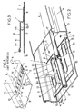
- la figure 2 est une vue en perspective d'un chemin de câbles incluant un support de câbles électriques selon une première forme de réalisation de l'invention,
- la figure 3 est une vue en coupe longitudinale du chemin de câbles de la figure 2,
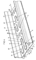
- et la figure 4 est une vue en perspective d'un support de câbles électriques selon une deuxième forme de réalisation, constituant par lui-même un chemin de câbles.
- FIG. 1 is a perspective view of a cable tray including a support for electrical cables of the prior art,
- FIG. 2 is a perspective view of a cable tray including an electrical cable support according to a first embodiment of the invention,
- Figure 3 is a longitudinal sectional view of the cable tray in Figure 2,
- and Figure 4 is a perspective view of an electrical cable support according to a second embodiment, constituting by itself a cable tray.
Sur les différentes figures, les mêmes références désignent des éléments identiques ou similaires.In the different figures, the same references designate identical or similar elements.
La première forme de réalisation de l'invention concerne, de façon générale, les supports 1 de câbles électriques du genre de celui, connu en soi, qui est représenté sur la figure 1 et qui est commercialisé sous la marque "ZPS" par la Société Constructions Electriques de la Seine.The first embodiment of the invention relates, in general, to the supports 1 of electric cables of the type of that known per se, which is represented in FIG. 1 and which is marketed under the brand "ZPS" by the Company Electric constructions of the Seine.
Ces supports 1 peuvent être fixés sur toute surface d'appui rigide, par exemple sur un mur, ou encore sur le fond 2 d'un profilé métallique 3 à section en U qui présente par ailleurs deux parois latérales 4. Ces deux parois latérales 4 délimitent avec le fond 2 une rigole qui peut être le cas échéant recouverte par un couvercle et qui est destinée à recevoir des câbles électriques s'étendant selon une direction longitudinale X.These supports 1 can be fixed on any rigid support surface, for example on a wall, or on the
Le support de câble 1 est constitué par une tôle pliée et découpée, réalisée par exemple en acier galvanisé d'une épaisseur de 0,8 à 2 mm. Ce support 1 s'étend selon la direction longitudinale X entre, d'une part, un bord arrière 5 perpendiculaire à la direction X et, d'autre part, un bord avant 6 roulé, lui-même perpendiculaire à la direction X.The cable support 1 consists of a folded and cut sheet, made for example of galvanized steel with a thickness of 0.8 to 2 mm. This support 1 extends in the longitudinal direction X between, on the one hand, a
Plus précisément, le support 1 comprend :
- une paroi de fixation plane 7 qui est fixée sur le
fond 2 du chemin de câble par des poinçonnages partiels 8 constituant chacun un rivetage dit "autorivetage", ou encore par soudure, par vissage, ou autres, cette paroi de fixation 7 s'étendant selon la direction longitudinale X depuis le bord arrière 5 jusqu'à une portion coudée 9 formant un ressaut, - et une paroi d'accrochage 10 de forme générale plane et parallèle à la paroi de fixation 7, cette paroi d'accrochage 10 s'étendant parallèlement à la direction longitudinale X à l'opposé de la paroi de fixation 7, depuis la portion coudée 9 jusqu'au bord avant 6.
- a flat fixing wall 7 which is fixed to the
bottom 2 of the cable tray bypartial punctures 8 each constituting a riveting called "self-leveling", or even by welding, by screwing, or the like, this fixing wall 7 extending in the longitudinal direction X from therear edge 5 to abent portion 9 forming a projection, - and a
hooking wall 10 of general shape flat and parallel to the fixing wall 7, thishooking wall 10 extending parallel to the longitudinal direction X opposite the fixing wall 7, from thebent portion 9 to thefront edge 6.
Afin de pouvoir attacher des câbles électriques sur la face "supérieure" 10a de la paroi de fixation 10 au moyen de colliers de serrage, cette paroi de fixation présente une pluralité de trous oblongs 11 juxtaposés qui s'étendent chacun selon la direction longitudinale X.In order to be able to attach electrical cables to the "upper"
De plus, afin de permettre à un opérateur de glisser son doigt sous la paroi de fixation 10 lors du passage des colliers de serrage dans les trous oblongs 11, la sous-face de la paroi de fixation est située à une hauteur relativement importante au-dessus du fond 2 du chemin de câbles, cette hauteur étant par exemple supérieure à 2 cm.In addition, in order to allow an operator to slide his finger under the
Comme représenté sur les figures 2 et 3, afin d'éviter que les opérateurs aient à glisser leurs doigts sous la paroi de fixation 10 lors de la mise en place des colliers de serrage, la première forme de réalisation de l'invention prévoit de remplacer les trous oblongs 11 par des fentes 12 en forme de U, de préférence toutes identiques.As shown in FIGS. 2 and 3, in order to prevent operators from having to slide their fingers under the
Chacune de ces fentes 12 présente deux branches latérales 12a sensiblement rectilignes reliées entre elles par un tronçon courbe 12b en arc-de-cercle.Each of these
Les deux branches latérales 12a de chaque fente s'étendent sensiblement parallèlement à la direction longitudinale X, de sorte que chaque fente 12 délimite un doigt d'accrochage 13 qui s'étend lui-même sensiblement parallèlement à la direction longitudinale X entre une première extrémité 14 éloignée du tronçon courbe 12b et une deuxième extrémité 15 ou extrémité libre, au niveau dudit tronçon courbe.The two
De préférence, chaque fente 12 présente une largeur comprise entre 2 et 5 mm, et chaque doigt d'accrochage 13 présente lui-même une largeur e qui, mesurée perpendiculairement à la direction longitudinale X, est comprise entre 0,5 et 2 cm.Preferably, each
Grâce à ces dispositions, lorsqu'il est nécessaire de fixer un ou plusieurs câbles 17 sur le support 1 au moyen d'un collier de serrage 18, on plie ce collier de façon qu'il présente une zone courbe, et l'on engage ladite zone courbe sous l'un des doigts d'accrochage 13, en faisant pénétrer cette zone courbe du collier dans le tronçon courbe 12b de la fente en U correspondante.Thanks to these provisions, when it is necessary to fix one or
Une fois le collier de serrage 18 passé sous les doigts d'accrochage 13, on serre ce collier sur le ou les câbles 17 et le doigt 13.Once the
Après cette opération de serrage, le collier 18 peut tout au plus se déplacer en translation axiale par la direction X, de sorte que ce collier ne peut pas se dégager du doigt d'accrochage 13 correspondant dans la mesure où il ne peut plus subir un mouvement de rotation qui lui permettrait de sortir de la fente 12 par la portion courbe 12b de cette fente.After this tightening operation, the
Du fait que l'opérateur chargé de mettre en place le collier de serrage 18 n'a plus à glisser ses doigts sous la paroi d'accrochage 10, la hauteur H entre la sous-face 10b de cette paroi d'accrochage et la ligne de base 16 correspondant au fond 2 du chemin de câble peut être réduite à une valeur généralement inférieure à 1 cm, et avantageusement de l'ordre de 6 mm.Because the operator responsible for fitting the
De préférence, comme représenté sur la figure 2, les fentes 12 du support 1 sont réparties en deux rangées transversales 19, 20 et sont disposées de façon que les doigts 13 correspondant à la rangée 20 soient décalés par rapport au doigt d'accrochage 13 correspondant à la rangée 19, dans une direction transversale Y perpendiculaire à la direction X et parallèle au fond 2 du profilé.Preferably, as shown in FIG. 2, the
Plus exactement, les doigts d'accrochage 13 de chaque rangée 19, 20 sont disposés à intervalles réguliers dans la direction transversale Y, selon un pas constant P mesurant par exemple entre 1 et 4 cm, et, d'une rangée à l'autre, les doigts d'accrochage 13 sont décalés d'une distance P/2 selon la direction transversale Y.More precisely, the hooking
De plus, les doigts d'accrochage 13 de chaque rangée 19, 20 s'étendent de préférence à l'opposé de l'autre des rangées 19, 20, depuis leur première extrémité 14 vers leur deuxième extrémité 15, ce qui peut faciliter la mise en place des colliers de serrage 18 sur les doigts d'accrochage 13, lorsque des câbles 17 ont déjà été mis en place sur le support 1.In addition, the hooking
Dans la deuxième forme de réalisation de l'invention représentée sur la figure 4, le support de câble est constitué par le profilé 3 lui-même, qui est similaire au profilé déjà décrit précédemment, à ceci près que les fentes 12 sont ménagées dans le fond 2 de ce profilé.In the second embodiment of the invention shown in Figure 4, the cable support is constituted by the profile 3 itself, which is similar to the profile already described above, except that the
Les fentes 12 sont similaires à celles déjà décrites et elles sont de préférence réparties en groupe de deux rangées transversales contiguës 19, 20 comme dans la forme de réalisation des figures 2 et 3 : la forme des fentes 12 et des doigts d'accrochage 13, ainsi que leur disposition dans les rangées transversales 19, 20, ne seront donc pas décrites en détail ici.The
Les groupes de deux rangées transversales 19, 20 sont répétés à intervalles réguliers sur la longueur du profilé 3, ces groupes de rangées 19, 20 pouvant être éventuellement séparés les uns des autres par une ou plusieurs rangées 21, de trous oblongs 22 s'étendant chacun parallèlement à la direction longitudinale X.The groups of two
Claims (10)
Applications Claiming Priority (3)
| Application Number | Priority Date | Filing Date | Title |
|---|---|---|---|
| FR9607308A FR2749913B1 (en) | 1996-06-12 | 1996-06-12 | SUPPORT FOR ELECTRIC CABLES AND CABLE ROUTE COMPRISING SUCH SUPPORTS |
| FR9607308 | 1996-06-12 | ||
| CZ19973734A CZ293321B6 (en) | 1996-06-12 | 1997-11-26 | Carrier of electric cables and cable tray being provided with such carrier |
Publications (2)
| Publication Number | Publication Date |
|---|---|
| EP0813012A1 true EP0813012A1 (en) | 1997-12-17 |
| EP0813012B1 EP0813012B1 (en) | 2000-08-02 |
Family
ID=25746923
Family Applications (1)
| Application Number | Title | Priority Date | Filing Date |
|---|---|---|---|
| EP97401293A Expired - Lifetime EP0813012B1 (en) | 1996-06-12 | 1997-06-09 | Electrical cable support and cable duct with such supports |
Country Status (5)
| Country | Link |
|---|---|
| EP (1) | EP0813012B1 (en) |
| CZ (1) | CZ293321B6 (en) |
| DE (1) | DE69702691T2 (en) |
| ES (1) | ES2151233T3 (en) |
| FR (1) | FR2749913B1 (en) |
Cited By (7)
| Publication number | Priority date | Publication date | Assignee | Title |
|---|---|---|---|---|
| FR2781936A1 (en) * | 1998-08-03 | 2000-02-04 | Const Electr De La Seine Ces | CABLE PATH |
| EP1113552A1 (en) * | 1999-12-28 | 2001-07-04 | K 2000 S.R.L. | Cable channel with inwardly projecting parts for passing through ties |
| FR2888056A1 (en) * | 2005-07-01 | 2007-01-05 | Rehau Sa | Linear fixation element e.g. clamp collar, retaining structure for e.g. chute, has longitudinal branch with free end and end coupled to chute base wall, and lateral extensions placed on both sides of branch to fix partition wall by clipsage |
| FR2928046A1 (en) * | 2008-02-26 | 2009-08-28 | Alstom Transport Sa | DEVICE FOR FIXING A PLURALITY OF CABLES COMBINED BETWEEN THEM |
| US20140021309A1 (en) * | 2012-07-18 | 2014-01-23 | Panduit Corp. | Metal Wall Bracket |
| US20190027909A1 (en) * | 2017-07-24 | 2019-01-24 | Alstom Transport Technologies | Cable Tray With Fixing Holes |
| CN114304236A (en) * | 2021-12-27 | 2022-04-12 | 区文锟 | Rotary mincing device |
Families Citing this family (2)
| Publication number | Priority date | Publication date | Assignee | Title |
|---|---|---|---|---|
| US7459633B2 (en) | 2006-07-11 | 2008-12-02 | Vantage Point Products Corp. | Wire management system |
| DE102013107181A1 (en) | 2013-07-08 | 2015-01-08 | Bombardier Transportation Gmbh | Fastening device for cables, as well as method for attaching cables |
Citations (2)
| Publication number | Priority date | Publication date | Assignee | Title |
|---|---|---|---|---|
| FR2138092A7 (en) * | 1971-05-19 | 1972-12-29 | Raymond A Ste | |
| FR2613550A1 (en) * | 1987-04-01 | 1988-10-07 | Spie Batignolles | Device for fixing a plurality of cables to a support |
-
1996
- 1996-06-12 FR FR9607308A patent/FR2749913B1/en not_active Expired - Lifetime
-
1997
- 1997-06-09 ES ES97401293T patent/ES2151233T3/en not_active Expired - Lifetime
- 1997-06-09 DE DE69702691T patent/DE69702691T2/en not_active Expired - Lifetime
- 1997-06-09 EP EP97401293A patent/EP0813012B1/en not_active Expired - Lifetime
- 1997-11-26 CZ CZ19973734A patent/CZ293321B6/en not_active IP Right Cessation
Patent Citations (2)
| Publication number | Priority date | Publication date | Assignee | Title |
|---|---|---|---|---|
| FR2138092A7 (en) * | 1971-05-19 | 1972-12-29 | Raymond A Ste | |
| FR2613550A1 (en) * | 1987-04-01 | 1988-10-07 | Spie Batignolles | Device for fixing a plurality of cables to a support |
Cited By (15)
| Publication number | Priority date | Publication date | Assignee | Title |
|---|---|---|---|---|
| FR2781936A1 (en) * | 1998-08-03 | 2000-02-04 | Const Electr De La Seine Ces | CABLE PATH |
| EP0978915A1 (en) * | 1998-08-03 | 2000-02-09 | Société de Constructions Electriques de la Seine ( CES) | Cableway |
| US6254041B1 (en) | 1998-08-03 | 2001-07-03 | Societe De Constructions Eleciriques De La Seine (Ces) | Cable conduit |
| EP1113552A1 (en) * | 1999-12-28 | 2001-07-04 | K 2000 S.R.L. | Cable channel with inwardly projecting parts for passing through ties |
| FR2888056A1 (en) * | 2005-07-01 | 2007-01-05 | Rehau Sa | Linear fixation element e.g. clamp collar, retaining structure for e.g. chute, has longitudinal branch with free end and end coupled to chute base wall, and lateral extensions placed on both sides of branch to fix partition wall by clipsage |
| FR2928046A1 (en) * | 2008-02-26 | 2009-08-28 | Alstom Transport Sa | DEVICE FOR FIXING A PLURALITY OF CABLES COMBINED BETWEEN THEM |
| WO2009112754A2 (en) * | 2008-02-26 | 2009-09-17 | Alstom Transport Sa | Device for attaching a plurality of cables grouped together |
| WO2009112754A3 (en) * | 2008-02-26 | 2009-12-23 | Alstom Transport Sa | Device for attaching a plurality of cables grouped together |
| US20140021309A1 (en) * | 2012-07-18 | 2014-01-23 | Panduit Corp. | Metal Wall Bracket |
| US8936221B2 (en) * | 2012-07-18 | 2015-01-20 | Panduit Corp. | Metal wall bracket |
| US20190027909A1 (en) * | 2017-07-24 | 2019-01-24 | Alstom Transport Technologies | Cable Tray With Fixing Holes |
| FR3069385A1 (en) * | 2017-07-24 | 2019-01-25 | Alstom Transport Technologies | CABLE PATH WITH ORIFICES OF ATTACHE |
| EP3435500A1 (en) * | 2017-07-24 | 2019-01-30 | ALSTOM Transport Technologies | Cable path with fastener holes |
| CN114304236A (en) * | 2021-12-27 | 2022-04-12 | 区文锟 | Rotary mincing device |
| CN114304236B (en) * | 2021-12-27 | 2023-11-07 | 区文锟 | Rotary mincing device |
Also Published As
| Publication number | Publication date |
|---|---|
| EP0813012B1 (en) | 2000-08-02 |
| DE69702691D1 (en) | 2000-09-07 |
| ES2151233T3 (en) | 2000-12-16 |
| FR2749913B1 (en) | 1998-08-28 |
| FR2749913A1 (en) | 1997-12-19 |
| CZ373497A3 (en) | 1999-06-16 |
| DE69702691T2 (en) | 2001-03-29 |
| CZ293321B6 (en) | 2004-04-14 |
Similar Documents
| Publication | Publication Date | Title |
|---|---|---|
| CA2614600C (en) | Splice bar for connecting cable tray sections | |
| EP1192693A1 (en) | Accessory for fixing a wire cable tray, and wire cable tray equipped with at least such an accessory | |
| EP2115837B1 (en) | Attachment device for a yarn cable track | |
| FR2766897A1 (en) | WIRE CABLE PATH HAVING AT LEAST ONE FIXING ACCESSORY, AND CORRESPONDING FIXING ACCESSORY | |
| EP1127394B1 (en) | Device for fixing a wire on a carrier element provided with at least an opening and carrier assembly for cable troughs comprising at least said device | |
| EP0382597A1 (en) | Extruded section, such as a gutter, plinth, trunking or the like, for accommodation and protection, in particular of electrical devices and supply leads | |
| EP0978915B1 (en) | Cableway | |
| WO2005062436A2 (en) | Accessory for lifting and bonding wire cable trays | |
| EP0813012B1 (en) | Electrical cable support and cable duct with such supports | |
| EP0986849B1 (en) | Wiring duct and accessory capable of being directly mounted on said wiring duct | |
| EP1498995A1 (en) | Supporting bracket for cable channel | |
| FR2711208A1 (en) | Fish plate for joining lengths of cable ducting together | |
| FR2766905A1 (en) | Folded section girder for building construction | |
| EP1376798A1 (en) | Conduit meshsupport | |
| FR2749914A1 (en) | Ducting support structure for cables | |
| EP1542329B1 (en) | Mounting bracket for cable channels | |
| EP0725467B1 (en) | Fixation device for assembling metal sheet-cable ducts | |
| FR2698428A1 (en) | Cover element for cable tray element. | |
| FR2725780A1 (en) | METHOD FOR FASTENING A NOZZLE ON A COOLING RADIATOR | |
| FR2766904A1 (en) | C- sectional steel girder for building | |
| FR2852156A1 (en) | Pipe support for supporting electrical wires in raceway, has two lateral flanges spreading from base to free end, where free end is covered by rigid profile e.g. folded sheet, integrated to flange | |
| FR2749912A1 (en) | Channel ducting for cables | |
| FR2849297A1 (en) | COUPLING ACCESSORY FOR CHUTE BASE | |
| EP0983408A1 (en) | Roof cover element | |
| FR2866163A1 (en) | Support bracket for positioning raceway, has free end with groove formed between one end of support surface and return flange, where groove temporarily hooks cover of raceway after positioning raceway on bracket |
Legal Events
| Date | Code | Title | Description |
|---|---|---|---|
| PUAI | Public reference made under article 153(3) epc to a published international application that has entered the european phase |
Free format text: ORIGINAL CODE: 0009012 |
|
| AK | Designated contracting states |
Kind code of ref document: A1 Designated state(s): BE CH DE ES GB IT LI NL SE |
|
| 17P | Request for examination filed |
Effective date: 19980121 |
|
| AKX | Designation fees paid |
Free format text: BE CH DE ES GB IT LI NL SE |
|
| RBV | Designated contracting states (corrected) |
Designated state(s): BE CH DE ES GB IT LI NL SE |
|
| 17Q | First examination report despatched |
Effective date: 19990720 |
|
| GRAG | Despatch of communication of intention to grant |
Free format text: ORIGINAL CODE: EPIDOS AGRA |
|
| GRAG | Despatch of communication of intention to grant |
Free format text: ORIGINAL CODE: EPIDOS AGRA |
|
| GRAH | Despatch of communication of intention to grant a patent |
Free format text: ORIGINAL CODE: EPIDOS IGRA |
|
| 17Q | First examination report despatched |
Effective date: 19990720 |
|
| RIC1 | Information provided on ipc code assigned before grant |
Free format text: 7F 16L 3/26 A, 7H 02G 3/04 B, 7H 02G 3/30 B |
|
| GRAH | Despatch of communication of intention to grant a patent |
Free format text: ORIGINAL CODE: EPIDOS IGRA |
|
| GRAA | (expected) grant |
Free format text: ORIGINAL CODE: 0009210 |
|
| AK | Designated contracting states |
Kind code of ref document: B1 Designated state(s): BE CH DE ES GB IT LI NL SE |
|
| REG | Reference to a national code |
Ref country code: CH Ref legal event code: EP |
|
| REF | Corresponds to: |
Ref document number: 69702691 Country of ref document: DE Date of ref document: 20000907 |
|
| REG | Reference to a national code |
Ref country code: CH Ref legal event code: NV Representative=s name: ANDRE ROLAND CONSEILS EN PROPRIETE INTELLECTUELLE |
|
| ITF | It: translation for a ep patent filed | ||
| GBT | Gb: translation of ep patent filed (gb section 77(6)(a)/1977) |
Effective date: 20001030 |
|
| REG | Reference to a national code |
Ref country code: ES Ref legal event code: FG2A Ref document number: 2151233 Country of ref document: ES Kind code of ref document: T3 |
|
| PLBE | No opposition filed within time limit |
Free format text: ORIGINAL CODE: 0009261 |
|
| STAA | Information on the status of an ep patent application or granted ep patent |
Free format text: STATUS: NO OPPOSITION FILED WITHIN TIME LIMIT |
|
| 26N | No opposition filed | ||
| REG | Reference to a national code |
Ref country code: GB Ref legal event code: IF02 |
|
| REG | Reference to a national code |
Ref country code: NL Ref legal event code: TD Effective date: 20110701 |
|
| PGFP | Annual fee paid to national office [announced via postgrant information from national office to epo] |
Ref country code: CH Payment date: 20110526 Year of fee payment: 15 Ref country code: SE Payment date: 20110603 Year of fee payment: 15 Ref country code: ES Payment date: 20110609 Year of fee payment: 15 |
|
| BECA | Be: change of holder's address |
Owner name: CTS CABLE TRAY SYSTEMS SAS186 AVENUE DE LA FERME D Effective date: 20110706 |
|
| PGFP | Annual fee paid to national office [announced via postgrant information from national office to epo] |
Ref country code: GB Payment date: 20110606 Year of fee payment: 15 |
|
| PGFP | Annual fee paid to national office [announced via postgrant information from national office to epo] |
Ref country code: IT Payment date: 20110527 Year of fee payment: 15 |
|
| REG | Reference to a national code |
Ref country code: DE Ref legal event code: R082 Ref document number: 69702691 Country of ref document: DE Representative=s name: PATENTANWAELTE HEYERHOFF & GEIGER, DE |
|
| REG | Reference to a national code |
Ref country code: ES Ref legal event code: PC2A Owner name: CTS CABLE TRAY SYSTEMS SAS Effective date: 20111104 |
|
| REG | Reference to a national code |
Ref country code: DE Ref legal event code: R082 Ref document number: 69702691 Country of ref document: DE Representative=s name: HEYERHOFF GEIGER & PARTNER PATENTANWAELTE, DE Effective date: 20111007 Ref country code: DE Ref legal event code: R081 Ref document number: 69702691 Country of ref document: DE Owner name: CTS CABLE TRAY SYSTEMS SAS - CTS, FR Free format text: FORMER OWNER: SOCIETE DE CONSTRUCTIONS ELECTRIQUES DE LA SEINE (CES), ISSY-LES-MOULINEAU, FR Effective date: 20111007 |
|
| REG | Reference to a national code |
Ref country code: CH Ref legal event code: PCAR Free format text: ANDRE ROLAND S.A.;CASE POSTALE 5107;1002 LAUSANNE (CH) |
|
| REG | Reference to a national code |
Ref country code: SE Ref legal event code: EUG |
|
| REG | Reference to a national code |
Ref country code: CH Ref legal event code: PL |
|
| REG | Reference to a national code |
Ref country code: CH Ref legal event code: PL |
|
| GBPC | Gb: european patent ceased through non-payment of renewal fee |
Effective date: 20120609 |
|
| PG25 | Lapsed in a contracting state [announced via postgrant information from national office to epo] |
Ref country code: IT Free format text: LAPSE BECAUSE OF NON-PAYMENT OF DUE FEES Effective date: 20120609 Ref country code: SE Free format text: LAPSE BECAUSE OF NON-PAYMENT OF DUE FEES Effective date: 20120610 |
|
| PG25 | Lapsed in a contracting state [announced via postgrant information from national office to epo] |
Ref country code: CH Free format text: LAPSE BECAUSE OF NON-PAYMENT OF DUE FEES Effective date: 20120630 Ref country code: LI Free format text: LAPSE BECAUSE OF NON-PAYMENT OF DUE FEES Effective date: 20120630 Ref country code: GB Free format text: LAPSE BECAUSE OF NON-PAYMENT OF DUE FEES Effective date: 20120609 |
|
| PGFP | Annual fee paid to national office [announced via postgrant information from national office to epo] |
Ref country code: DE Payment date: 20130621 Year of fee payment: 17 |
|
| PGFP | Annual fee paid to national office [announced via postgrant information from national office to epo] |
Ref country code: BE Payment date: 20130624 Year of fee payment: 17 |
|
| REG | Reference to a national code |
Ref country code: ES Ref legal event code: FD2A Effective date: 20131018 |
|
| PG25 | Lapsed in a contracting state [announced via postgrant information from national office to epo] |
Ref country code: ES Free format text: LAPSE BECAUSE OF NON-PAYMENT OF DUE FEES Effective date: 20120610 |
|
| PGFP | Annual fee paid to national office [announced via postgrant information from national office to epo] |
Ref country code: NL Payment date: 20130624 Year of fee payment: 17 |
|
| REG | Reference to a national code |
Ref country code: DE Ref legal event code: R119 Ref document number: 69702691 Country of ref document: DE |
|
| REG | Reference to a national code |
Ref country code: NL Ref legal event code: V1 Effective date: 20150101 |
|
| PG25 | Lapsed in a contracting state [announced via postgrant information from national office to epo] |
Ref country code: NL Free format text: LAPSE BECAUSE OF NON-PAYMENT OF DUE FEES Effective date: 20150101 |
|
| REG | Reference to a national code |
Ref country code: DE Ref legal event code: R119 Ref document number: 69702691 Country of ref document: DE Effective date: 20150101 |
|
| PG25 | Lapsed in a contracting state [announced via postgrant information from national office to epo] |
Ref country code: DE Free format text: LAPSE BECAUSE OF NON-PAYMENT OF DUE FEES Effective date: 20150101 |
|
| PG25 | Lapsed in a contracting state [announced via postgrant information from national office to epo] |
Ref country code: BE Free format text: LAPSE BECAUSE OF NON-PAYMENT OF DUE FEES Effective date: 20140630 |