EP0812967A2 - Automatic system for personal hygiene following the carrying out of bodily functions - Google Patents
Automatic system for personal hygiene following the carrying out of bodily functions Download PDFInfo
- Publication number
- EP0812967A2 EP0812967A2 EP97830281A EP97830281A EP0812967A2 EP 0812967 A2 EP0812967 A2 EP 0812967A2 EP 97830281 A EP97830281 A EP 97830281A EP 97830281 A EP97830281 A EP 97830281A EP 0812967 A2 EP0812967 A2 EP 0812967A2
- Authority
- EP
- European Patent Office
- Prior art keywords
- sanitary bowl
- designed
- control device
- circuit
- subsidiary
- Prior art date
- Legal status (The legal status is an assumption and is not a legal conclusion. Google has not performed a legal analysis and makes no representation as to the accuracy of the status listed.)
- Withdrawn
Links
Images


Classifications
-
- E—FIXED CONSTRUCTIONS
- E03—WATER SUPPLY; SEWERAGE
- E03D—WATER-CLOSETS OR URINALS WITH FLUSHING DEVICES; FLUSHING VALVES THEREFOR
- E03D9/00—Sanitary or other accessories for lavatories ; Devices for cleaning or disinfecting the toilet room or the toilet bowl; Devices for eliminating smells
- E03D9/08—Devices in the bowl producing upwardly-directed sprays; Modifications of the bowl for use with such devices ; Bidets; Combinations of bowls with urinals or bidets; Hot-air or other devices mounted in or on the bowl, urinal or bidet for cleaning or disinfecting
Definitions
- the present invention relates to an automatic system for personal hygiene following the carrying out of bodily functions.
- the system in question is intended to be used in any sanitary room in domestic dwellings, communal premises, hospitals, etc., for automatically effecting personal hygiene after the carrying out of one's normal bodily functions.
- the system according to the present invention may be advantageously used by persons who are not self-sufficient (for example, elderly people), allowing them to clean themselves in an autonomous manner immediately after (or during) the carrying out of their bodily functions.
- the system in question may advantageously also be used in the sanitary premises of a conventional dwelling in keeping with the standards required for thorough and convenient hygiene.
- this system of the known type has the drawback that it does not alLow varied cleaning of the front and rear zone of the user. This has a negative effect in terms of the flexibility and versatility of operating performance which, for example, does not allow one to repeat several times washing of the single zone concerned.
- the main object of the present invention is therefore that of overcoming the drawbacks of the known art, by providing a system for personal hygiene following the carrying out of bodily functions, which uses equipment which is readily available commercially and low-cost, thus ensuring for the user a high degree of flexibility of use aimed at satisfying every specific requirement.
- the present invention allows varied washing of the front and rear intimate zones of the user.
- a further object of the system in question is that it should be reliable, safe and be equipped with a device for aspiration of the odours, which is connected directly to the sanitary bowl.
- 1 denotes in its entirety the automatic system for personal hygiene following the carrying out of bodily functions, according to the present invention.
- Said system comprises substantially a sanitary bowl 2 connected to a hot-air generator 3 by means of a ventilation circuit 4, and a hot-water generator 5 connected in turn by means of a hydraulic circuit 6 to the water supply mains 7. It also envisages the use of an electronic control device 8 designed to activate operation of the system in accordance with programmed operating steps.
- the hydraulic circuit 6 is divided up by a flow distributor 11 into two subsidiary circuits, a first one 9 and a second one 10, which are substantially identical and connected, upstream, to the water supply mains 7 and, downstream, to the front part 12 and rear part 13 of the sanitary bowl 2, respectively.
- Each subsidiary circuit 9 and 10 comprises a first delivery pump 14 connected electrically to the control device 8 and provided with a first non-return valve 15 arranged downstream thereof.
- a first thermal heating element 16 which is also operated by the control device 8.
- Each subsidiary circuit 9 and 10 has flowing into it, upstream of the first thermal heating element 16, a soap-conveying pipe 17 connected by means of a suction pump 18 provided with a second non-return valve 19, to a soap storage container 20.
- the latter is advantageously provided with a sensor 21 which is able to detect the absence of the water and soap mixture and signal it immediately by means of an indicator lamp L.
- the first subsidiary circuit 9 and second subsidiary circuit 10 are provided, at their end sections associated with the sanitary bowl 2, respectively with a fanatomizing spray nozzle 23 and a nozzle 24 with a concentrated and directed jet (see Figs. 1, 3 and 5).
- the hot-air generator 3 consists of a second thermal heating element 25, electrically governed by the control device 8, and a ventilation circuit 4 provided, at one end associated with the sanitary bowl, with two nozzles for delivery of the air, one 26 being arranged in the front part 12, and the other 27 being arranged in the rear part 13 of the sanitary bowl 2 (see Fig. 5).
- the sanitary bowl 2 is also provided with a conventional device 28 for flushing thereof (controlled by a flow meter or conventional cistern and float) and an odour aspirator device 29 connected, by means of a suction pipe 30, to the internal volume of the sanitary bowl 2 and, by means of an expulsion pipe 31, to a downstream section 32 of the siphon connected to the drainage system of the sanitary bowl 2 itself.
- a conventional device 28 for flushing thereof controlled by a flow meter or conventional cistern and float
- an odour aspirator device 29 connected, by means of a suction pipe 30, to the internal volume of the sanitary bowl 2 and, by means of an expulsion pipe 31, to a downstream section 32 of the siphon connected to the drainage system of the sanitary bowl 2 itself.
- auxiliary hydraulic circuit 33 connected to the water supply mains 7 and to the sanitary bow1 2 in order to convey a continuous supply of water to an encrusted zone of the sanitary bowl 2.
- This auxiliary hydraulic circuit 33 has inserted along it a second delivery pump 34 also governed by the control device 8.
- the seating rim 35 of the sanitary bowl 2 has mounted on it two activating pushbuttons 36 which can be easily reached by the user and are designed to transmit two corresponding signals to the control device 8.
- the user is able to activate the first, the second or both the subsidiary circuits 9, 10, thus performing washing of the front zone only, the rear zone only or both the front and rear zones.
- the control device 8 activates a washing cycle consisting substantially of four cleaning stages: a first one involving washing with hot water; a second one involving washing with hot water and soap; a third one involving rinsing with water; and a fourth one involving drying with hot air.
- a sensor 37 for detecting the presence of a person, capable of transmitting a signal to the control device when a user occupies the sitting position.
- This signal causes, during a first stage of operation of the system 1, activation of the first thermal heating element 16 and the second delivery pump 34.
- Activation of the second delivery pump 34 causes the prompt supply of a flow of water into the encrusted zone so as to avoid subsequent inconvenient operations involving cleaning of the sanitary bowl 2.
- the first thermal heating element 16 As a result of activation of the first thermal heating element 16, it is possible to perform advanced preheating thereof, intended to ensure the production of a flow of hot water (at the desired temperature) immediately after activaticn of the cleaning stages by the control device 8.
- the system in question has moreover, if required, a seating reducer device 55 having a perimetral configuration similar to that defined by the seating rim 35, but being provided with a central opening 56 having a size suitable for the seating of children.
- This central opening 56 has dimensions smaller than those defined by the seating rim 35.
- the seating rim 35 forms a single body with the sanitary bowl 2 and consists of two shells which can be fixed to one another.
- the latter is mounted on top of the sanitary bowl 2 (by means of screws 62) and is designed to house the following elements: atomizer spray nozzle 23, nozzle 24 with a concentrated and directed jet, the end sections of the activating pushbutton circuits 36 and the sensor 37 for detecting the presence of a person, the air delivery nozzles 26, 27, the end sections of the subsidiary circuits 9, 10, the end section of the auxiliary hydraulic circuit 33, the end section of the conventional flushing device 28, the end section of the ventilation device 4, and the initial section of the suction pipe 30.
- a second upper shell 61 is mounted above the first bottom shell 60 so as to form therewith the seating rim 35, providing a sealed closure.
- the conventional device 28 used for flushing, all the pumps 14, 18, 34, the hydraulic circuits 6, 9, 10, 33, ventilation circuit 4 and electrical circuits, the non-return valves 15, 19, the soap storage container 20 and the control device 8 are arranged in a column 38 mounted behind the sanitary bowl 2 so as to limit the overall dimensions of the system 1 and provide a cortaining structure which is externally pleasing and occupies little space.
- the electrical power supply consists of a low voltage with a value which is not dangerous for the user of the system 1, an ac/dc voltage transformer being provided for this purpose.
- a continuity unit may also be used (not shown in the accompanying figures) for ensuring that the system 1 provides a permanent service even in the event of an interruption in the normal energy supply.
Abstract
Description
- The present invention relates to an automatic system for personal hygiene following the carrying out of bodily functions.
- The system in question is intended to be used in any sanitary room in domestic dwellings, communal premises, hospitals, etc., for automatically effecting personal hygiene after the carrying out of one's normal bodily functions. In particular, the system according to the present invention may be advantageously used by persons who are not self-sufficient (for example, elderly people), allowing them to clean themselves in an autonomous manner immediately after (or during) the carrying out of their bodily functions. In view of the low cost, the system in question may advantageously also be used in the sanitary premises of a conventional dwelling in keeping with the standards required for thorough and convenient hygiene.
- At present, as is known, there exists an automatic system for personal hygiene, described in Italian Patent Application No. 84119A/82, which envisages the use of a series of fairly complex apparatus connected in accordance with a logic/functional diagram which is not able to satisfy in an optimum manner the operational requirements of the user.
- In particular, this system of the known type has the drawback that it does not alLow varied cleaning of the front and rear zone of the user. This has a negative effect in terms of the flexibility and versatility of operating performance which, for example, does not allow one to repeat several times washing of the single zone concerned.
- It should be noted, moreover, that the use of an automatic system for personal hygiene obliges the user to remain in the premises assigned for this purpose for the whole of the time needed to perform the cycle of cleaning operations. Since this system is particularly suitable for persons who are not self-sufficient and who often need to be helped in their actions by other people (for example, in order to undress or dress themselves), remaining for a long time in an area where the air is inevitably contaminated may be a cause of discomfort.
- The system of the known type (see patent No. 84119A/82) has the drawback that it does not include any technical contrivance for reducing to a minimum the discomfort due to odours.
- The main object of the present invention is therefore that of overcoming the drawbacks of the known art, by providing a system for personal hygiene following the carrying out of bodily functions, which uses equipment which is readily available commercially and low-cost, thus ensuring for the user a high degree of flexibility of use aimed at satisfying every specific requirement. In particular, the present invention allows varied washing of the front and rear intimate zones of the user.
- A further object of the system in question is that it should be reliable, safe and be equipped with a device for aspiration of the odours, which is connected directly to the sanitary bowl.
- The technical characteristics of the invention, in accordance with the aforementioned objects, may be clearly understood from the contents of the claims indicated below and the advantages thereof will emerge more clearly in the detailed description which follows, provided with reference to the accompanying drawings which show a purely exemplary and non-limiting example of embodiment thereof, in which:
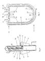
- Figure 1 shows the logic/functional diagram of the principle for installation of the system according to the present invention, in a combined arrangement of the equipment and circuits associated therewith, which make up the system itself;
- Figure 2 shows in schematic form a front view of the system in question, with some parts removed so that others may be seen more clearly;
- Figure 3 shows in schematic form a side view of the system in question, sectioned along the line indicated by III-III in Fig. 2;
- Figure 4 shows in schematic form a rear view of the system according to Fig. 2, with some parts removed so that others may be seen more clearly;
- Figure 5 shows in schematic form a view of an enlarged detail of the system in question, sectioned along the line V-V in Fig. 2;
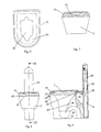
- Fig. 6 shows in schematic form a plan view of an accessory (seating reducer device) of the system in question;
- Fig. 7 shows in schematic form a front view of the system in question with the accessory according to Fig. 6, with some parts removed so that others may be seen more clearly;
- Figs. 8 and 9 show, respectively, a front view and a sectional view along the line IX-IX of Fig. 8 of the system in question, with a detail (relating to the seating rim) shown in the form of a different constructional solution.
- In accordance with the Figures of the accompanying drawings, 1 denotes in its entirety the automatic system for personal hygiene following the carrying out of bodily functions, according to the present invention.
- Said system comprises substantially a
sanitary bowl 2 connected to a hot-air generator 3 by means of aventilation circuit 4, and a hot-water generator 5 connected in turn by means of ahydraulic circuit 6 to the water supply mains 7. It also envisages the use of anelectronic control device 8 designed to activate operation of the system in accordance with programmed operating steps. - The
hydraulic circuit 6 is divided up by aflow distributor 11 into two subsidiary circuits, a first one 9 and a second one 10, which are substantially identical and connected, upstream, to the water supply mains 7 and, downstream, to thefront part 12 andrear part 13 of thesanitary bowl 2, respectively. Eachsubsidiary circuit first delivery pump 14 connected electrically to thecontrol device 8 and provided with a firstnon-return valve 15 arranged downstream thereof. - They have moreover inserted along them, downstream of the first
non-return valve 15 and upstream of thesanitary bowl 2, a first thermal heating element 16 which is also operated by thecontrol device 8. Eachsubsidiary circuit pipe 17 connected by means of asuction pump 18 provided with a secondnon-return valve 19, to asoap storage container 20. The latter is advantageously provided with asensor 21 which is able to detect the absence of the water and soap mixture and signal it immediately by means of an indicator lamp L. - The first
subsidiary circuit 9 and secondsubsidiary circuit 10 are provided, at their end sections associated with thesanitary bowl 2, respectively with a fanatomizingspray nozzle 23 and anozzle 24 with a concentrated and directed jet (see Figs. 1, 3 and 5). - The hot-
air generator 3 consists of a secondthermal heating element 25, electrically governed by thecontrol device 8, and aventilation circuit 4 provided, at one end associated with the sanitary bowl, with two nozzles for delivery of the air, one 26 being arranged in thefront part 12, and the other 27 being arranged in therear part 13 of the sanitary bowl 2 (see Fig. 5). - The
sanitary bowl 2 is also provided with aconventional device 28 for flushing thereof (controlled by a flow meter or conventional cistern and float) and anodour aspirator device 29 connected, by means of asuction pipe 30, to the internal volume of thesanitary bowl 2 and, by means of anexpulsion pipe 31, to adownstream section 32 of the siphon connected to the drainage system of thesanitary bowl 2 itself. - It should be noted that, in Figure 1, the electric circuits have been shown in thin lines and the hydraulic and ventilating circuits in bolder lines.
- Advantageously, it is envisaged using an auxiliary
hydraulic circuit 33 connected to the water supply mains 7 and to thesanitary bow1 2 in order to convey a continuous supply of water to an encrusted zone of thesanitary bowl 2. This auxiliaryhydraulic circuit 33 has inserted along it asecond delivery pump 34 also governed by thecontrol device 8. - The
seating rim 35 of thesanitary bowl 2 has mounted on it two activatingpushbuttons 36 which can be easily reached by the user and are designed to transmit two corresponding signals to thecontrol device 8. By means of the selective activation of one of the twopushbuttons 36 or both thepushbuttons 36 the user is able to activate the first, the second or both thesubsidiary circuits - When the user has performed selection of the zones to be washed by means of the aforementioned activating
pushbuttons 36, thecontrol device 8 activates a washing cycle consisting substantially of four cleaning stages: a first one involving washing with hot water; a second one involving washing with hot water and soap; a third one involving rinsing with water; and a fourth one involving drying with hot air. - On the
seating rim 35 of thesanitary bowl 2 there is also mounted asensor 37 for detecting the presence of a person, capable of transmitting a signal to the control device when a user occupies the sitting position. This signal causes, during a first stage of operation of the system 1, activation of the first thermal heating element 16 and thesecond delivery pump 34. Activation of thesecond delivery pump 34, as mentioned, causes the prompt supply of a flow of water into the encrusted zone so as to avoid subsequent inconvenient operations involving cleaning of thesanitary bowl 2. - As a result of activation of the first thermal heating element 16, it is possible to perform advanced preheating thereof, intended to ensure the production of a flow of hot water (at the desired temperature) immediately after activaticn of the cleaning stages by the
control device 8. - The system in question has moreover, if required, a
seating reducer device 55 having a perimetral configuration similar to that defined by theseating rim 35, but being provided with acentral opening 56 having a size suitable for the seating of children. Thiscentral opening 56 has dimensions smaller than those defined by theseating rim 35. - In a different constructional solution, the
seating rim 35 forms a single body with thesanitary bowl 2 and consists of two shells which can be fixed to one another. - In this way it is possible to mount all the components associated with the
seating rim 35 in a fixed manner on afirst bottom shell 60, i.e. without having to use flexible elements in order to allow theseating rim 35 to be raised and lowered. All the elements which in the preceding constructional solution were inserted inside the seating rim are now mounted more easily on thefirst bottom shell 60. The latter is mounted on top of the sanitary bowl 2 (by means of screws 62) and is designed to house the following elements:atomizer spray nozzle 23,nozzle 24 with a concentrated and directed jet, the end sections of the activatingpushbutton circuits 36 and thesensor 37 for detecting the presence of a person, theair delivery nozzles subsidiary circuits hydraulic circuit 33, the end section of theconventional flushing device 28, the end section of theventilation device 4, and the initial section of thesuction pipe 30. - A second
upper shell 61 is mounted above thefirst bottom shell 60 so as to form therewith theseating rim 35, providing a sealed closure. - As can be seen in Figure 4, the
conventional device 28 used for flushing, all thepumps hydraulic circuits ventilation circuit 4 and electrical circuits, thenon-return valves soap storage container 20 and thecontrol device 8 are arranged in acolumn 38 mounted behind thesanitary bowl 2 so as to limit the overall dimensions of the system 1 and provide a cortaining structure which is externally pleasing and occupies little space. - It should also be noted that the electrical power supply consists of a low voltage with a value which is not dangerous for the user of the system 1, an ac/dc voltage transformer being provided for this purpose.
- Advantageously a continuity unit may also be used (not shown in the accompanying figures) for ensuring that the system 1 provides a permanent service even in the event of an interruption in the normal energy supply.
Claims (11)
- Automatic system for personal hygiene following the carrying out of bodily functions, of the type involving flushing by a conventional valve device (28), comprising: a sanitary bowl (2) connected to said conventional device (28); a hot-water generator (5) associated with a first thermal heating element (16); a hydraulic circuit (6) connected to the water supply mains (7), designed to connect said hot-water generator (5) to said sanitary bowl (2); a soap storage container (20) linked to said hydraulic circuit; a hot-air gererator (3) connected to said sanitary bowl by means of a ventilation circuit (4) and associated with a second thermal heating element (25); a control device (8) designed to activate, in accordance with programmed operating steps, said hot-water generator (5), said suction pump (18), said hot-air generator (3); characterized in that it comprises: an odour aspirator device (29) connected to the sanitary bowl (2) by means of an air pipe (30, 31) and operated by said control device (8); a sensor (37) for detecting the presence of a person, mounted on the seating rim (35) of the sanitary bowl (2); said system (1) being moreover characterized in that said hydraulic circuit (6) is divided up by a flow distributor (11) into two subsidiary circuits (9, 10), a first one (9) of which being designed to perform frontal cleaning of a user of the system (1) and a second one (10) of which being designed to perform rear cleaning thereof, each said first subsidiary circuit (9) and second subsidiary circuit (10) being linked to said soap storage container (20) by means of a soap-conveying pipe (17) connected to a suction pump (18) and have inserted along it a first delivery pump (14) electrically governed by said control device (8) and designed to convey the water in a regulated manner from the water supply mains (7), via said first thermal heating element (16), to a front part (12) and to a rear part (13) of the sanitary bowl (2), respectively.
- Automatic system according to Claim 1, characterized in that comprises an auxiliary hydraulic circuit (33) which is connected to the water supply mains (7) and to the sanitary bowl (2) and which has inserted along it a second delivery pump (34) operated by said control device (8), said auxiliary hydraulic circuit (33) being designed to convey a continuous flow of water to an encrusted zone of the sanitary bowl (2).
- Automatic system according to Claim 1, characterized in that said first subsidiary circuit (9) and said second subsidiary circuit (10) are provided at their end sections associated with the sanitary bowl (2) respectively with at least one fan atomizer spray nozzle (23) and at least one nozzle (24) with a concentrated and directed jet.
- Automatic system according to Claim 1, characterized in that said odour aspirator device (29) is connected, by means of a suction pipe (30), inside the sanitary bowl (2) and, by means of an expulsion pipe (31), to a downstream section (32) of the siphon of the sanitary bowl (2).
- Automatic system according to Claim 1, characterized in that it comprises two activating pushbuttons (36) which are arranged on the seating rim (35) of the sanitary bowl (2) and are able to transmit two corresponding signals to the control device (8), designed to cause, selectively, operation of the first subsidiary circuit (9) and the second subsidiary circuit (10).
- Automatic system according to Claim 1, characterized in that said control device (8), when activated by said sensor (37) for detecting the presence of a person, causes, during a first operating stage of the system (1), activation of said first thermal heating element (16) and said second delivery pump (34).
- Automatic system according to Claim 1, characterized in that a soap-conveying pipe (17) is connected to said hydraulic circuit downstream of said first non-return valve (15) so as to allow improved mixing of the water with the soap.
- Automatic system according to Claims 1 and 5, characterized in that said control device (8) activates, when the user selects operation of at least one of the two subsidiary circuits (9, 10) by means of said activating pushbuttons (36), a washing cycle substantially consisting of four washing stages, namely a first one involving washing with hot water, a second one involving washing with hot water and soap, a third one involving rinsing with water and a fourth one involving drying with hot air.
- Automatic system according to Claim 1, characterized in that it comprises a seating reducer device (55) designed to be arranged on top of said seating rim (35), said seating reducer device (55) being provided with an external perimetral configuration similar to that of said seating rim (35) and being provided with a central opening (56) having a size suitable for the seating of children.
- Automatic system according to Claim 1, characterized in that said seating rim (35) forms a single body with said sanitary bowl (2).
- Automatic system according to Claim 1, characterized in that said seating rim consists of two shells which can be fixed to one another, i.e. a first bottom shell (60) fixed above the sanitary bowl (2) and designed to house said atomizer spray nozzle (23), said nozzle (24) with a concentrated and directed jet, the end sections of the electrical circuits associated with said activating pushbuttons (36) and with said sensor (37) for detecting the presence of persons, said air delivery nozzles (26, 27), the end sections of said subsidiary circuits (9, 10), the end section of said auxiliary hydraulic circuit (33), the end section of said conventional flushing device (28), the end section of said ventilation device (4), and the initial section of said suction pipe (30); and a second upper shell (61) being designed tc provide a hermetic closure on said bottom shell (60), forming therewith said seating rim (35).
Applications Claiming Priority (2)
| Application Number | Priority Date | Filing Date | Title |
|---|---|---|---|
| IT96VR000056A IT1289114B1 (en) | 1996-06-12 | 1996-06-12 | AUTOMATIC PLANT FOR HYGIENIC CLEANING AFTER PHYSIOLOGICAL FUNCTIONS |
| ITVR960056 | 1996-06-12 |
Publications (2)
| Publication Number | Publication Date |
|---|---|
| EP0812967A2 true EP0812967A2 (en) | 1997-12-17 |
| EP0812967A3 EP0812967A3 (en) | 1999-01-20 |
Family
ID=11428214
Family Applications (1)
| Application Number | Title | Priority Date | Filing Date |
|---|---|---|---|
| EP97830281A Withdrawn EP0812967A3 (en) | 1996-06-12 | 1997-06-10 | Automatic system for personal hygiene following the carrying out of bodily functions |
Country Status (4)
| Country | Link |
|---|---|
| US (1) | US5864894A (en) |
| EP (1) | EP0812967A3 (en) |
| CA (1) | CA2207450A1 (en) |
| IT (1) | IT1289114B1 (en) |
Cited By (1)
| Publication number | Priority date | Publication date | Assignee | Title |
|---|---|---|---|---|
| WO1999036635A1 (en) * | 1998-01-15 | 1999-07-22 | Rashpal Bains | Battery-operated bidet |
Families Citing this family (22)
| Publication number | Priority date | Publication date | Assignee | Title |
|---|---|---|---|---|
| CA2535244A1 (en) * | 2003-08-08 | 2005-02-17 | Dentsply International Inc. | Method and product for phosphosilicate slurry for use in dentistry and related bone cements |
| US20100266776A1 (en) * | 2009-04-21 | 2010-10-21 | Mt Industries, Inc. | Automated skin spray and dry system |
| US20110202019A1 (en) * | 2009-12-04 | 2011-08-18 | Mt Industries, Inc. | Hand held skin treatment spray system with air heating element |
| US8784390B2 (en) | 2009-12-04 | 2014-07-22 | Sunless, Inc. | Skin treatment spray nozzle system for automatic spray gantry |
| CN102587477A (en) * | 2011-01-06 | 2012-07-18 | 周锡卫 | Intelligent cleaning device for an exhaust-type stool device and control method |
| US8790319B2 (en) | 2011-07-15 | 2014-07-29 | Sunless, Inc. | Method and system for applying a heated skin treatment spray |
| EP2708288A3 (en) | 2012-09-17 | 2015-05-06 | Sunless, Inc. | Precision pumping system for spray treatment cycles |
| WO2016004313A1 (en) | 2014-07-03 | 2016-01-07 | Zohar Laufer | Personnel proximity detection and tracking system |
| US20180002911A1 (en) * | 2016-03-08 | 2018-01-04 | David R. Hall | Intelligent Position Dispensing Toilet Bidet System |
| WO2017193113A1 (en) * | 2016-05-06 | 2017-11-09 | Whole Bath, Llc | A seat and cover system with medicine units |
| CA3061246C (en) | 2016-05-06 | 2022-07-12 | Whole Bath, Llc | Drying nozzle apparatus |
| WO2017193111A1 (en) | 2016-05-06 | 2017-11-09 | Whole Bath, Llc | A seat and cover system with dynamic spray nozzle |
| US11458260B2 (en) | 2016-07-16 | 2022-10-04 | Bemis Manufacturing Company | Spray canister device with removable sleeved cover |
| US11479957B2 (en) * | 2016-05-06 | 2022-10-25 | Bemis Manufacturing Company | Medicine delivery, wash, clean and air dry system |
| US10869583B2 (en) | 2016-07-16 | 2020-12-22 | Whole Bath, Llc | Wash, clean and dry system with removable spray canister device |
| US11253114B2 (en) | 2016-05-06 | 2022-02-22 | Whole Bath, Llc | Wash, clean and dry system with removable spray canister device |
| US10982422B2 (en) | 2016-08-11 | 2021-04-20 | Whole Bath, Llc | Wash system with a cleanser assembly |
| US10563390B2 (en) | 2017-12-19 | 2020-02-18 | Whole Bath, Llc | Wash and clean apparatus |
| US11779167B2 (en) | 2019-01-02 | 2023-10-10 | Charles Agnew Osborne, Jr. | Dispensing and monitoring systems and methods |
| US11242192B2 (en) | 2019-05-30 | 2022-02-08 | Whole Bath, Llc | Spray canister device |
| US11445869B2 (en) | 2019-07-15 | 2022-09-20 | Bemis Manufacturing Company | Toilet seat assembly |
| US11739516B2 (en) | 2019-07-15 | 2023-08-29 | Bemis Manufacturing Company | Toilet seat assembly |
Citations (5)
| Publication number | Priority date | Publication date | Assignee | Title |
|---|---|---|---|---|
| US2875450A (en) * | 1956-08-17 | 1959-03-03 | Harry M Umann | Sanitary fixture |
| US3154793A (en) * | 1963-01-22 | 1964-11-03 | Milton H Congdon | Automatic toilet unit |
| US4181988A (en) * | 1975-12-17 | 1980-01-08 | Bill Skaggs | Adjustable size toilet seat |
| EP0180236A2 (en) * | 1984-10-31 | 1986-05-07 | Toto Ltd. | Sanitary facility room for clean room |
| EP0220049A2 (en) * | 1985-10-15 | 1987-04-29 | Kuo Dai-Ming | Sterilizer for a toilet spray attachment |
Family Cites Families (3)
| Publication number | Priority date | Publication date | Assignee | Title |
|---|---|---|---|---|
| US2016542A (en) * | 1933-09-25 | 1935-10-08 | Clark George Hardy | Child's toilet seat |
| EP0103648B1 (en) * | 1982-03-17 | 1989-07-26 | Matsushita Electric Industrial Co., Ltd. | Sanitary cleaning device |
| US4903347A (en) * | 1987-05-20 | 1990-02-27 | Garcia Gilbert C | Automated cleansing apparatus adaptable to a commode |
-
1996
- 1996-06-12 IT IT96VR000056A patent/IT1289114B1/en active IP Right Grant
-
1997
- 1997-06-10 US US08/871,973 patent/US5864894A/en not_active Expired - Fee Related
- 1997-06-10 CA CA002207450A patent/CA2207450A1/en not_active Abandoned
- 1997-06-10 EP EP97830281A patent/EP0812967A3/en not_active Withdrawn
Patent Citations (5)
| Publication number | Priority date | Publication date | Assignee | Title |
|---|---|---|---|---|
| US2875450A (en) * | 1956-08-17 | 1959-03-03 | Harry M Umann | Sanitary fixture |
| US3154793A (en) * | 1963-01-22 | 1964-11-03 | Milton H Congdon | Automatic toilet unit |
| US4181988A (en) * | 1975-12-17 | 1980-01-08 | Bill Skaggs | Adjustable size toilet seat |
| EP0180236A2 (en) * | 1984-10-31 | 1986-05-07 | Toto Ltd. | Sanitary facility room for clean room |
| EP0220049A2 (en) * | 1985-10-15 | 1987-04-29 | Kuo Dai-Ming | Sterilizer for a toilet spray attachment |
Cited By (1)
| Publication number | Priority date | Publication date | Assignee | Title |
|---|---|---|---|---|
| WO1999036635A1 (en) * | 1998-01-15 | 1999-07-22 | Rashpal Bains | Battery-operated bidet |
Also Published As
| Publication number | Publication date |
|---|---|
| EP0812967A3 (en) | 1999-01-20 |
| IT1289114B1 (en) | 1998-09-25 |
| CA2207450A1 (en) | 1997-12-12 |
| ITVR960056A1 (en) | 1997-12-12 |
| US5864894A (en) | 1999-02-02 |
| ITVR960056A0 (en) | 1996-06-12 |
Similar Documents
| Publication | Publication Date | Title |
|---|---|---|
| US5864894A (en) | Automatic system for personal hygiene following the carrying out of bodily functions | |
| CN111218968A (en) | Folding multifunctional closestool | |
| CN111801471A (en) | Prefabricated sanitary modular kit | |
| CN201649237U (en) | Separated paper-free anti-hemorrhoid toilet seat | |
| CN207597516U (en) | Multi-functional squat toilet flushing cisterns | |
| US20060037127A1 (en) | Ventilation system for a toilet | |
| CN213963199U (en) | Toilet lid capable of disinfecting, washing and drying toilet seat | |
| CN212772675U (en) | Intelligent closestool with prevent sputter function | |
| CN2765957Y (en) | Hip self-cleaning type piston-controlled toilet device of automatic flushing and with electricity prevention function | |
| CN2222744Y (en) | Full-automatic hand washer | |
| CN215948394U (en) | Novel odorless urinal | |
| CN210562440U (en) | Induction type washing basin cabinet | |
| CN211080461U (en) | Novel bed is with intelligent closestool hip bath ware components of a whole that can function independently host computer | |
| CN211006933U (en) | Primary-secondary water-saving sterilizing toilet | |
| CN206752609U (en) | The intelligent just chair of natural deodorization | |
| CN2411288Y (en) | Automatic flushing sterilizing and deodorization device for toilet pan | |
| JP2705448B2 (en) | Fault diagnosis display method | |
| CN2219078Y (en) | Shower | |
| CN2291453Y (en) | Multi-functional shower capable of flushing toilet | |
| WO2017138834A1 (en) | Express bidet | |
| JPH07908B2 (en) | Sanitary washing equipment | |
| JPH0444691Y2 (en) | ||
| CN113700105A (en) | Deodorization composite set in public washroom | |
| CN2863942Y (en) | Breech self-cleaning type valve control automatic flushing toilet seat device capable of charge resistance | |
| JPH0396538A (en) | Hot water washing device |
Legal Events
| Date | Code | Title | Description |
|---|---|---|---|
| PUAI | Public reference made under article 153(3) epc to a published international application that has entered the european phase |
Free format text: ORIGINAL CODE: 0009012 |
|
| AK | Designated contracting states |
Kind code of ref document: A2 Designated state(s): AT BE CH DE DK ES FI FR GB GR IE IT LI NL PT SE |
|
| AX | Request for extension of the european patent |
Free format text: RO PAYMENT 970805;SI PAYMENT 970805 |
|
| PUAL | Search report despatched |
Free format text: ORIGINAL CODE: 0009013 |
|
| AK | Designated contracting states |
Kind code of ref document: A3 Designated state(s): AT BE CH DE DK ES FI FR GB GR IE IT LI LU MC NL PT SE |
|
| AX | Request for extension of the european patent |
Free format text: RO PAYMENT 970805;SI PAYMENT 970805 |
|
| 17P | Request for examination filed |
Effective date: 19990504 |
|
| AKX | Designation fees paid |
Free format text: AT BE CH DE DK ES FI FR GB GR IE IT LI NL PT SE |
|
| AXX | Extension fees paid |
Free format text: RO PAYMENT 19970805;SI PAYMENT 19970805 |
|
| STAA | Information on the status of an ep patent application or granted ep patent |
Free format text: STATUS: THE APPLICATION IS DEEMED TO BE WITHDRAWN |
|
| 18D | Application deemed to be withdrawn |
Effective date: 20010103 |