EP0812232B1 - Distributor trough junctions - Google Patents
Distributor trough junctions Download PDFInfo
- Publication number
- EP0812232B1 EP0812232B1 EP96905296A EP96905296A EP0812232B1 EP 0812232 B1 EP0812232 B1 EP 0812232B1 EP 96905296 A EP96905296 A EP 96905296A EP 96905296 A EP96905296 A EP 96905296A EP 0812232 B1 EP0812232 B1 EP 0812232B1
- Authority
- EP
- European Patent Office
- Prior art keywords
- trough
- sump
- walls
- flange
- troughs
- Prior art date
- Legal status (The legal status is an assumption and is not a legal conclusion. Google has not performed a legal analysis and makes no representation as to the accuracy of the status listed.)
- Expired - Lifetime
Links
Images

Classifications
-
- B—PERFORMING OPERATIONS; TRANSPORTING
- B01—PHYSICAL OR CHEMICAL PROCESSES OR APPARATUS IN GENERAL
- B01D—SEPARATION
- B01D3/00—Distillation or related exchange processes in which liquids are contacted with gaseous media, e.g. stripping
- B01D3/008—Liquid distribution
-
- Y—GENERAL TAGGING OF NEW TECHNOLOGICAL DEVELOPMENTS; GENERAL TAGGING OF CROSS-SECTIONAL TECHNOLOGIES SPANNING OVER SEVERAL SECTIONS OF THE IPC; TECHNICAL SUBJECTS COVERED BY FORMER USPC CROSS-REFERENCE ART COLLECTIONS [XRACs] AND DIGESTS
- Y10—TECHNICAL SUBJECTS COVERED BY FORMER USPC
- Y10T—TECHNICAL SUBJECTS COVERED BY FORMER US CLASSIFICATION
- Y10T428/00—Stock material or miscellaneous articles
- Y10T428/12—All metal or with adjacent metals
- Y10T428/12354—Nonplanar, uniform-thickness material having symmetrical channel shape or reverse fold [e.g., making acute angle, etc.]
-
- Y—GENERAL TAGGING OF NEW TECHNOLOGICAL DEVELOPMENTS; GENERAL TAGGING OF CROSS-SECTIONAL TECHNOLOGIES SPANNING OVER SEVERAL SECTIONS OF THE IPC; TECHNICAL SUBJECTS COVERED BY FORMER USPC CROSS-REFERENCE ART COLLECTIONS [XRACs] AND DIGESTS
- Y10—TECHNICAL SUBJECTS COVERED BY FORMER USPC
- Y10T—TECHNICAL SUBJECTS COVERED BY FORMER US CLASSIFICATION
- Y10T428/00—Stock material or miscellaneous articles
- Y10T428/12—All metal or with adjacent metals
- Y10T428/12493—Composite; i.e., plural, adjacent, spatially distinct metal components [e.g., layers, joint, etc.]
- Y10T428/12771—Transition metal-base component
- Y10T428/12785—Group IIB metal-base component
- Y10T428/12792—Zn-base component
- Y10T428/12799—Next to Fe-base component [e.g., galvanized]
-
- Y—GENERAL TAGGING OF NEW TECHNOLOGICAL DEVELOPMENTS; GENERAL TAGGING OF CROSS-SECTIONAL TECHNOLOGIES SPANNING OVER SEVERAL SECTIONS OF THE IPC; TECHNICAL SUBJECTS COVERED BY FORMER USPC CROSS-REFERENCE ART COLLECTIONS [XRACs] AND DIGESTS
- Y10—TECHNICAL SUBJECTS COVERED BY FORMER USPC
- Y10T—TECHNICAL SUBJECTS COVERED BY FORMER US CLASSIFICATION
- Y10T428/00—Stock material or miscellaneous articles
- Y10T428/24—Structurally defined web or sheet [e.g., overall dimension, etc.]
- Y10T428/2419—Fold at edge
- Y10T428/24198—Channel-shaped edge component [e.g., binding, etc.]
Definitions
- This invention relates to internal structures, often referred to as “tower internals”, that are used in vessels employed in chemical plant and oil refineries for mass transfer and heat transfer applications such as distillation, fractionation, absorption, scrubbing, contacting, stripping and quenching. It refers specifically to devices that distribute liquids at the tops of such towers in such fashion that the liquid is evenly spread over mass transfer surfaces. Such devices are commonly referred to as “sumps” or “troughs” and their function is to channel liquid and distribute it as uniformly as possible through perforations in the bottoms and sides of the sumps or troughs. Sumps are main conduits for the liquid and these usually distribute liquid to a series of lateral channels branching off from the sump called troughs.
- a tower has only one sump this usually extends all the way across the diameter of a tower and thus can be anything from about 1 meter to about 4 meters or more.
- Larger towers may have two parallel sumps that extend along chords of the cross-section of the tower and are shorter than the full diameter. This is because the sumps need to carry a large volume of liquid and the weight of this liquid can place excessive strains on the structure.
- the number of lateral troughs distributing liquid from the sump depends on the size of the tower but generally two of three lateral troughs extend on either side of the sump.
- sumps and troughs are usually U-shaped though they may also have a V-shaped bottom.
- the sumps are usually constructed in straight lengths making junctions, particularly junctions with the lateral distributor troughs at right angles to the line of the sump at frequent intervals. Typically these have been made by welding a flange on to the end of the lateral trough to be joined to the sump. This then is placed in register with an appropriate hole cut in the side of the sump and the flange is bolted to the sump with a gasket between the contacting surfaces to prevent leakages.
- This arrangement has a number of problems in that the material of the flange usually needs to be of a heavier gauge than the trough material to ensure the rigidity of the joint and prevent the kind of flexing that can cause failure of the welds. Weld failure is also a problem because it leads to leaks and the need for constant servicing of the distribution system.
- a further disadvantage of welding a heavy gauge flange to a thin gauge trough is that this can lead to warping of the trough material.
- there is difficulty in securing full allignment between the flange and the trough which is found to be critical to the ultimate liquid distribution characteristics of the system of troughs and sump.
- any failure to allign the parts correctly has led to increased manufacturing rework costs or field installation costs.
- the liquids distributed in the system are corrosive, (as is common in the refinery and chemical businesses), expensive non-corrosive metals must be used.
- the elimination of the heavy gauge metal flange and the reduction in the associated welding operations that need to be performed leads to substantial cost savings with no sacrifice in performance.
- the present invention provides a distribution trough adapted to be joined to an element with a flat surface, said trough comprising opposed containment walls and a trough bottom joining said containment walls at their lower extremities in which at least one end of the trough is modified by the provision of a internal flange within the trough adapted to be bolted to the element to which the trough is to be joined and formed by the inward folding of the ends of the containment walls and bottom of the trough.
- the internal flange extends within the trough from the containment walls and from the bottom to form a continuous flange extending within the trough and at the end thereof.
- the flange is preferably provided by forming right angled inward deformations of a portion of each of the walls adjacent the end and of the bottom of the trough between said portions.
- the element to which the trough is to be joined may be another trough having an end that has been similarly modified. It may also be a sump with a suitable hole cut into a containment wall in which case the modified end would be bolted to the portion of the containment wall of the sump surrounding the hole.
- the element may also be an end plate closing the trough or sump at that end or a hole in the sump wall. It is conceivable that the element can also be a piece of equipment through which liquid is distributed to the trough system. Thus the nature of the element to which the trough is joined does not place any essential limitation on the present invention.
- the inward bending of the containment walls and bottom of the trough will normally be accompanied with a folding of a portion of the material of the wall and bottom adjacent the junction.
- This fold can be left projecting inside the trough or it can be beaten flat against the wall or bottom.
- typical metal sheet material used in distributor troughs such folding is impractical and the material that would form the fold is more preferably cut away before the metal is folded such that the inwardly deformed sides and bottom meet in a manner that permits them to be joined together in a leak proof manner. This can be done using a sealant compound but more usually it is done by welding if the material of the trough is metal.
- the junction between the containment walls and the bottom may be cut, the side walls folded inwardly and then the bottom folded inwardly such that it overlaps the inwardly folded portions of the containment walls.
- the order of folding can be reversed with similar effect. In either event the lines of contact between the containment walls and the upturned bottom must be appropriately sealed, such as by weld lines.
- the internal flange formed as described above can be provided with holes adapted to receive bolts by which the internal flange may be united to any desired element.
- the other element is a main sump the bottom of the trough will necessarily be at a lower level than the bottom of the hole in the containment wall of the sump.
- two trough segments are to be joined end to end, it may be desirable to provide further holes in the contacting internal flanges to permit flow even when the level of liquid in the trough does not surpass the height of the flange.
- the material from which the distributor trough is made is usually metal and this junction technique is particularly well adapted to such materials. It is conceivable however that plastic materials could be used for some applications and these too may be used in the present invention with thermo-deformation or in situ formation of the inward flanges being substituted for the techniques used with metals and the use of sealing compounds replacing welding as the preferred sealing technique.
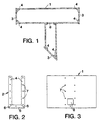
- Figure 1 is a cross-section through a sump and trough joined in the manner described in this invention.
- the cross-section is at a level showing the aperture providing for communication between the trough and the sump.
- Figure 2 is an elevation view of the end of the trough shown in Figure 1 before it is is joined to the sump.
- Figure 3 is a side elevation view of the sump in Figure 1 before the trough is attached.
- Figure 4 is a cross-sectional view of a similar trough and sump construction to that shown in Figure 1 with the difference that the sump was provided for apertures for two trough connections, one of which was closed by an end plate.
- Figure 1 shows a sump, 1, to which is attached a trough, 2.
- the open ends of the sump and trough are closed by end plates, 3.
- the end plates are attached by bolts, (not shown), to inwardly directed vertical tabs, 4, located at the ends of the vertical walls of the trough and sump and to inwardly directed horizontal tabs, 5, along the bases of the trough and sump.
- Reference to Figure 2 will indicate that the tabs are cut such that together two wall tabs and a base tab form a continuous flange when the contacting edges of the tabs are welded together along weld lines, 6. Similar flanges are provided at either end of the sump and at the opposite end of the trough.
- Figure 3 shows the side of the sump before the end of the trough shown in Figure 2 is attached thereto.
- An aperture, 8, in the wall of the sump is designed to provide communication with the trough when this is bolted in place using bolts inserted through bolt holes, 7.
- the sump was 39.3 cm deep and 16 cm in width and 28.2 cm long.
- the aperture communicating with the trough was 5 cm x 6.8 cm and the trough was 14.6 cm wide, 38.1 cm deep and, on account of the angled end had a greatest length of 54.4 cm and a shortest length of 34.45 cm.
- the steel used for both end caps, sump and trough was 16 gauge stainless steel. Since the objective is to evaluate the integrity of the jointing system, (that is whether significant amounts were lost as drips at the joint locations), the usual perforations in the trough and sump were absent. In other respects the materials and the joints were exactly as would be used in a commercial system.
- the flange was sprayed with glue and a gasket material was applied to the glued surface and a second layer of gasket material was glued on top of the first. Care was taken to ensure that adequate sealing of the gasket material joints was accomplished. A screwdriver was used to open holes in the gasket material to permit passage of the bolts.
- the flanges on the ends of the trough were bolted to the end plates using 1" x 3/8" bolts.
- the bolts at the bottom had 3/8" washers on both sides and all bolts were torqued to 14 ft.lbs and then re-checked.
- the bolts at the acute angle of the closed end of the trough were cut down to fit the space.
- the trough and sump were filled with water to saturate the gaskets and then the system was filled to a depth of 35.6 cm. After an hour the water level had dropped to 32.3 cm. This amounted to a loss rate of only 0.00083 gallons/minute/foot (10 ml/min/m) of joint. This is a very satisfactory performance for such a structure.
Landscapes
- Chemical & Material Sciences (AREA)
- Chemical Kinetics & Catalysis (AREA)
- Vaporization, Distillation, Condensation, Sublimation, And Cold Traps (AREA)
- Physical Or Chemical Processes And Apparatus (AREA)
- Bipolar Transistors (AREA)
- Amplifiers (AREA)
- Gasket Seals (AREA)
- Details Of Rigid Or Semi-Rigid Containers (AREA)
- Filling Or Discharging Of Gas Storage Vessels (AREA)
- Quick-Acting Or Multi-Walled Pipe Joints (AREA)
- Extraction Or Liquid Replacement (AREA)
Description
A...435 ml. B...400 ml. C...675 ml. D...590 ml. E...675 ml.
This gave a calculated leakage rate of 0.000825 gallons/minute/foot of joint.
Claims (2)
- A distribution trough (2) adapted to be joined to an element with a flat surface, said trough comprising opposed containment walls and a trough bottom joining said containment walls at their lower extremities in which at least one end of the trough is modified by the provision of an internal flange (4, 5) within the trough adapted to be bolted to the element to which the trough is to be joined and formed by the inward folding of the ends of the containment walls and bottom of the trough.
- A liquid distribution system which comprises a central sump (1) having walls and a bottom, said walls being provided with a number of apertures (8) therein, and a plurality of troughs (2) according to Claim 1 attached to walls of the sump so as to provide liquid flow paths from the sump to the troughs through said apertures in the sump walls.
Applications Claiming Priority (3)
| Application Number | Priority Date | Filing Date | Title |
|---|---|---|---|
| US39498695A | 1995-02-27 | 1995-02-27 | |
| PCT/US1996/001258 WO1996026778A1 (en) | 1995-02-27 | 1996-01-26 | Distributor trough junctions |
| US394986 | 1999-09-13 |
Publications (2)
| Publication Number | Publication Date |
|---|---|
| EP0812232A1 EP0812232A1 (en) | 1997-12-17 |
| EP0812232B1 true EP0812232B1 (en) | 2000-03-15 |
Family
ID=23561213
Family Applications (1)
| Application Number | Title | Priority Date | Filing Date |
|---|---|---|---|
| EP96905296A Expired - Lifetime EP0812232B1 (en) | 1995-02-27 | 1996-01-26 | Distributor trough junctions |
Country Status (12)
| Country | Link |
|---|---|
| US (1) | US5597655A (en) |
| EP (1) | EP0812232B1 (en) |
| JP (1) | JP3117999B2 (en) |
| KR (1) | KR100216487B1 (en) |
| CN (1) | CN1045898C (en) |
| AU (1) | AU684684B2 (en) |
| BR (1) | BR9606954A (en) |
| DE (1) | DE69607150T2 (en) |
| ES (1) | ES2146392T3 (en) |
| RU (1) | RU2131756C1 (en) |
| TW (1) | TW375674B (en) |
| WO (1) | WO1996026778A1 (en) |
Families Citing this family (3)
| Publication number | Priority date | Publication date | Assignee | Title |
|---|---|---|---|---|
| EP1153640B1 (en) * | 2000-05-08 | 2009-10-07 | Sulzer Chemtech AG | Container having a deflector for diverting a liquid jet |
| CA2338215C (en) | 2000-05-08 | 2004-09-14 | Sulzer Chemtech Ag | Guide member for a liquid jet to be deflected |
| US8175316B2 (en) | 2006-12-05 | 2012-05-08 | Sony Corporation | Ear speaker device |
Family Cites Families (8)
| Publication number | Priority date | Publication date | Assignee | Title |
|---|---|---|---|---|
| FR703029A (en) * | 1930-09-24 | 1931-04-22 | Watering device for absorption towers, washing towers and the like | |
| US2517998A (en) * | 1947-12-15 | 1950-08-08 | Jr Harry R Gilchrist | Apparatus for diffusing water in evaporation coolers |
| US2640619A (en) * | 1950-01-05 | 1953-06-02 | Schneiderman Eli | Fitting for electrical conduits |
| US3816225A (en) * | 1972-07-26 | 1974-06-11 | O Eckel | Acoustical panel assembly and method of forming it |
| US3758703A (en) * | 1972-08-16 | 1973-09-11 | Reliable Electric Co | Wire connector |
| CA1324571C (en) * | 1989-01-13 | 1993-11-23 | Koch (Cyprus) Limited | Double-deck distributor |
| US5051214A (en) * | 1989-01-13 | 1991-09-24 | Glitsch, Inc. | Double-deck distributor and method of liquid distribution |
| DE3902275A1 (en) * | 1989-01-26 | 1990-08-02 | Linde Ag | Liquid distributor |
-
1995
- 1995-10-17 US US08/544,288 patent/US5597655A/en not_active Expired - Fee Related
-
1996
- 1996-01-26 ES ES96905296T patent/ES2146392T3/en not_active Expired - Lifetime
- 1996-01-26 WO PCT/US1996/001258 patent/WO1996026778A1/en active IP Right Grant
- 1996-01-26 BR BR9606954A patent/BR9606954A/en not_active Application Discontinuation
- 1996-01-26 AU AU49102/96A patent/AU684684B2/en not_active Ceased
- 1996-01-26 JP JP08526258A patent/JP3117999B2/en not_active Expired - Fee Related
- 1996-01-26 KR KR1019970704586A patent/KR100216487B1/en not_active IP Right Cessation
- 1996-01-26 CN CN96192110A patent/CN1045898C/en not_active Expired - Fee Related
- 1996-01-26 RU RU97115812A patent/RU2131756C1/en active
- 1996-01-26 DE DE69607150T patent/DE69607150T2/en not_active Expired - Fee Related
- 1996-01-26 EP EP96905296A patent/EP0812232B1/en not_active Expired - Lifetime
- 1996-01-29 TW TW085101091A patent/TW375674B/en active
Also Published As
| Publication number | Publication date |
|---|---|
| RU2131756C1 (en) | 1999-06-20 |
| CN1175909A (en) | 1998-03-11 |
| AU4910296A (en) | 1996-09-18 |
| KR100216487B1 (en) | 1999-08-16 |
| AU684684B2 (en) | 1997-12-18 |
| ES2146392T3 (en) | 2000-08-01 |
| TW375674B (en) | 1999-12-01 |
| WO1996026778A1 (en) | 1996-09-06 |
| JP3117999B2 (en) | 2000-12-18 |
| JPH10505787A (en) | 1998-06-09 |
| KR987000885A (en) | 1998-04-30 |
| DE69607150D1 (en) | 2000-04-20 |
| DE69607150T2 (en) | 2000-11-16 |
| EP0812232A1 (en) | 1997-12-17 |
| US5597655A (en) | 1997-01-28 |
| MX9706486A (en) | 1997-11-29 |
| CN1045898C (en) | 1999-10-27 |
| BR9606954A (en) | 1997-10-28 |
Similar Documents
| Publication | Publication Date | Title |
|---|---|---|
| US6431387B2 (en) | Flat-bottomed tank and method for fitting it with a leak-proof coating | |
| JP7241777B2 (en) | Insulated sealed tank | |
| US4751945A (en) | Dual containment channel for fluids | |
| US7240804B2 (en) | Full contact floating roof | |
| KR102502222B1 (en) | Sealing wall with reinforced corrugated membrane | |
| EP0812232B1 (en) | Distributor trough junctions | |
| EP1567252B1 (en) | Bolted collector for vapor liquid contacting vessel | |
| CA2208747C (en) | Distributor trough junctions | |
| US8499394B1 (en) | Waterproof expansion joint | |
| MXPA97006486A (en) | Joints for artesa distribuid | |
| US2220186A (en) | Tank construction | |
| US5474207A (en) | Liquid storage tank with glass reinforced plastic tie rods | |
| US6922956B2 (en) | Floating cover | |
| CA2387587A1 (en) | Leak-resistant lining for tanks and a method for equipping tanks therewith | |
| EP0147184B1 (en) | Flat glass sight gauge | |
| KR101875328B1 (en) | Sealed and thermally insulating tank, ship comprising the tank, process of loading or unloading of the ship, and transfer system comprising the ship | |
| US2291132A (en) | Packing member for bolted tanks | |
| JP2543121Y2 (en) | Slot Shape and Longe Penetration Structure in Oil-Watertight Bulkhead of Ship | |
| US20240026674A1 (en) | Modular well cellar | |
| IT202200001406U1 (en) | Connection system for containment tanks made in several parts for fuel tanks, with guaranteed resistance to infiltration and spillage | |
| HU226440B1 (en) | Collecting vessel | |
| RU2380U1 (en) | OIL RESERVOIR COVER FOR OIL PRODUCTS | |
| JPS62174624A (en) | Field inspecting method for large-sized tower tank, or the like | |
| JPH07293943A (en) | Built-up water tank made of steel plate | |
| JPH0699942B2 (en) | Anticorrosion cover installation method |
Legal Events
| Date | Code | Title | Description |
|---|---|---|---|
| PUAI | Public reference made under article 153(3) epc to a published international application that has entered the european phase |
Free format text: ORIGINAL CODE: 0009012 |
|
| 17P | Request for examination filed |
Effective date: 19970929 |
|
| AK | Designated contracting states |
Kind code of ref document: A1 Designated state(s): DE ES FR GB IT NL SE |
|
| GRAG | Despatch of communication of intention to grant |
Free format text: ORIGINAL CODE: EPIDOS AGRA |
|
| 17Q | First examination report despatched |
Effective date: 19990414 |
|
| GRAG | Despatch of communication of intention to grant |
Free format text: ORIGINAL CODE: EPIDOS AGRA |
|
| GRAH | Despatch of communication of intention to grant a patent |
Free format text: ORIGINAL CODE: EPIDOS IGRA |
|
| GRAH | Despatch of communication of intention to grant a patent |
Free format text: ORIGINAL CODE: EPIDOS IGRA |
|
| GRAA | (expected) grant |
Free format text: ORIGINAL CODE: 0009210 |
|
| AK | Designated contracting states |
Kind code of ref document: B1 Designated state(s): DE ES FR GB IT NL SE |
|
| REF | Corresponds to: |
Ref document number: 69607150 Country of ref document: DE Date of ref document: 20000420 |
|
| ITF | It: translation for a ep patent filed |
Owner name: DOTT. FRANCO CICOGNA |
|
| ET | Fr: translation filed | ||
| REG | Reference to a national code |
Ref country code: ES Ref legal event code: FG2A Ref document number: 2146392 Country of ref document: ES Kind code of ref document: T3 |
|
| PLBE | No opposition filed within time limit |
Free format text: ORIGINAL CODE: 0009261 |
|
| STAA | Information on the status of an ep patent application or granted ep patent |
Free format text: STATUS: NO OPPOSITION FILED WITHIN TIME LIMIT |
|
| PG25 | Lapsed in a contracting state [announced via postgrant information from national office to epo] |
Ref country code: GB Free format text: LAPSE BECAUSE OF NON-PAYMENT OF DUE FEES Effective date: 20010126 |
|
| PG25 | Lapsed in a contracting state [announced via postgrant information from national office to epo] |
Ref country code: SE Free format text: LAPSE BECAUSE OF NON-PAYMENT OF DUE FEES Effective date: 20010127 Ref country code: ES Free format text: LAPSE BECAUSE OF NON-PAYMENT OF DUE FEES Effective date: 20010127 |
|
| 26N | No opposition filed | ||
| PG25 | Lapsed in a contracting state [announced via postgrant information from national office to epo] |
Ref country code: NL Free format text: LAPSE BECAUSE OF NON-PAYMENT OF DUE FEES Effective date: 20010801 |
|
| EUG | Se: european patent has lapsed |
Ref document number: 96905296.8 |
|
| GBPC | Gb: european patent ceased through non-payment of renewal fee |
Effective date: 20010126 |
|
| NLV4 | Nl: lapsed or anulled due to non-payment of the annual fee |
Effective date: 20010801 |
|
| PG25 | Lapsed in a contracting state [announced via postgrant information from national office to epo] |
Ref country code: DE Free format text: LAPSE BECAUSE OF NON-PAYMENT OF DUE FEES Effective date: 20011101 |
|
| PG25 | Lapsed in a contracting state [announced via postgrant information from national office to epo] |
Ref country code: FR Free format text: LAPSE BECAUSE OF NON-PAYMENT OF DUE FEES Effective date: 20020329 |
|
| REG | Reference to a national code |
Ref country code: FR Ref legal event code: ST |
|
| REG | Reference to a national code |
Ref country code: ES Ref legal event code: FD2A Effective date: 20021016 |
|
| PG25 | Lapsed in a contracting state [announced via postgrant information from national office to epo] |
Ref country code: IT Free format text: LAPSE BECAUSE OF NON-PAYMENT OF DUE FEES;WARNING: LAPSES OF ITALIAN PATENTS WITH EFFECTIVE DATE BEFORE 2007 MAY HAVE OCCURRED AT ANY TIME BEFORE 2007. THE CORRECT EFFECTIVE DATE MAY BE DIFFERENT FROM THE ONE RECORDED. Effective date: 20050126 |
|
| PG25 | Lapsed in a contracting state [announced via postgrant information from national office to epo] |
Ref country code: FR Free format text: LAPSE BECAUSE OF NON-PAYMENT OF DUE FEES Effective date: 20010131 |