EP0811559A1 - Récipient à distribution par le bas avec système de reprise d'air - Google Patents
Récipient à distribution par le bas avec système de reprise d'air Download PDFInfo
- Publication number
- EP0811559A1 EP0811559A1 EP97303359A EP97303359A EP0811559A1 EP 0811559 A1 EP0811559 A1 EP 0811559A1 EP 97303359 A EP97303359 A EP 97303359A EP 97303359 A EP97303359 A EP 97303359A EP 0811559 A1 EP0811559 A1 EP 0811559A1
- Authority
- EP
- European Patent Office
- Prior art keywords
- container
- package according
- dispensing package
- head
- dispensing
- Prior art date
- Legal status (The legal status is an assumption and is not a legal conclusion. Google has not performed a legal analysis and makes no representation as to the accuracy of the status listed.)
- Withdrawn
Links
Images


Classifications
-
- B—PERFORMING OPERATIONS; TRANSPORTING
- B65—CONVEYING; PACKING; STORING; HANDLING THIN OR FILAMENTARY MATERIAL
- B65D—CONTAINERS FOR STORAGE OR TRANSPORT OF ARTICLES OR MATERIALS, e.g. BAGS, BARRELS, BOTTLES, BOXES, CANS, CARTONS, CRATES, DRUMS, JARS, TANKS, HOPPERS, FORWARDING CONTAINERS; ACCESSORIES, CLOSURES, OR FITTINGS THEREFOR; PACKAGING ELEMENTS; PACKAGES
- B65D51/00—Closures not otherwise provided for
- B65D51/16—Closures not otherwise provided for with means for venting air or gas
- B65D51/1633—Closures not otherwise provided for with means for venting air or gas whereby venting occurs by automatic opening of the closure, container or other element
- B65D51/1644—Closures not otherwise provided for with means for venting air or gas whereby venting occurs by automatic opening of the closure, container or other element the element being a valve
- B65D51/165—Closures not otherwise provided for with means for venting air or gas whereby venting occurs by automatic opening of the closure, container or other element the element being a valve formed by a slit or narrow opening
-
- B—PERFORMING OPERATIONS; TRANSPORTING
- B65—CONVEYING; PACKING; STORING; HANDLING THIN OR FILAMENTARY MATERIAL
- B65D—CONTAINERS FOR STORAGE OR TRANSPORT OF ARTICLES OR MATERIALS, e.g. BAGS, BARRELS, BOTTLES, BOXES, CANS, CARTONS, CRATES, DRUMS, JARS, TANKS, HOPPERS, FORWARDING CONTAINERS; ACCESSORIES, CLOSURES, OR FITTINGS THEREFOR; PACKAGING ELEMENTS; PACKAGES
- B65D1/00—Containers having bodies formed in one piece, e.g. by casting metallic material, by moulding plastics, by blowing vitreous material, by throwing ceramic material, by moulding pulped fibrous material, by deep-drawing operations performed on sheet material
- B65D1/32—Containers adapted to be temporarily deformed by external pressure to expel contents
-
- B—PERFORMING OPERATIONS; TRANSPORTING
- B65—CONVEYING; PACKING; STORING; HANDLING THIN OR FILAMENTARY MATERIAL
- B65D—CONTAINERS FOR STORAGE OR TRANSPORT OF ARTICLES OR MATERIALS, e.g. BAGS, BARRELS, BOTTLES, BOXES, CANS, CARTONS, CRATES, DRUMS, JARS, TANKS, HOPPERS, FORWARDING CONTAINERS; ACCESSORIES, CLOSURES, OR FITTINGS THEREFOR; PACKAGING ELEMENTS; PACKAGES
- B65D47/00—Closures with filling and discharging, or with discharging, devices
- B65D47/04—Closures with discharging devices other than pumps
- B65D47/20—Closures with discharging devices other than pumps comprising hand-operated members for controlling discharge
- B65D47/2018—Closures with discharging devices other than pumps comprising hand-operated members for controlling discharge comprising a valve or like element which is opened or closed by deformation of the container or closure
- B65D47/2031—Closures with discharging devices other than pumps comprising hand-operated members for controlling discharge comprising a valve or like element which is opened or closed by deformation of the container or closure the element being formed by a slit, narrow opening or constrictable spout, the size of the outlet passage being able to be varied by increasing or decreasing the pressure
Definitions
- the invention relates to inverted dispensing packages fitted with vent mechanisms for improving the speed of air pressure equalization.
- inverted packaging refers to packaging whose discharge opening is on the same end of the container intended to standingly engage support surfaces upon which the package normally rests. Colloquially the arrangement is known as bottom delivery packaging.
- Bottom delivery packages with self-sealing valves for storing and dispensing fluid materials have been commercially employed as packaging for shampoos, conditioners, soaps and detergents.
- Use of a self-sealing valve eliminates the need to operate a removable closure when dispensing the product.
- the self-sealing valve has a closed position for preventing any discharge of fluid through the valve when not in use, and an open position to dispense fluid through the valve upon application of manual squeezing forces.
- Air equalization problems are particularly prevalent with self-sealing valves such as the slitted silicone rubber type reported in U.S. Patent 5,033,655, U.S. Patent 5,213,236 and U.S. Patent 5,339,995, all to Brown et al. of Liquid Molding Systems, Inc. Similar difficulties are associated with self-sealing dispensing valves in containers disclosed by U.S. Patent 4,728,006 (Drobish et al.) designed for shampoos, conditioners and other hair care products.
- U.S. Patent 5,431,290 in the context of baby bottles has achieved improved flow through use of a one-way air valve including a central diverging passage defined by opposed converging sidewalls which have a tiny slit elongated along the apex portion of the converging sidewalls in an annular base sized for attachment to the open end of the baby bottle.
- the valve is concavely mounted onto the bottle to avoid breakage and to prevent leakage of the contents.
- Still another object of the present invention is to provide an inverted dispensing package with a venting mechanism that permits significant reduction in container weight without a lose of package performance.
- a dispensing package for a fluid product includes:
- a particularly useful flow control valve for purposes of this invention is a silicone rubber formed with a resiliently flexible connector sleeve capped with a head that shifts outwardly in a manner which causes the sleeve to double over and extend rollingly when pressure within the container rises above a pre-determined amount.
- Sliced across the head are at least one slit, preferably at least a pair of slits.
- the preferred embodiment orients the first and second slits in a mutually intersecting relationship.
- U.S. Patent 5,339,995 assigned to Liquid Molding Systems, Inc. discloses a preferred valve of the aforementioned construction.
- the package may further include an opening along the first end adjacent the flow control valve.
- a hollow dip tube having first and second termini at opposite ends is arranged within the container, the first terminus being anchored over the open end.
- the hollow dip tube projects inwardly toward the second end of the container.
- a one-way venting mechanism is fitted onto the second terminus of the dip tube.
- Venting mechanisms of the present invention may include an elastomeric head having a slit with lips closed together when air pressure inside is equal to ambient pressure outside. When ambient air pressure outside the container is greater than that inside, the lips will be forced open.
- the venting mechanism includes a plug seal fitment arranged at the second end of the container.
- an elastomeric rubber member Within the container is held an elastomeric rubber member.
- This rubber member has a round conical segment which tapers outwardly to a thinner width terminating in a edge sealingly contacting an inner wall of the plug seal fitment.
- the round conical segment desirably is sufficiently resilient to flex downwardly toward the first end of the container upon creation of a reduced pressure therewithin to admit equalizing ambient air pressure into the container.
- an elastomeric head is seated within walls of the container and includes an anchor portion, a body portion and a head portion.
- the head portion is directed and tapers toward an interior of the container, terminating in an end having a slit which includes lips held sealingly together under equal pressurization but flexibly separable to allow air passage under unequal pressurization.
- the anchor portion is a flange whose underside abuts an outer wall of the container.
- the container have walls squeezably deformable upon application of hand pressure. Pressure forces dispensing of the container contents. These walls can rapidly recover their storage shape after removal of the hand pressure.
- the dispensing package includes a container 2 storing a fluid product 4 , a flow control valve 6 and a one-way venting mechanism 8 .
- the container has a first and second end 10 , 12 opposite one another.
- a discharge opening 14 is located at the first end and configured to standingly engage support surfaces upon which the package normally rests.
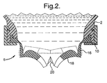
- FIG. 2 A preferred embodiment of the flow control valve 6 is shown in Fig. 2.
- a silicone rubber is formed into a resiliently flexible connector sleeve 16 capped with a head 18 that shifts outwardly in a manner which causes the sleeve to double over and extend rollingly when pressure within the container rises above a predetermined amount.
- the head includes first and second slits 20 oriented in a mutually intersecting relationship.
- the package further includes an opening 22 along the first end 10 of the container adjacent the flow control valve 6 .
- a hollow dip tube 24 within the container has a first and second terminus 26 , 28 at opposite ends.
- the first terminus 26 is anchored over the opening 22 and projects inwardly toward the second end 12 of the container.
- the second terminus of the dip tube is attached to the one-way venting mechanism which is an elastomeric head 30 having a slit 32 with lips closed together when air pressure inside is equal to ambient pressure outside the container and with lips forced open when ambient pressure outside is greater than that inside the container.
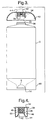
- Fig. 3 illustrates a second embodiment of the dispensing package.
- the venting mechanism includes a plug seal fitment 34 arranged at the second end of the container. Within the plug seal fitment is held an elastomeric rubber member 36 . Fitment 34 seats over neck 38 , the latter having an air inlet 40 .
- Fig. 4 illustrates the elastomeric rubber member 36 in greater detail.
- This member has a round conical segment 42 which tapers outwardly to a thinner width terminating in an edge 44 sealingly contacting an inner wall 46 of the plug seal fitment 34 .
- Round conical segment 42 is sufficiently resilient to flex downwardly toward the first end 10 of the container upon creation of a reduced pressure therewithin to thereby admit equalizing ambient air pressure into the container.
- a central gripping post 48 projects downward from the fitment.
- the round conical segment embraces post 48 through a central recess 50 . Vent holes 52 allow transfer of air through the fitment.
- Fig. 5 illustrates a third embodiment of the present invention.
- An elastomeric head 54 is seated within the walls 56 of container 2 .
- the elastomeric head includes an anchor portion 58 , a body portion 60 and a head portion 62 .
- the head portion is directed and tapers toward an interior 64 of the container, terminating in an end having a slit 66 .
- the slit includes lips held sealingly together under equal pressurization but flexibly separable to allow air passage under unequal pressurization.
- the anchor portion is constructed as a flange whose underside 68 abuts the outer wall 56 of the container.
Landscapes
- Engineering & Computer Science (AREA)
- Mechanical Engineering (AREA)
- Ceramic Engineering (AREA)
- Closures For Containers (AREA)
- Containers And Packaging Bodies Having A Special Means To Remove Contents (AREA)
- Check Valves (AREA)
- Containers Having Bodies Formed In One Piece (AREA)
Applications Claiming Priority (2)
| Application Number | Priority Date | Filing Date | Title |
|---|---|---|---|
| US65799196A | 1996-06-04 | 1996-06-04 | |
| US657991 | 2000-09-08 |
Publications (1)
| Publication Number | Publication Date |
|---|---|
| EP0811559A1 true EP0811559A1 (fr) | 1997-12-10 |
Family
ID=24639461
Family Applications (1)
| Application Number | Title | Priority Date | Filing Date |
|---|---|---|---|
| EP97303359A Withdrawn EP0811559A1 (fr) | 1996-06-04 | 1997-05-16 | Récipient à distribution par le bas avec système de reprise d'air |
Country Status (5)
| Country | Link |
|---|---|
| EP (1) | EP0811559A1 (fr) |
| JP (1) | JPH10114355A (fr) |
| BR (1) | BR9703446A (fr) |
| CA (1) | CA2205816A1 (fr) |
| ZA (1) | ZA974670B (fr) |
Cited By (3)
| Publication number | Priority date | Publication date | Assignee | Title |
|---|---|---|---|---|
| DE102010006533A1 (de) * | 2010-02-01 | 2011-08-04 | Nikic, Ivan, 55546 | Spender mit Bestreicher für Marmelade, Konfitüre und andere Massen |
| WO2015069857A1 (fr) | 2013-11-06 | 2015-05-14 | The Procter & Gamble Company | Contenants flexibles dotés de systèmes d'évents |
| WO2016057623A1 (fr) | 2014-10-07 | 2016-04-14 | The Procter & Gamble Company | Procédé de prétraitement d'articles à laver dans un lave-vaisselle |
Families Citing this family (3)
| Publication number | Priority date | Publication date | Assignee | Title |
|---|---|---|---|---|
| EP2531415A4 (fr) | 2010-02-02 | 2014-01-22 | Diversey Inc | Récipient et procédé de distribution de liquide |
| WO2011112835A2 (fr) | 2010-03-11 | 2011-09-15 | Diversey, Inc. | Appareil à tube de mise à l'air libre et procédé |
| US11613417B2 (en) * | 2021-02-19 | 2023-03-28 | Winpak Ltd. | Container for foodstuff storage and dispensing |
Citations (5)
| Publication number | Priority date | Publication date | Assignee | Title |
|---|---|---|---|---|
| US4087024A (en) * | 1976-02-27 | 1978-05-02 | Graber-Rogg, Inc. | Fluid dispenser |
| EP0500249A1 (fr) * | 1991-02-19 | 1992-08-26 | Pilkington Barnes Hind, Inc. | Distributeur |
| US5213236A (en) * | 1991-12-06 | 1993-05-25 | Liquid Molding Systems, Inc. | Dispensing valve for packaging |
| EP0659365A1 (fr) * | 1993-12-22 | 1995-06-28 | L'oreal | Dispositif pour préparer de manière dosée, et distribuer un produit cosmétique |
| US5431290A (en) * | 1992-03-24 | 1995-07-11 | Vinciguerra; Mark T. | Baby bottle for improved flow |
-
1997
- 1997-05-16 EP EP97303359A patent/EP0811559A1/fr not_active Withdrawn
- 1997-05-22 CA CA002205816A patent/CA2205816A1/fr not_active Abandoned
- 1997-05-28 ZA ZA974670A patent/ZA974670B/xx unknown
- 1997-06-04 JP JP14670097A patent/JPH10114355A/ja active Pending
- 1997-06-04 BR BR9703446A patent/BR9703446A/pt not_active Application Discontinuation
Patent Citations (5)
| Publication number | Priority date | Publication date | Assignee | Title |
|---|---|---|---|---|
| US4087024A (en) * | 1976-02-27 | 1978-05-02 | Graber-Rogg, Inc. | Fluid dispenser |
| EP0500249A1 (fr) * | 1991-02-19 | 1992-08-26 | Pilkington Barnes Hind, Inc. | Distributeur |
| US5213236A (en) * | 1991-12-06 | 1993-05-25 | Liquid Molding Systems, Inc. | Dispensing valve for packaging |
| US5431290A (en) * | 1992-03-24 | 1995-07-11 | Vinciguerra; Mark T. | Baby bottle for improved flow |
| EP0659365A1 (fr) * | 1993-12-22 | 1995-06-28 | L'oreal | Dispositif pour préparer de manière dosée, et distribuer un produit cosmétique |
Cited By (3)
| Publication number | Priority date | Publication date | Assignee | Title |
|---|---|---|---|---|
| DE102010006533A1 (de) * | 2010-02-01 | 2011-08-04 | Nikic, Ivan, 55546 | Spender mit Bestreicher für Marmelade, Konfitüre und andere Massen |
| WO2015069857A1 (fr) | 2013-11-06 | 2015-05-14 | The Procter & Gamble Company | Contenants flexibles dotés de systèmes d'évents |
| WO2016057623A1 (fr) | 2014-10-07 | 2016-04-14 | The Procter & Gamble Company | Procédé de prétraitement d'articles à laver dans un lave-vaisselle |
Also Published As
| Publication number | Publication date |
|---|---|
| ZA974670B (en) | 1998-11-30 |
| CA2205816A1 (fr) | 1997-12-04 |
| JPH10114355A (ja) | 1998-05-06 |
| BR9703446A (pt) | 1998-10-27 |
Similar Documents
| Publication | Publication Date | Title |
|---|---|---|
| US6951295B1 (en) | Flow control element and dispensing structure incorporating same | |
| FI87173B (fi) | Foerpackning foer lagring och utmatning av fluider. | |
| AU766739B2 (en) | One-piece dispensing system and method for making same | |
| CA2297211C (fr) | Soupapes pour recipients de conditionnement | |
| EP1216932B1 (fr) | Clapet de distribution pour récipient | |
| US4728006A (en) | Flexible container including self-sealing dispensing valve to provide automatic shut-off and leak resistant inverted storage | |
| US6749092B2 (en) | Deformable dispensing valve | |
| EP0479938B1 (fr) | Dispositif de distribution de substances fluides | |
| US5819984A (en) | Package with storage and plug retention features | |
| EP1924509B1 (fr) | Fermeture resistant aux debordements | |
| EP0405472A1 (fr) | Fermeture de distribution souple | |
| BRPI0907849B1 (pt) | Sistema de montagem para montar uma válvula para acomodar fluxo de uma substância proveniente de um fornecimento da substância | |
| ITTO980115U1 (it) | Chiusura di erogazione provvista di una valvola comandata a pressione. | |
| USH2027H1 (en) | Flexible slit valve | |
| US3232499A (en) | Molded bottle caps with integral valve structure | |
| US4884707A (en) | Water bottle cap | |
| EP0811559A1 (fr) | Récipient à distribution par le bas avec système de reprise d'air | |
| CA2156513A1 (fr) | Fermeture comportant un capuchon bibloc coulissant d'obturation du conduit de distribution | |
| GB2330577A (en) | Dispensing valve with a slitted diaphragm and retention ring | |
| AU608663B2 (en) | Tap assembly | |
| US4508246A (en) | Check means for a water dispenser | |
| AU714697B3 (en) | One-piece dispensing system and method for making same |
Legal Events
| Date | Code | Title | Description |
|---|---|---|---|
| PUAI | Public reference made under article 153(3) epc to a published international application that has entered the european phase |
Free format text: ORIGINAL CODE: 0009012 |
|
| AK | Designated contracting states |
Kind code of ref document: A1 Designated state(s): DE ES FR GB IT |
|
| 17P | Request for examination filed |
Effective date: 19980123 |
|
| 17Q | First examination report despatched |
Effective date: 20010910 |
|
| STAA | Information on the status of an ep patent application or granted ep patent |
Free format text: STATUS: THE APPLICATION IS DEEMED TO BE WITHDRAWN |
|
| 18D | Application deemed to be withdrawn |
Effective date: 20020122 |