EP0810592A1 - Process and device for bonding discs to one another - Google Patents
Process and device for bonding discs to one another Download PDFInfo
- Publication number
- EP0810592A1 EP0810592A1 EP97109113A EP97109113A EP0810592A1 EP 0810592 A1 EP0810592 A1 EP 0810592A1 EP 97109113 A EP97109113 A EP 97109113A EP 97109113 A EP97109113 A EP 97109113A EP 0810592 A1 EP0810592 A1 EP 0810592A1
- Authority
- EP
- European Patent Office
- Prior art keywords
- light
- discs
- radiation
- disc substrates
- bonding
- Prior art date
- Legal status (The legal status is an assumption and is not a legal conclusion. Google has not performed a legal analysis and makes no representation as to the accuracy of the status listed.)
- Granted
Links
- 238000000034 method Methods 0.000 title claims description 9
- 230000005855 radiation Effects 0.000 claims abstract description 76
- 239000000758 substrate Substances 0.000 claims abstract description 50
- 238000001816 cooling Methods 0.000 claims abstract description 24
- 229910052782 aluminium Inorganic materials 0.000 claims abstract description 22
- XAGFODPZIPBFFR-UHFFFAOYSA-N aluminium Chemical compound [Al] XAGFODPZIPBFFR-UHFFFAOYSA-N 0.000 claims abstract description 22
- 230000003287 optical effect Effects 0.000 claims abstract description 5
- VYPSYNLAJGMNEJ-UHFFFAOYSA-N Silicium dioxide Chemical compound O=[Si]=O VYPSYNLAJGMNEJ-UHFFFAOYSA-N 0.000 claims description 36
- 229910052724 xenon Inorganic materials 0.000 claims description 12
- FHNFHKCVQCLJFQ-UHFFFAOYSA-N xenon atom Chemical compound [Xe] FHNFHKCVQCLJFQ-UHFFFAOYSA-N 0.000 claims description 12
- 239000000203 mixture Substances 0.000 claims description 4
- 230000001678 irradiating effect Effects 0.000 claims description 2
- 239000007767 bonding agent Substances 0.000 claims 5
- 238000002844 melting Methods 0.000 abstract description 8
- 230000008018 melting Effects 0.000 abstract description 8
- 239000004568 cement Substances 0.000 abstract description 3
- 229920005989 resin Polymers 0.000 description 19
- 239000011347 resin Substances 0.000 description 19
- 239000003990 capacitor Substances 0.000 description 12
- 229920000515 polycarbonate Polymers 0.000 description 9
- 239000004417 polycarbonate Substances 0.000 description 9
- 230000001070 adhesive effect Effects 0.000 description 8
- 239000000853 adhesive Substances 0.000 description 7
- 239000000155 melt Substances 0.000 description 6
- 230000000694 effects Effects 0.000 description 5
- 238000005259 measurement Methods 0.000 description 5
- 230000001681 protective effect Effects 0.000 description 5
- 238000002834 transmittance Methods 0.000 description 5
- 230000005540 biological transmission Effects 0.000 description 4
- 238000010438 heat treatment Methods 0.000 description 4
- 239000000463 material Substances 0.000 description 4
- 230000007423 decrease Effects 0.000 description 3
- 230000031700 light absorption Effects 0.000 description 3
- 238000004904 shortening Methods 0.000 description 3
- 238000009281 ultraviolet germicidal irradiation Methods 0.000 description 3
- PXHVJJICTQNCMI-UHFFFAOYSA-N Nickel Chemical compound [Ni] PXHVJJICTQNCMI-UHFFFAOYSA-N 0.000 description 2
- NIXOWILDQLNWCW-UHFFFAOYSA-N acrylic acid group Chemical group C(C=C)(=O)O NIXOWILDQLNWCW-UHFFFAOYSA-N 0.000 description 2
- 230000002411 adverse Effects 0.000 description 2
- 238000009529 body temperature measurement Methods 0.000 description 2
- 230000006866 deterioration Effects 0.000 description 2
- 239000012535 impurity Substances 0.000 description 2
- 229920000098 polyolefin Polymers 0.000 description 2
- 230000002238 attenuated effect Effects 0.000 description 1
- 239000005388 borosilicate glass Substances 0.000 description 1
- 238000010276 construction Methods 0.000 description 1
- 239000002826 coolant Substances 0.000 description 1
- 239000011521 glass Substances 0.000 description 1
- PCHJSUWPFVWCPO-UHFFFAOYSA-N gold Chemical compound [Au] PCHJSUWPFVWCPO-UHFFFAOYSA-N 0.000 description 1
- 239000010931 gold Substances 0.000 description 1
- 229910052737 gold Inorganic materials 0.000 description 1
- 238000005286 illumination Methods 0.000 description 1
- QSHDDOUJBYECFT-UHFFFAOYSA-N mercury Chemical compound [Hg] QSHDDOUJBYECFT-UHFFFAOYSA-N 0.000 description 1
- 229910052753 mercury Inorganic materials 0.000 description 1
- 229910001507 metal halide Inorganic materials 0.000 description 1
- 150000005309 metal halides Chemical class 0.000 description 1
- 229910052759 nickel Inorganic materials 0.000 description 1
- 238000004528 spin coating Methods 0.000 description 1
- 230000001360 synchronised effect Effects 0.000 description 1
- 229920005992 thermoplastic resin Polymers 0.000 description 1
- 229910052720 vanadium Inorganic materials 0.000 description 1
Images


Classifications
-
- G—PHYSICS
- G11—INFORMATION STORAGE
- G11B—INFORMATION STORAGE BASED ON RELATIVE MOVEMENT BETWEEN RECORD CARRIER AND TRANSDUCER
- G11B7/00—Recording or reproducing by optical means, e.g. recording using a thermal beam of optical radiation by modifying optical properties or the physical structure, reproducing using an optical beam at lower power by sensing optical properties; Record carriers therefor
- G11B7/24—Record carriers characterised by shape, structure or physical properties, or by the selection of the material
- G11B7/26—Apparatus or processes specially adapted for the manufacture of record carriers
-
- B—PERFORMING OPERATIONS; TRANSPORTING
- B01—PHYSICAL OR CHEMICAL PROCESSES OR APPARATUS IN GENERAL
- B01J—CHEMICAL OR PHYSICAL PROCESSES, e.g. CATALYSIS OR COLLOID CHEMISTRY; THEIR RELEVANT APPARATUS
- B01J19/00—Chemical, physical or physico-chemical processes in general; Their relevant apparatus
- B01J19/08—Processes employing the direct application of electric or wave energy, or particle radiation; Apparatus therefor
- B01J19/12—Processes employing the direct application of electric or wave energy, or particle radiation; Apparatus therefor employing electromagnetic waves
- B01J19/122—Incoherent waves
- B01J19/123—Ultraviolet light
-
- B—PERFORMING OPERATIONS; TRANSPORTING
- B29—WORKING OF PLASTICS; WORKING OF SUBSTANCES IN A PLASTIC STATE IN GENERAL
- B29C—SHAPING OR JOINING OF PLASTICS; SHAPING OF MATERIAL IN A PLASTIC STATE, NOT OTHERWISE PROVIDED FOR; AFTER-TREATMENT OF THE SHAPED PRODUCTS, e.g. REPAIRING
- B29C65/00—Joining or sealing of preformed parts, e.g. welding of plastics materials; Apparatus therefor
- B29C65/02—Joining or sealing of preformed parts, e.g. welding of plastics materials; Apparatus therefor by heating, with or without pressure
- B29C65/14—Joining or sealing of preformed parts, e.g. welding of plastics materials; Apparatus therefor by heating, with or without pressure using wave energy, i.e. electromagnetic radiation, or particle radiation
- B29C65/1403—Joining or sealing of preformed parts, e.g. welding of plastics materials; Apparatus therefor by heating, with or without pressure using wave energy, i.e. electromagnetic radiation, or particle radiation characterised by the type of electromagnetic or particle radiation
- B29C65/1406—Ultraviolet [UV] radiation
-
- B—PERFORMING OPERATIONS; TRANSPORTING
- B29—WORKING OF PLASTICS; WORKING OF SUBSTANCES IN A PLASTIC STATE IN GENERAL
- B29C—SHAPING OR JOINING OF PLASTICS; SHAPING OF MATERIAL IN A PLASTIC STATE, NOT OTHERWISE PROVIDED FOR; AFTER-TREATMENT OF THE SHAPED PRODUCTS, e.g. REPAIRING
- B29C65/00—Joining or sealing of preformed parts, e.g. welding of plastics materials; Apparatus therefor
- B29C65/02—Joining or sealing of preformed parts, e.g. welding of plastics materials; Apparatus therefor by heating, with or without pressure
- B29C65/14—Joining or sealing of preformed parts, e.g. welding of plastics materials; Apparatus therefor by heating, with or without pressure using wave energy, i.e. electromagnetic radiation, or particle radiation
- B29C65/1429—Joining or sealing of preformed parts, e.g. welding of plastics materials; Apparatus therefor by heating, with or without pressure using wave energy, i.e. electromagnetic radiation, or particle radiation characterised by the way of heating the interface
- B29C65/1435—Joining or sealing of preformed parts, e.g. welding of plastics materials; Apparatus therefor by heating, with or without pressure using wave energy, i.e. electromagnetic radiation, or particle radiation characterised by the way of heating the interface at least passing through one of the parts to be joined, i.e. transmission welding
-
- B—PERFORMING OPERATIONS; TRANSPORTING
- B29—WORKING OF PLASTICS; WORKING OF SUBSTANCES IN A PLASTIC STATE IN GENERAL
- B29C—SHAPING OR JOINING OF PLASTICS; SHAPING OF MATERIAL IN A PLASTIC STATE, NOT OTHERWISE PROVIDED FOR; AFTER-TREATMENT OF THE SHAPED PRODUCTS, e.g. REPAIRING
- B29C65/00—Joining or sealing of preformed parts, e.g. welding of plastics materials; Apparatus therefor
- B29C65/02—Joining or sealing of preformed parts, e.g. welding of plastics materials; Apparatus therefor by heating, with or without pressure
- B29C65/14—Joining or sealing of preformed parts, e.g. welding of plastics materials; Apparatus therefor by heating, with or without pressure using wave energy, i.e. electromagnetic radiation, or particle radiation
- B29C65/1429—Joining or sealing of preformed parts, e.g. welding of plastics materials; Apparatus therefor by heating, with or without pressure using wave energy, i.e. electromagnetic radiation, or particle radiation characterised by the way of heating the interface
- B29C65/1445—Joining or sealing of preformed parts, e.g. welding of plastics materials; Apparatus therefor by heating, with or without pressure using wave energy, i.e. electromagnetic radiation, or particle radiation characterised by the way of heating the interface heating both sides of the joint
-
- B—PERFORMING OPERATIONS; TRANSPORTING
- B29—WORKING OF PLASTICS; WORKING OF SUBSTANCES IN A PLASTIC STATE IN GENERAL
- B29C—SHAPING OR JOINING OF PLASTICS; SHAPING OF MATERIAL IN A PLASTIC STATE, NOT OTHERWISE PROVIDED FOR; AFTER-TREATMENT OF THE SHAPED PRODUCTS, e.g. REPAIRING
- B29C65/00—Joining or sealing of preformed parts, e.g. welding of plastics materials; Apparatus therefor
- B29C65/02—Joining or sealing of preformed parts, e.g. welding of plastics materials; Apparatus therefor by heating, with or without pressure
- B29C65/14—Joining or sealing of preformed parts, e.g. welding of plastics materials; Apparatus therefor by heating, with or without pressure using wave energy, i.e. electromagnetic radiation, or particle radiation
- B29C65/1429—Joining or sealing of preformed parts, e.g. welding of plastics materials; Apparatus therefor by heating, with or without pressure using wave energy, i.e. electromagnetic radiation, or particle radiation characterised by the way of heating the interface
- B29C65/1464—Joining or sealing of preformed parts, e.g. welding of plastics materials; Apparatus therefor by heating, with or without pressure using wave energy, i.e. electromagnetic radiation, or particle radiation characterised by the way of heating the interface making use of several radiators
- B29C65/1467—Joining or sealing of preformed parts, e.g. welding of plastics materials; Apparatus therefor by heating, with or without pressure using wave energy, i.e. electromagnetic radiation, or particle radiation characterised by the way of heating the interface making use of several radiators at the same time, i.e. simultaneous welding
-
- B—PERFORMING OPERATIONS; TRANSPORTING
- B29—WORKING OF PLASTICS; WORKING OF SUBSTANCES IN A PLASTIC STATE IN GENERAL
- B29C—SHAPING OR JOINING OF PLASTICS; SHAPING OF MATERIAL IN A PLASTIC STATE, NOT OTHERWISE PROVIDED FOR; AFTER-TREATMENT OF THE SHAPED PRODUCTS, e.g. REPAIRING
- B29C65/00—Joining or sealing of preformed parts, e.g. welding of plastics materials; Apparatus therefor
- B29C65/48—Joining or sealing of preformed parts, e.g. welding of plastics materials; Apparatus therefor using adhesives, i.e. using supplementary joining material; solvent bonding
- B29C65/4805—Joining or sealing of preformed parts, e.g. welding of plastics materials; Apparatus therefor using adhesives, i.e. using supplementary joining material; solvent bonding characterised by the type of adhesives
- B29C65/483—Reactive adhesives, e.g. chemically curing adhesives
- B29C65/4845—Radiation curing adhesives, e.g. UV light curing adhesives
-
- B—PERFORMING OPERATIONS; TRANSPORTING
- B29—WORKING OF PLASTICS; WORKING OF SUBSTANCES IN A PLASTIC STATE IN GENERAL
- B29C—SHAPING OR JOINING OF PLASTICS; SHAPING OF MATERIAL IN A PLASTIC STATE, NOT OTHERWISE PROVIDED FOR; AFTER-TREATMENT OF THE SHAPED PRODUCTS, e.g. REPAIRING
- B29C66/00—General aspects of processes or apparatus for joining preformed parts
- B29C66/01—General aspects dealing with the joint area or with the area to be joined
- B29C66/05—Particular design of joint configurations
- B29C66/10—Particular design of joint configurations particular design of the joint cross-sections
- B29C66/11—Joint cross-sections comprising a single joint-segment, i.e. one of the parts to be joined comprising a single joint-segment in the joint cross-section
- B29C66/112—Single lapped joints
- B29C66/1122—Single lap to lap joints, i.e. overlap joints
-
- B—PERFORMING OPERATIONS; TRANSPORTING
- B29—WORKING OF PLASTICS; WORKING OF SUBSTANCES IN A PLASTIC STATE IN GENERAL
- B29C—SHAPING OR JOINING OF PLASTICS; SHAPING OF MATERIAL IN A PLASTIC STATE, NOT OTHERWISE PROVIDED FOR; AFTER-TREATMENT OF THE SHAPED PRODUCTS, e.g. REPAIRING
- B29C66/00—General aspects of processes or apparatus for joining preformed parts
- B29C66/40—General aspects of joining substantially flat articles, e.g. plates, sheets or web-like materials; Making flat seams in tubular or hollow articles; Joining single elements to substantially flat surfaces
- B29C66/41—Joining substantially flat articles ; Making flat seams in tubular or hollow articles
- B29C66/45—Joining of substantially the whole surface of the articles
- B29C66/452—Joining of substantially the whole surface of the articles the article having a disc form, e.g. making CDs or DVDs
-
- B—PERFORMING OPERATIONS; TRANSPORTING
- B29—WORKING OF PLASTICS; WORKING OF SUBSTANCES IN A PLASTIC STATE IN GENERAL
- B29C—SHAPING OR JOINING OF PLASTICS; SHAPING OF MATERIAL IN A PLASTIC STATE, NOT OTHERWISE PROVIDED FOR; AFTER-TREATMENT OF THE SHAPED PRODUCTS, e.g. REPAIRING
- B29C66/00—General aspects of processes or apparatus for joining preformed parts
- B29C66/70—General aspects of processes or apparatus for joining preformed parts characterised by the composition, physical properties or the structure of the material of the parts to be joined; Joining with non-plastics material
- B29C66/72—General aspects of processes or apparatus for joining preformed parts characterised by the composition, physical properties or the structure of the material of the parts to be joined; Joining with non-plastics material characterised by the structure of the material of the parts to be joined
- B29C66/723—General aspects of processes or apparatus for joining preformed parts characterised by the composition, physical properties or the structure of the material of the parts to be joined; Joining with non-plastics material characterised by the structure of the material of the parts to be joined being multi-layered
- B29C66/7232—General aspects of processes or apparatus for joining preformed parts characterised by the composition, physical properties or the structure of the material of the parts to be joined; Joining with non-plastics material characterised by the structure of the material of the parts to be joined being multi-layered comprising a non-plastics layer
- B29C66/72321—General aspects of processes or apparatus for joining preformed parts characterised by the composition, physical properties or the structure of the material of the parts to be joined; Joining with non-plastics material characterised by the structure of the material of the parts to be joined being multi-layered comprising a non-plastics layer consisting of metals or their alloys
-
- B—PERFORMING OPERATIONS; TRANSPORTING
- B29—WORKING OF PLASTICS; WORKING OF SUBSTANCES IN A PLASTIC STATE IN GENERAL
- B29C—SHAPING OR JOINING OF PLASTICS; SHAPING OF MATERIAL IN A PLASTIC STATE, NOT OTHERWISE PROVIDED FOR; AFTER-TREATMENT OF THE SHAPED PRODUCTS, e.g. REPAIRING
- B29C66/00—General aspects of processes or apparatus for joining preformed parts
- B29C66/80—General aspects of machine operations or constructions and parts thereof
- B29C66/81—General aspects of the pressing elements, i.e. the elements applying pressure on the parts to be joined in the area to be joined, e.g. the welding jaws or clamps
- B29C66/818—General aspects of the pressing elements, i.e. the elements applying pressure on the parts to be joined in the area to be joined, e.g. the welding jaws or clamps characterised by the cooling constructional aspects, or by the thermal or electrical insulating or conducting constructional aspects of the welding jaws or of the clamps ; comprising means for compensating for the thermal expansion of the welding jaws or of the clamps
- B29C66/8181—General aspects of the pressing elements, i.e. the elements applying pressure on the parts to be joined in the area to be joined, e.g. the welding jaws or clamps characterised by the cooling constructional aspects, or by the thermal or electrical insulating or conducting constructional aspects of the welding jaws or of the clamps ; comprising means for compensating for the thermal expansion of the welding jaws or of the clamps characterised by the cooling constructional aspects
-
- B—PERFORMING OPERATIONS; TRANSPORTING
- B29—WORKING OF PLASTICS; WORKING OF SUBSTANCES IN A PLASTIC STATE IN GENERAL
- B29C—SHAPING OR JOINING OF PLASTICS; SHAPING OF MATERIAL IN A PLASTIC STATE, NOT OTHERWISE PROVIDED FOR; AFTER-TREATMENT OF THE SHAPED PRODUCTS, e.g. REPAIRING
- B29C66/00—General aspects of processes or apparatus for joining preformed parts
- B29C66/90—Measuring or controlling the joining process
- B29C66/91—Measuring or controlling the joining process by measuring or controlling the temperature, the heat or the thermal flux
- B29C66/912—Measuring or controlling the joining process by measuring or controlling the temperature, the heat or the thermal flux by measuring the temperature, the heat or the thermal flux
- B29C66/9121—Measuring or controlling the joining process by measuring or controlling the temperature, the heat or the thermal flux by measuring the temperature, the heat or the thermal flux by measuring the temperature
- B29C66/91221—Measuring or controlling the joining process by measuring or controlling the temperature, the heat or the thermal flux by measuring the temperature, the heat or the thermal flux by measuring the temperature of the parts to be joined
-
- B—PERFORMING OPERATIONS; TRANSPORTING
- B29—WORKING OF PLASTICS; WORKING OF SUBSTANCES IN A PLASTIC STATE IN GENERAL
- B29C—SHAPING OR JOINING OF PLASTICS; SHAPING OF MATERIAL IN A PLASTIC STATE, NOT OTHERWISE PROVIDED FOR; AFTER-TREATMENT OF THE SHAPED PRODUCTS, e.g. REPAIRING
- B29C66/00—General aspects of processes or apparatus for joining preformed parts
- B29C66/90—Measuring or controlling the joining process
- B29C66/91—Measuring or controlling the joining process by measuring or controlling the temperature, the heat or the thermal flux
- B29C66/914—Measuring or controlling the joining process by measuring or controlling the temperature, the heat or the thermal flux by controlling or regulating the temperature, the heat or the thermal flux
- B29C66/9141—Measuring or controlling the joining process by measuring or controlling the temperature, the heat or the thermal flux by controlling or regulating the temperature, the heat or the thermal flux by controlling or regulating the temperature
- B29C66/91411—Measuring or controlling the joining process by measuring or controlling the temperature, the heat or the thermal flux by controlling or regulating the temperature, the heat or the thermal flux by controlling or regulating the temperature of the parts to be joined, e.g. the joining process taking the temperature of the parts to be joined into account
-
- B—PERFORMING OPERATIONS; TRANSPORTING
- B29—WORKING OF PLASTICS; WORKING OF SUBSTANCES IN A PLASTIC STATE IN GENERAL
- B29C—SHAPING OR JOINING OF PLASTICS; SHAPING OF MATERIAL IN A PLASTIC STATE, NOT OTHERWISE PROVIDED FOR; AFTER-TREATMENT OF THE SHAPED PRODUCTS, e.g. REPAIRING
- B29C66/00—General aspects of processes or apparatus for joining preformed parts
- B29C66/90—Measuring or controlling the joining process
- B29C66/91—Measuring or controlling the joining process by measuring or controlling the temperature, the heat or the thermal flux
- B29C66/914—Measuring or controlling the joining process by measuring or controlling the temperature, the heat or the thermal flux by controlling or regulating the temperature, the heat or the thermal flux
- B29C66/9161—Measuring or controlling the joining process by measuring or controlling the temperature, the heat or the thermal flux by controlling or regulating the temperature, the heat or the thermal flux by controlling or regulating the heat or the thermal flux, i.e. the heat flux
-
- B—PERFORMING OPERATIONS; TRANSPORTING
- B29—WORKING OF PLASTICS; WORKING OF SUBSTANCES IN A PLASTIC STATE IN GENERAL
- B29C—SHAPING OR JOINING OF PLASTICS; SHAPING OF MATERIAL IN A PLASTIC STATE, NOT OTHERWISE PROVIDED FOR; AFTER-TREATMENT OF THE SHAPED PRODUCTS, e.g. REPAIRING
- B29C66/00—General aspects of processes or apparatus for joining preformed parts
- B29C66/90—Measuring or controlling the joining process
- B29C66/95—Measuring or controlling the joining process by measuring or controlling specific variables not covered by groups B29C66/91 - B29C66/94
- B29C66/952—Measuring or controlling the joining process by measuring or controlling specific variables not covered by groups B29C66/91 - B29C66/94 by measuring or controlling the wavelength
-
- B—PERFORMING OPERATIONS; TRANSPORTING
- B29—WORKING OF PLASTICS; WORKING OF SUBSTANCES IN A PLASTIC STATE IN GENERAL
- B29C—SHAPING OR JOINING OF PLASTICS; SHAPING OF MATERIAL IN A PLASTIC STATE, NOT OTHERWISE PROVIDED FOR; AFTER-TREATMENT OF THE SHAPED PRODUCTS, e.g. REPAIRING
- B29C66/00—General aspects of processes or apparatus for joining preformed parts
- B29C66/70—General aspects of processes or apparatus for joining preformed parts characterised by the composition, physical properties or the structure of the material of the parts to be joined; Joining with non-plastics material
- B29C66/71—General aspects of processes or apparatus for joining preformed parts characterised by the composition, physical properties or the structure of the material of the parts to be joined; Joining with non-plastics material characterised by the composition of the plastics material of the parts to be joined
-
- B—PERFORMING OPERATIONS; TRANSPORTING
- B29—WORKING OF PLASTICS; WORKING OF SUBSTANCES IN A PLASTIC STATE IN GENERAL
- B29L—INDEXING SCHEME ASSOCIATED WITH SUBCLASS B29C, RELATING TO PARTICULAR ARTICLES
- B29L2017/00—Carriers for sound or information
- B29L2017/001—Carriers of records containing fine grooves or impressions, e.g. disc records for needle playback, cylinder records
- B29L2017/003—Records or discs
- B29L2017/005—CD''s, DVD''s
Definitions
- the invention relates to a process and device for bonding discs on one another, in which there are information recording layers on substrates.
- the invention relates especially to a process and a bonding device for a digital video disc (or digital versatile disc, such as a compact disk as is used for the storage of computer files and programs or for the digital storage of music) which is formed by bonding two discs to one another, and which hereinafter is called a DVD.
- a digital video disc or digital versatile disc, such as a compact disk as is used for the storage of computer files and programs or for the digital storage of music
- the DVD is formed by bonding two thin disks together, at least one disc of which is provided with an information recording surface.
- the above described two discs are bonded together using resin which is cured with ultraviolet rays. It is usually performed in such a manner that a resin which can be cured using UV rays is uniformly applied using the spin coating method or the like to flat bonding surfaces, and the adhesive is set by irradiating it with ultraviolet rays, from one or both sides, using a high pressure mercury lamp, a metal halide lamp, or the like.
- Figs. 9(a) and 9(b) show arrangements of DVDs.
- Fig. 9(a) shows the arrangement of a DVD which can be read from both sides with a storage capacity of 9.4 GB; it is called DVD-10.
- Figure 9(b) shows the arrangement of a DVD with a storage capacity of 4.7 GB, called DVD-5.
- a substrate 1 through which ultraviolet rays and visible radiation are transmitted is shown which may be formed, for example, of a thermoplastic resin substrate, such as polycarbonate, acrylic, amorphous polyolefin or the like but, generally, a polycarbonate substrate is often used.
- an information recording layer 2 which partially transmits ultraviolet rays and which reflects visible rays.
- an information recording layer 2 is formed which partially transmits ultraviolet rays and which reflects visible rays.
- two substrates 1 are provided with information recording layers 2.
- information recording layer 2 is formed of a film which transmits some of the ultraviolet rays, and which reflects visible rays, for example, an aluminum film, a nickel film, a gold film or the like. But generally, an aluminum film is used.
- a protective film layer 4 is located on the information recording layer 2.
- Protective film layer 4 has ultraviolet radiation transmittance and is formed from a material which has a good adhesive property with respect to the film which forms information recording layer 2. Furthermore, protective film layers 4 can be omitted when there is no quality requirement.
- a resin 5 which can be cured by ultraviolet rays and which is used as an adhesive for bonding the substrates 1 to each other, is applied uniformly to the bonding surfaces of the two substrates, and cured by irradiation with ultraviolet rays.
- the above described two substrates are bonded together in each type of DVD, i.e., both in DVD-10 and DVD-5, such that information recording layer 2 lies on the inside.
- a substrate which is provided with the above described information recording layer is called a "disc”.
- the thickness of the DVD provided with protective film layer 4 is roughly 1.2 mm after bonding, as is illustrated in Fig. 9(a).
- the thickness of the film of information recording layers 2 is roughly 48 nm.
- the diameter of the DVD is usually 120 mm.
- the aluminum film of the information recording layer 2 of the disc reflects visible rays and transmits ultraviolet rays; however, the reflection factor is high with respect to the ultraviolet rays, and the UV radiation transmittance is usually 1% or less. Furthermore, the UV radiation transmittance of the protective film layer 4 is generally about 20 to 50%, although it also depends on its material and its thickness.
- the ultraviolet rays which irradiate the discs in the bonding process are, for the most part, attenuated until they reach the resin 5 which can be cured by the UV radiation.
- the resin 5 which can be cured by the UV radiation.
- the inside of the cage-like body of the irradiation device, the reflector, the treatment carrier and the like are gradually heated up. Therefore, the discs are heated by the secondary IR radiation from the inside of the cage-like body and from the reflector, and by heat conduction from the heated treatment carrier.
- the substrates of the DVDs ordinarily deform when the overall temperature rises above 50° C. Therefore, the effect of the above described heating must be reduced. Therefore, in the above described bonding device in which uninterrupted irradiation with ultraviolet rays is performed, it is necessary to arrange a cooling device or the like. Additionally, it is regarded as disadvantageous that not only deformation of the substrates, but also melting or the like of the aluminum film of the information recording layer occurs.
- a first object of the invention is to devise a device for bonding disks to one another in which bonding is obtainable within a short time without deforming the UV radiation-transmitting substrates.
- a second object of the invention is to devise a process for bonding disks on one another in which, using a low capacity power source, a resin which can be cured by UV radiation can be cured with high efficiency without the aluminum film of the information recording layer melting, and a device for executing the process.
- a device for bonding discs to one another in which two discs which are comprised of ultraviolet radiation-transmitting substrates, at least one of which has an information recording layer on it which transmits ultraviolet rays and reflects visible rays, are placed one top of one another after applying an adhesive which is formed of a composition which can be cured by UV radiation, and in which the two discs are bonded to one another as a result of irradiation with radiant light containing UV radiation, the side(s) of the information recording layer(s) of the UV radiation-transmitting substrates being used as adhesive surface(s), the above described objects are achieved according to the invention by the fact that light radiation means which irradiate the above described two discs are placed on top of one another with radiant light which contains ultraviolet radiation generate the radiant light at least once in a flash.
- a wavelength selection means is placed in the optical path between the light radiation means and the discs at a distance to the discs which transmits the ultraviolet rays and which absorbs light in a range of wavelengths which are absorbed by the UV radiation-transmitting substrates of the discs, and a cooling device is provided which admits and discharges cooling air between the light radiation means and the wavelength selection means.
- the ultraviolet radiation source a light source is used which executes a flash-like emission, for example, a xenon flash lamp, and that by means of one-time or repeated emission(s) of the light source, the discs are irradiated with ultraviolet rays.
- a light source which emits a flash such as a xenon flash lamp
- a power source with a relative low capacity a resin curable by UV rdiation can be cured with less time as compared to the case for uninterrupted irradiation with ultraviolet rays, heating of the discs due to UV radiation can be further reduced.
- the objects of the invention are, furthermore, advantageously achieved by the wavelength selection means being made of plate-like quartz glass.
- the objects of the invention are advantageously achieved by the fact that, in the inventive device described above for bonding discs to one another, the light radiation means is located at a distance of from 20 to 50 mm relative to the two discs being bonded to one another, that the above described light radiation means executes irradiation in accordance with the relationships: E ⁇ - 7.5 + 5.9 log ⁇ and 88 ⁇ ⁇ ⁇ 1000 where E (J/cm 2 ) is the electrical energy per irradiated surface which is supplied to the light radiation means which emits the above described radiant light, and ⁇ ( ⁇ s) is the duration of the period in which the current supplied to the light radiation means has 1/3 of its peak value, and where at least the main component of which the information recording layer(s) located on the UV radiation-transmitting substrate(s) is/are made is aluminum.
- the object is achieved, using the above described inventive device for bonding discs to one another, by the fact that in flash irradiation of the above described two discs to be bonded to one another with the UV radiation-containing radiant light and when the adhesive sets as a result of passage of the above described radiant light through the above described information recording layer(s) and by irradiation of the above described adhesive with radiant light in the case in which at least the main component of which the information recording layer(s) located on the UV radiation-transmitting substrate(s) is/are made is aluminum, irradiation of the discs with the radiant light is performed in accordance with the relationships: E ⁇ - 7.5 + 5.9 log ⁇ and 88 ⁇ ⁇ ⁇ 1000 where E (J/cm 2 ) is the electrical energy per irradiated surface which is supplied to the light radiation means which emits the above described radiant light, and ⁇ ( ⁇ s) is the duration of the period in which the current supplied to the light radiation means has 1/3 of its peak value.
- the inventors Using the above described flash emitting light source under various conditions, the inventors have run tests of the bonding of the discs to one another and checked the conditions under which the resin which can be cured using UV rays can be cured with high efficiency without the aluminum layer melting. As a result, it was found that the amount of electrical energy for the light radiation means (for example, for a xenon flash lamp) in which the aluminum layer of the information recording layer of the disc melts is a function of the duration of the current supplied to the light radiation means.
- the input electrical energy which is necessary for curing the resin increases if the above described 1/3 pulse width ⁇ becomes longer, and that for a 1/3 pulse width ⁇ of greater than 1000 ⁇ s, an input electrical energy greater than or equal to 1.5 times the input electrical energy at an optimum 1/3 pulse width is necessary.
- the 1/3 pulse width which can be achieved using circuitry is greater than or equal to 88 ⁇ s.
- the distance between the lamp and disc, and the flash frequency which is necessary to cure the resin by UV radiation were checked.
- the frequency required to cure the resin by UV radiation hardly changes at a distance from the lamp center to the irradiated surfaces of the discs of from 20 mm to 50 mm; however, that it increases quickly at distances greater than 50 mm. Due to the physical configuration of the device, it was difficult to set the distance between the lamp center and the irradiated surfaces of the discs at 20 mm or less.
- Figs. 1(a) and (b) schematically show embodiments of the devices according to the invention for bonding discs to one another, Fig. 1(a) showing an example of UV irradiation of one side of the discs, and Fig. 1(b) showing an example of ultraviolet irradiation of both sides of the discs.
- a cage-like body 10 contains at least one UV radiation source 20 (two in Fig. 1(b)) which emits radiant UV light in flashes, and which, for example, comprises a xenon flash lamp.
- a reflector 30 is provided to reflect the radiant light from each UV radiation source 20.
- a quartz glass sheet 100 is located between each UV radiation source 20 and the discs 40 at a distance to discs 40.
- Each quartz glass sheet 100 is cooled by a flow of cooling air which is supplied by a fan 70 through a channel 80 to the quartz glass 100.
- the cooling air (represented by arrows) passes across the quartz glass sheet 100 in heat exchange relationship thereto and then is discharged from body 10 to the outside by means of a channel 81.
- a treatment carrier 50 is provided for supporting the discs 40 to be bonded together
- a holding component 60 which is made of a UV radiation-transmitting material, is provided to hold the discs 40, instead.
- Fig. 2 is a graph of the light transmission characteristics of polycarbonate of which the two substrates of discs 40 are made, and of the quartz glass, the x-axis showing the wavelengths (microns) and the y-axis showing the transmission factor (%).
- UV radiation source 20 comprises a xenon flash lamp which emits radiant light which contains UV rays and this light a peak value of light intensity in the course of repeated flashing in a range of wavelengths and which includes wavelengths longer than 2 to 3 microns.
- the transmission factor decreases starting from 2 to 3 micron wavelengths.
- especially light in a range of wavelengths longer than roughly 5 microns is hardly transmitted at all. This means that light in a range of wavelengths longer than roughly 2 to 3 microns is absorbed, and heat is stored in the interior of the disc material.
- the transmittance begins to decrease starting from 2 to 3 micron wavelengths.
- especially light is hardly transmitted at all in a range of wavelengths longer than roughly 4 microns. This means that, here also, light in a wavelength range with wavelengths longer than roughly 2 to 3 microns is absorbed.
- quartz glass sheet 100 absorbs the light in the wavelength range of greater than roughly 2 to 3 microns which is contained in the radiant light from the UV radiation source 20. As a result, the light in the above described range which reaches the polycarbonate substrate of discs 40 is reduced. Furthermore, there is no heat conduction from quartz glass 100 to discs 40, because quartz glass sheet 100, with a temperature which rises due to absorption of light in the above described wavelength range, and discs 40 are spaced apart from one another. Thus, it becomes possible to maintain the amount of heat which is stored in discs 40 at a low level. Still further, quartz glass sheet 100 hardly hinders cure bonding of discs 40, since quartz glass sheet 100 transmits up to at least 90% of the UV radiation.
- the waiting time between cycles is shortened if, to increase the throughput, the transport time for discs 40 is shortened.
- the average irradiation energy increases and the temperature of quartz glass sheet 100 increases even more.
- the quartz glass sheet 100 which is heated by absorption of light in the wavelength range of greater than roughly 2 to 3 microns is cooled.
- the throughput is to be increased, it becomes possible to reduce the effect of secondary IR radiation from quartz glass sheet 100 onto discs 40.
- the amount of cooling air for quartz glass sheet 100 was changed and the surface temperature of the discs 40 was measured. Furthermore, a measurement was taken in the case in which the quartz glass sheet 100 was not present. The following measurement conditions were also provided:
- Fig. 3 shows the results of the above described measurements.
- the x-axis represents the number of discs treated with UV radiation and the y-axis the surface temperature of the discs.
- the surface temperature of discs 40 rises above 50° C after UV radiation treatment if the number of treated discs 40 exceeds three, in the case in which there is no quartz glass sheet 100 between the UV radiation source 20 and discs 40.
- the surface temperature of discs 40 rose to roughly 70° C, when more discs 40 were treated. As a result, deformation of discs 40 occurred.
- the surface temperature of the discs was 45° C when treated discs 40 reached the number 18.
- the surface temperature of discs 40 in the case of amounts of cooling air of 2.2 m 3 /min and 4.4 m 3 /min was 35° C and 31° C, respectively, when treated discs 40 reached the number 18. In no case did deformation of discs 40 occur. But, it was found that, especially in the case of cooling of quartz glass sheet 100 with the cooling air, the surface temperature of discs 40 is maintained at less than or equal to 40° C, even when the number of discs 40 treated reached 18.
- the measure by which the flash-emitting xenon flash lamp is used as UV radiation source 20 and by which there is quartz glass sheet 100 between UV radiation source 20 and discs 40 at a distance from discs 40 prevents the portion of the radiant light which is emitted from this UV radiation source 20 which is in the wavelength range greater than roughly 2 to 3 microns from reaching discs 40, even if the UV radiation source 20 becomes heated. Furthermore, there is no heat conduction from quartz glass sheet 100 to discs 40, since the quartz glass sheet 100 it is spaced apart from the discs 40. In this way, the disadvantage of deformation of discs 40 by heating is eliminated, and it becomes possible to cement discs 40 to one another in a short time.
- a large disc cooling device for supplying a large amount of cooling air to the discs is no longer needed. Furthermore, there is no longer the danger that the quality of discs 40 will be adversely affected as a result of fine impurities from the cooling air adhering on the surfaces of discs 40. Still further, cure bonding of discs 40 is hardly hindered by the presence of the quartz glass sheet 100 since transmits up to at least 90% of the ultraviolet radiation.
- the xenon flash lamp was used to intermittently emit UV light for an emission period of 3 times per second for a duration of ten minutes, after which the surface temperature of the disc 40 was measured again.
- the surface temperature of the disc 40 in spite of these severe conditions, was 45° C in the case of a cooling air flow of 2.2 m 3 /min, and was 41° C in the case of a cooling air flow of 4.4 m 3 /min. In any case, the surface temperature of disc 40 was kept at less than or equal to 50° C, and deformation of disc 40 was not observed.
- the UV radiation-transmitting substrate was a polycarbonate substrate.
- the invention can also be applied to the case of an acrylic substrate or one formed of an amorphous polyolefin substrate because such substrates have the same transmittance characteristic as the polycarbonate substrate.
- plate-like quartz glass was used as the wavelength selection means which transmits ultraviolet rays and which does not allow light in the wavelength range of greater than roughly 2 to 3 microns to be emitted onto the discs.
- the invention is not limited thereto, and for example, plate-like borosilicate glass or the like can be used.
- the quartz glass especially advantageous since it has good heat resistance, is not subject to significant deterioration due to exposure the ultraviolet rays and has high mechanical strength. Handling thereof as the wavelength selection means which does not allow light in the wavelength range of greater than 2 to 3 microns to be emitted onto the discs is therefore simple.
- the measure by which the wavelength selection means absorbs light in the wavelength range of greater than roughly 2 to 3 microns reduces the amount of irradiation of the discs with light in this wavelength range.
- the surface of the glass which transmits the ultraviolet rays and which absorbs the IR rays in the above described wavelength range can be provided with a multilayer dielectric film and can partially reflect the light in the above described wavelength range.
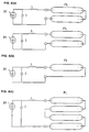
- Figs. 4(a)-(d) schematically show arrangements for the lamp power sources used in the above-described embodiments.
- a circuit is shown having a DC power source 31, a capacitor C, and an inductance L.
- Inductance L is the inductance of a line wire between the lamp power source 31 and a lamp and the inner inductance of capacitor C and is used to set the pulse width and the like.
- reference letters FL are used to designate a xenon flash lamp which is hereinafter called "lamp”.
- two pairs of series-connected lamps FL are each connected to a respective lamp power source 31 and a total of four lamps are caused to emit.
- a single lamp FL can be with each of the multiple power sources and the lamps caused to emit.
- four series-connected lamps FL can be connected to a single power source 31, as is represented in Fig. 4(c).
- the curing effectiveness is increased more dramatically if several lamps are caused to emit in synchronism. Therefore, several lamps are usually synchronized by means of a trigger circuit (not shown in the drawing) for producing emission of all of the lamps at the same time.
- the UV radiation source 20 of the device shown in Fig. 1(a) for bonding discs to one another was caused to emit by the lamp power source shown in Fig. 4(a) and the following was checked:
- an arc length of a lamp of at least 140 mm is necessary.
- the maximum operating voltage maximum voltage with which the lamps do not pass into a continuous operating state
- the voltage of power source 31 in Fig. 4 was, therefore, set to 1800 V with consideration of tolerance.
- the capacitance of capacitor C was changed at the proper time in a range from 123 ⁇ f to 600 ⁇ f, in which the irradiation energy required to cure the UV radiation curable resin can be supplied.
- Fig. 5 shows a plot of the relationship between 1/3 of the pulse width and the input electrical energy for the lamp per irradiated surface at which the aluminum film melts.
- Fig. 6 is a graph of the relationship between the pulse shape of the input current for the lamp and 1/3 of the pulse width.
- the x axis shows 1/3 of the pulse width ⁇ which is shown with a common log scale
- the y axis the input electrical energy J/S (J/cm 2 ) for the lamp per irradiated surface, the input electrical energy for the lamp being designated J (joule) and the irradiated surface S (cm 2 ).
- the irradiated surface was roughly 113 cm 2 (surface area of the disc 6 cm x 6 cm x ⁇ ).
- the values of the y axis in Fig. 5 were computed by dividing the total input electrical energy for the four lamps by 113 cm 2 .
- Fig. 5 shows the input electrical energy E (J/cm 2 ) for the lamp per irradiated surface at which the aluminum film melts.
- E J/cm 2
- the lamp is usually no longer operated when the voltage applied to the lamp reaches a value of 40% of the maximum operating voltage.
- the minimum input electrical energy for the lamp at which the lamp is no longer operated is therefore 31.9 (J), when the value of capacitor C is, for example 123 ⁇ f and the voltage V of the DC source 31 is 1800 V, as was described above. This means that luminous operation of the lamp is not produced unless electrical energy of at least 30 J per pair of power sources is supplied.
- C is the capacitor capacitance
- K is the proportional constant which is determined by the lamp shape and the like
- i(A) is the current
- V o is the charging voltage of the capacitor.
- irradiation can be performed only with a pulse width of at least 88 ⁇ s.
- Fig. 5 shows the above described region using broken lines B and C.
- the flash frequency of the lamp necessary to cure the UV curable resin was checked by changes of the distance d between the UV radiation source 20 and discs 40.
- Fig. 8 shows the result, with the x axis plotting distance d between the lamp center of UV radiation source 20 and the surface of the treatment carrier for discs 40 and the y axis indicating the lamp flashing frequency.
- the flashing frequency is plotted for when the input electrical energy E for the lamp per irradiated surface is 2.84 J/cm 2 and 1/3 of the pulse width is 250 ⁇ s.
- the flash frequency of the lamp necessary to cure the resin hardly changes.
- the flash frequency of the lamp necessary to cure the UV curable resin increases rapidly at distances greater than 50 mm. This indicated that it is desirable that the distance between the lamp center and the surfaces of the discs be at most 50 mm.
- the thickness of treatment carrier 50 With consideration of the tube diameter of lamp 20, the thickness of treatment carrier 50, the thickness of quartz glass sheet 100 and the like with respect to construction, it is difficult to set the distance between the lamp center and the surfaces of the discs at 20 mm or less. Therefore, the lower boundary of the distance d between lamp 20 and discs 40 is roughly 20 mm.
- the light in the wavelength range of greater than roughly 2 to 3 microns is absorbed or reflected by the wavelength selection means, and thus, this light is prevented from reaching the above described articles to be treated.
- the above described wavelength selection means furthermore, transmits the ultraviolet rays, and therefore, does not appreciably hinder cure bonding of the discs.
- wavelength selection means simple handling of the wavelength selection means was achieved by the measure by which polycarbonate substrates, which are used in general, are used as the UV radiation-transmitting substrates of the discs and by which the wavelength selection means is made of plate-like quartz glass, which has the advantages of good thermal resistance, low deterioration by ultraviolet rays and high mechanical strength.
- the input electrical energy for the light radiation means per irradiated surface is set such that the condition according to equation (2), which is represented using the duration ⁇ ( ⁇ s), is satisfied if the current supplied to the light radiation means has 1/3 of its peak value.
Landscapes
- Engineering & Computer Science (AREA)
- Mechanical Engineering (AREA)
- Physics & Mathematics (AREA)
- Electromagnetism (AREA)
- Health & Medical Sciences (AREA)
- Toxicology (AREA)
- Thermal Sciences (AREA)
- Chemical & Material Sciences (AREA)
- Chemical Kinetics & Catalysis (AREA)
- Organic Chemistry (AREA)
- General Health & Medical Sciences (AREA)
- Manufacturing & Machinery (AREA)
- General Chemical & Material Sciences (AREA)
- Manufacturing Optical Record Carriers (AREA)
Abstract
Description
- The invention relates to a process and device for bonding discs on one another, in which there are information recording layers on substrates. The invention relates especially to a process and a bonding device for a digital video disc (or digital versatile disc, such as a compact disk as is used for the storage of computer files and programs or for the digital storage of music) which is formed by bonding two discs to one another, and which hereinafter is called a DVD.
- Recently, development of a DVD with a storage capacity which is roughly six to eight times as great as in a conventional CD (compact disk) has been promoted as the optical disk system for the next generation. The DVD is formed by bonding two thin disks together, at least one disc of which is provided with an information recording surface. The above described two discs are bonded together using resin which is cured with ultraviolet rays. It is usually performed in such a manner that a resin which can be cured using UV rays is uniformly applied using the spin coating method or the like to flat bonding surfaces, and the adhesive is set by irradiating it with ultraviolet rays, from one or both sides, using a high pressure mercury lamp, a metal halide lamp, or the like.
- Figs. 9(a) and 9(b) show arrangements of DVDs. Fig. 9(a) shows the arrangement of a DVD which can be read from both sides with a storage capacity of 9.4 GB; it is called DVD-10. Figure 9(b) shows the arrangement of a DVD with a storage capacity of 4.7 GB, called DVD-5. In Figs. 9(a) and (b), a
substrate 1, through which ultraviolet rays and visible radiation are transmitted, is shown which may be formed, for example, of a thermoplastic resin substrate, such as polycarbonate, acrylic, amorphous polyolefin or the like but, generally, a polycarbonate substrate is often used. - In
substrate 1, according to the recorded information, concave and convex parts are formed on which aninformation recording layer 2 is formed which partially transmits ultraviolet rays and which reflects visible rays. In the DVD of the DVD-10 type, twosubstrates 1 are provided withinformation recording layers 2. In the DVD of the DVD-5 type, only one of the twosubstrates 1 is provided with aninformation recording layer 2.Information recording layer 2 is formed of a film which transmits some of the ultraviolet rays, and which reflects visible rays, for example, an aluminum film, a nickel film, a gold film or the like. But generally, an aluminum film is used. - Furthermore, a
protective film layer 4 is located on theinformation recording layer 2.Protective film layer 4 has ultraviolet radiation transmittance and is formed from a material which has a good adhesive property with respect to the film which formsinformation recording layer 2. Furthermore,protective film layers 4 can be omitted when there is no quality requirement. Also, aresin 5 which can be cured by ultraviolet rays and which is used as an adhesive for bonding thesubstrates 1 to each other, is applied uniformly to the bonding surfaces of the two substrates, and cured by irradiation with ultraviolet rays. - The above described two substrates are bonded together in each type of DVD, i.e., both in DVD-10 and DVD-5, such that
information recording layer 2 lies on the inside. In the following, a substrate which is provided with the above described information recording layer is called a "disc". The thickness of the DVD provided withprotective film layer 4 is roughly 1.2 mm after bonding, as is illustrated in Fig. 9(a). The thickness of the film of information recordinglayers 2 is roughly 48 nm. The diameter of the DVD is usually 120 mm. - These discs are placed on a treatment carrier and irradiated continually with radiant light which is emitted from a UV radiation source and which contains ultraviolet light. Thus, the resin which can be cured by ultraviolet radiation and which has been applied to the discs is cured.
- The aluminum film of the
information recording layer 2 of the disc reflects visible rays and transmits ultraviolet rays; however, the reflection factor is high with respect to the ultraviolet rays, and the UV radiation transmittance is usually 1% or less. Furthermore, the UV radiation transmittance of theprotective film layer 4 is generally about 20 to 50%, although it also depends on its material and its thickness. - Therefore, the ultraviolet rays which irradiate the discs in the bonding process are, for the most part, attenuated until they reach the
resin 5 which can be cured by the UV radiation. To completely cure theresin 5 by uninterrupted irradiation of the disc with ultraviolet rays, therefore, it is necessary to perform the irradiation with ultraviolet rays for a relatively long duration. - If, in this way, uninterrupted irradiation is performed with ultraviolet rays over a long time, the inside of the cage-like body of the irradiation device, the reflector, the treatment carrier and the like are gradually heated up. Therefore, the discs are heated by the secondary IR radiation from the inside of the cage-like body and from the reflector, and by heat conduction from the heated treatment carrier.
- The substrates of the DVDs ordinarily deform when the overall temperature rises above 50° C. Therefore, the effect of the above described heating must be reduced. Therefore, in the above described bonding device in which uninterrupted irradiation with ultraviolet rays is performed, it is necessary to arrange a cooling device or the like. Additionally, it is regarded as disadvantageous that not only deformation of the substrates, but also melting or the like of the aluminum film of the information recording layer occurs.
- Therefore, a first object of the invention is to devise a device for bonding disks to one another in which bonding is obtainable within a short time without deforming the UV radiation-transmitting substrates.
- A second object of the invention is to devise a process for bonding disks on one another in which, using a low capacity power source, a resin which can be cured by UV radiation can be cured with high efficiency without the aluminum film of the information recording layer melting, and a device for executing the process.
- In a device for bonding discs to one another, in which two discs which are comprised of ultraviolet radiation-transmitting substrates, at least one of which has an information recording layer on it which transmits ultraviolet rays and reflects visible rays, are placed one top of one another after applying an adhesive which is formed of a composition which can be cured by UV radiation, and in which the two discs are bonded to one another as a result of irradiation with radiant light containing UV radiation, the side(s) of the information recording layer(s) of the UV radiation-transmitting substrates being used as adhesive surface(s), the above described objects are achieved according to the invention by the fact that light radiation means which irradiate the above described two discs are placed on top of one another with radiant light which contains ultraviolet radiation generate the radiant light at least once in a flash. Additionally, a wavelength selection means is placed in the optical path between the light radiation means and the discs at a distance to the discs which transmits the ultraviolet rays and which absorbs light in a range of wavelengths which are absorbed by the UV radiation-transmitting substrates of the discs, and a cooling device is provided which admits and discharges cooling air between the light radiation means and the wavelength selection means.
- The inventors have found that, in this way, as the ultraviolet radiation source, a light source is used which executes a flash-like emission, for example, a xenon flash lamp, and that by means of one-time or repeated emission(s) of the light source, the discs are irradiated with ultraviolet rays. By using a light source which emits a flash, such as a xenon flash lamp, using a power source with a relative low capacity a resin curable by UV rdiation can be cured with less time as compared to the case for uninterrupted irradiation with ultraviolet rays, heating of the discs due to UV radiation can be further reduced.
- The objects of the invention are, furthermore, advantageously achieved by the wavelength selection means being made of plate-like quartz glass.
- Still further, the objects of the invention are advantageously achieved by the fact that, in the inventive device described above for bonding discs to one another, the light radiation means is located at a distance of from 20 to 50 mm relative to the two discs being bonded to one another, that the above described light radiation means executes irradiation in accordance with the relationships:


- In terms of the process, the object is achieved, using the above described inventive device for bonding discs to one another, by the fact that in flash irradiation of the above described two discs to be bonded to one another with the UV radiation-containing radiant light and when the adhesive sets as a result of passage of the above described radiant light through the above described information recording layer(s) and by irradiation of the above described adhesive with radiant light in the case in which at least the main component of which the information recording layer(s) located on the UV radiation-transmitting substrate(s) is/are made is aluminum, irradiation of the discs with the radiant light is performed in accordance with the relationships:


- Using the above described flash emitting light source under various conditions, the inventors have run tests of the bonding of the discs to one another and checked the conditions under which the resin which can be cured using UV rays can be cured with high efficiency without the aluminum layer melting. As a result, it was found that the amount of electrical energy for the light radiation means (for example, for a xenon flash lamp) in which the aluminum layer of the information recording layer of the disc melts is a function of the duration of the current supplied to the light radiation means.
- Here, it became apparent that under condition

- Furthermore, it was found that the input electrical energy which is necessary for curing the resin increases if the above described 1/3 pulse width τ becomes longer, and that for a 1/3 pulse width τ of greater than 1000 µs, an input electrical energy greater than or equal to 1.5 times the input electrical energy at an optimum 1/3 pulse width is necessary. In addition, it was found that the 1/3 pulse width which can be achieved using circuitry is greater than or equal to 88 µs.
- Additionally, the distance between the lamp and disc, and the flash frequency which is necessary to cure the resin by UV radiation were checked. Here, it was found that the frequency required to cure the resin by UV radiation hardly changes at a distance from the lamp center to the irradiated surfaces of the discs of from 20 mm to 50 mm; however, that it increases quickly at distances greater than 50 mm. Due to the physical configuration of the device, it was difficult to set the distance between the lamp center and the irradiated surfaces of the discs at 20 mm or less.
- These and further objects, features and advantages of the present invention will become apparent from the following description when taken in connection with the accompanying drawings which, for purposes of illustration only, show several embodiments in accordance with the present invention.
-
- Figs. 1(a) and (b) schematically show embodiments of arrangements of the devices according to the invention for bonding discs to one another, Fig. 1 (a) being a schematic of a device for UV irradiation of one side of the discs and Fig. 1(b) showing a schematic of a device for UV irradiation of both sides of the discs;
- Fig. 2 is a graphic depiction of the light transmission characteristic of polycarbonate and of quartz glass;
- Fig. 3 is a graphic depiction of the surface temperature of the discs for irradiation with radiant light according to the invention;
- Figs. 4(a) and 4(b) are schematic representations of a main circuit of the device shown in Fig. 1 for bonding discs to one another, Fig. 4(a) having two lamps that are series-connected in pairs connected to one power source at a time, and Fig. 4(b) showing one lamp at a time being provided with a power source;
- Fig. 4 (c) shows a plurality of lamps being series connected to a power source;
- Fig. 5 is a graphic depiction of the relation between the melting energy of aluminum and 1/3 of the pulse width;
- Fig. 6 schematically depicts 1/3 of the pulse width;
- Fig. 7 is a graphic depiction of the relation between the total energy required for curing and 1/3 of the pulse width;
- Fig. 8 is a graphic depiction of the relation between the distance between the lamp center and the surface of the disc carrier and the flash frequency necessary for curing; and
- Figs. 9(a) and 9(b) schematically show DVD arrangements, Fig. 9(a) showing the arrangement of a DVD which can be read on both sides having a storage capacity of 9.4 GB, and in Fig. 9(b) showing the arrangement of a DVD with a storage capacity of 4.7 GB.
- Figs. 1(a) and (b) schematically show embodiments of the devices according to the invention for bonding discs to one another, Fig. 1(a) showing an example of UV irradiation of one side of the discs, and Fig. 1(b) showing an example of ultraviolet irradiation of both sides of the discs.
- In the drawings, a cage-
like body 10 contains at least one UV radiation source 20 (two in Fig. 1(b)) which emits radiant UV light in flashes, and which, for example, comprises a xenon flash lamp. Areflector 30 is provided to reflect the radiant light from eachUV radiation source 20. Furthermore, aquartz glass sheet 100 is located between eachUV radiation source 20 and thediscs 40 at a distance todiscs 40. - Each
quartz glass sheet 100 is cooled by a flow of cooling air which is supplied by afan 70 through achannel 80 to thequartz glass 100. The cooling air (represented by arrows) passes across thequartz glass sheet 100 in heat exchange relationship thereto and then is discharged frombody 10 to the outside by means of achannel 81. - Furthermore, in Fig. 1(a), a
treatment carrier 50 is provided for supporting thediscs 40 to be bonded together, and in Fig. 1(b) aholding component 60, which is made of a UV radiation-transmitting material, is provided to hold thediscs 40, instead. - Fig. 2 is a graph of the light transmission characteristics of polycarbonate of which the two substrates of
discs 40 are made, and of the quartz glass, the x-axis showing the wavelengths (microns) and the y-axis showing the transmission factor (%). - As was described above,
UV radiation source 20 comprises a xenon flash lamp which emits radiant light which contains UV rays and this light a peak value of light intensity in the course of repeated flashing in a range of wavelengths and which includes wavelengths longer than 2 to 3 microns. - As is apparent from Fig. 2, in the polycarbonate which forms the substrates, the transmission factor decreases starting from 2 to 3 micron wavelengths. Here, especially light in a range of wavelengths longer than roughly 5 microns is hardly transmitted at all. This means that light in a range of wavelengths longer than roughly 2 to 3 microns is absorbed, and heat is stored in the interior of the disc material.
- On the other hand, also in the quartz glass, the transmittance begins to decrease starting from 2 to 3 micron wavelengths. Here, especially light is hardly transmitted at all in a range of wavelengths longer than roughly 4 microns. This means that, here also, light in a wavelength range with wavelengths longer than roughly 2 to 3 microns is absorbed.
- Therefore, if
quartz glass sheet 100 is located between theUV radiation source 20 and thediscs 40 at a distance from thediscs 40,quartz glass 100 absorbs the light in the wavelength range of greater than roughly 2 to 3 microns which is contained in the radiant light from theUV radiation source 20. As a result, the light in the above described range which reaches the polycarbonate substrate ofdiscs 40 is reduced. Furthermore, there is no heat conduction fromquartz glass 100 todiscs 40, becausequartz glass sheet 100, with a temperature which rises due to absorption of light in the above described wavelength range, anddiscs 40 are spaced apart from one another. Thus, it becomes possible to maintain the amount of heat which is stored indiscs 40 at a low level. Still further,quartz glass sheet 100 hardly hinders cure bonding ofdiscs 40, sincequartz glass sheet 100 transmits up to at least 90% of the UV radiation. - On the other hand, for treatment of
several discs 40, the waiting time between cycles is shortened if, to increase the throughput, the transport time fordiscs 40 is shortened. In this way, by shortening the emission pause between flashes of the xenon flash lamp serving asUV radiation source 20, as a result, the average irradiation energy increases and the temperature ofquartz glass sheet 100 increases even more. Here, the possibility cannot be precluded that under certain circumstances the effect of secondary IR radiation fromquartz glass sheet 100 will not become negligible. - In this embodiment, however, the
quartz glass sheet 100 which is heated by absorption of light in the wavelength range of greater than roughly 2 to 3 microns is cooled. In the above described case that the throughput is to be increased, it becomes possible to reduce the effect of secondary IR radiation fromquartz glass sheet 100 ontodiscs 40. - To confirm the action of the device for bonding discs to one another in this embodiment, in the device for bonding discs to one another with the arrangement shown in Fig. 1(a), the amount of cooling air for
quartz glass sheet 100 was changed and the surface temperature of thediscs 40 was measured. Furthermore, a measurement was taken in the case in which thequartz glass sheet 100 was not present. The following measurement conditions were also provided: - UV radiation source: four xenon flash lamps
- Emission energy in one emission: 400 J at a time
- Emission frequency: 30 times per disc
- Emission period: 1 time per second
- Number of discs to be treated: 18
- Temperature measurement position: center region of the disc surface
- Temperature measurement means: contact thermometer (during the 30 seconds after emission, measurement and exchange of discs are performed)
- Amount of cooling air: 0; 2.2; 4.4 m3/min
- Fig. 3 shows the results of the above described measurements. In the figure, the x-axis represents the number of discs treated with UV radiation and the y-axis the surface temperature of the discs.
- As is apparent from Fig. 3, the surface temperature of
discs 40 rises above 50° C after UV radiation treatment if the number of treateddiscs 40 exceeds three, in the case in which there is noquartz glass sheet 100 between theUV radiation source 20 anddiscs 40. The surface temperature ofdiscs 40 rose to roughly 70° C, whenmore discs 40 were treated. As a result, deformation ofdiscs 40 occurred. - On the other hand, in the case in which
quartz glass sheet 100 was located between theUV radiation source 20 anddiscs 40 and in which the amount of coolant air was 0 m3/min, the surface temperature of the discs was 45° C when treateddiscs 40 reached the number 18. On the other hand, the surface temperature ofdiscs 40 in the case of amounts of cooling air of 2.2 m3/min and 4.4 m3/min was 35° C and 31° C, respectively, when treateddiscs 40 reached the number 18. In no case did deformation ofdiscs 40 occur. But, it was found that, especially in the case of cooling ofquartz glass sheet 100 with the cooling air, the surface temperature ofdiscs 40 is maintained at less than or equal to 40° C, even when the number ofdiscs 40 treated reached 18. - This means that the measure by which the flash-emitting xenon flash lamp is used as
UV radiation source 20 and by which there isquartz glass sheet 100 betweenUV radiation source 20 anddiscs 40 at a distance fromdiscs 40 prevents the portion of the radiant light which is emitted from thisUV radiation source 20 which is in the wavelength range greater than roughly 2 to 3 microns from reachingdiscs 40, even if theUV radiation source 20 becomes heated. Furthermore, there is no heat conduction fromquartz glass sheet 100 todiscs 40, since thequartz glass sheet 100 it is spaced apart from thediscs 40. In this way, the disadvantage of deformation ofdiscs 40 by heating is eliminated, and it becomes possible to cementdiscs 40 to one another in a short time. - Therefore, a large disc cooling device for supplying a large amount of cooling air to the discs is no longer needed. Furthermore, there is no longer the danger that the quality of
discs 40 will be adversely affected as a result of fine impurities from the cooling air adhering on the surfaces ofdiscs 40. Still further, cure bonding ofdiscs 40 is hardly hindered by the presence of thequartz glass sheet 100 since transmits up to at least 90% of the ultraviolet radiation. - In addition, a situation was assumed in which the waiting time between cycles was shortened to increase the throughput. Here, after completion of the measurement of the surface temperature of the
eighteenth disc 40, without replacingdiscs 40, the xenon flash lamp was used to intermittently emit UV light for an emission period of 3 times per second for a duration of ten minutes, after which the surface temperature of thedisc 40 was measured again. - The surface temperature of the
disc 40, in spite of these severe conditions, was 45° C in the case of a cooling air flow of 2.2 m3/min, and was 41° C in the case of a cooling air flow of 4.4 m3/min. In any case, the surface temperature ofdisc 40 was kept at less than or equal to 50° C, and deformation ofdisc 40 was not observed. - This means that, in this embodiment of the device for bonding discs together, by the cooling
quartz glass sheet 100 which is heated by absorption of light in the wavelength range of greater than roughly 2 to 3 microns, the effect of secondary IR radiation fromquartz glass sheet 100 ondiscs 40 was essentially eliminated, even in the case in which the waiting time between cycles was shortened due to the shortening of transportation time for thediscs 40 to obtain an increase in throughput. - In the above described embodiment, a case was described in which the UV radiation-transmitting substrate was a polycarbonate substrate. However, the invention can also be applied to the case of an acrylic substrate or one formed of an amorphous polyolefin substrate because such substrates have the same transmittance characteristic as the polycarbonate substrate.
- In the above described embodiment, plate-like quartz glass was used as the wavelength selection means which transmits ultraviolet rays and which does not allow light in the wavelength range of greater than roughly 2 to 3 microns to be emitted onto the discs. However, the invention is not limited thereto, and for example, plate-like borosilicate glass or the like can be used.
- However, the quartz glass especially advantageous since it has good heat resistance, is not subject to significant deterioration due to exposure the ultraviolet rays and has high mechanical strength. Handling thereof as the wavelength selection means which does not allow light in the wavelength range of greater than 2 to 3 microns to be emitted onto the discs is therefore simple.
- Furthermore, in the above described embodiment, the measure by which the wavelength selection means absorbs light in the wavelength range of greater than roughly 2 to 3 microns reduces the amount of irradiation of the discs with light in this wavelength range. But, for example, the surface of the glass which transmits the ultraviolet rays and which absorbs the IR rays in the above described wavelength range can be provided with a multilayer dielectric film and can partially reflect the light in the above described wavelength range.
- Figs. 4(a)-(d) schematically show arrangements for the lamp power sources used in the above-described embodiments. In Figs. 4(a)-(c), a circuit is shown having a
DC power source 31, a capacitor C, and an inductance L. Inductance L is the inductance of a line wire between thelamp power source 31 and a lamp and the inner inductance of capacitor C and is used to set the pulse width and the like. Furthermore, reference letters FL are used to designate a xenon flash lamp which is hereinafter called "lamp". In Fig. 4(a), two pairs of series-connected lamps FL are each connected to a respectivelamp power source 31 and a total of four lamps are caused to emit. Furthermore, as is shown in Fig. 4(b), instead of pairs of lamps, a single lamp FL can be with each of the multiple power sources and the lamps caused to emit. Still further, four series-connected lamps FL can be connected to asingle power source 31, as is represented in Fig. 4(c). - Additionally, in the case of using several lamps as
UV radiation source 20, the curing effectiveness is increased more dramatically if several lamps are caused to emit in synchronism. Therefore, several lamps are usually synchronized by means of a trigger circuit (not shown in the drawing) for producing emission of all of the lamps at the same time. - The
UV radiation source 20 of the device shown in Fig. 1(a) for bonding discs to one another was caused to emit by the lamp power source shown in Fig. 4(a) and the following was checked: - It was checked the relation between 1/3 of the pulse width and the input electrical energy for the lamp at which the aluminum film which comprises the information recording layer of
disc 40 melts. In this test, two pairs of UV radiation sources 20 (four lamps for one pair of UV radiation sources) were located on one side of the discs. The four lamps were flashed at the same time, and irradiation was performed from one side of the discs, the distance between the lamp center andtreatment carrier 50 having been set to 45 mm and the distance between the surfaces on whichdiscs 40 are placed and the quartz glass having been set to 25 mm. - The above described 1/3 pulse width was changed by changes of the value of inductance L of the
lamp power sources 31 and of the value of capacitor C. Furthermore, the input electrical energy for the lamp was changed by changes of the value of capacitor C and of the value of the charging voltage. - To irradiate a disc with a diameter of 120 mm with a uniform illumination intensity, an arc length of a lamp of at least 140 mm is necessary. To series connect and operate two lamps with an arc length of at least 140 mm, the maximum operating voltage (maximum voltage with which the lamps do not pass into a continuous operating state) is 2000 V per lamp pair. The voltage of
power source 31 in Fig. 4 was, therefore, set to 1800 V with consideration of tolerance. Furthermore, the capacitance of capacitor C was changed at the proper time in a range from 123 µf to 600 µf, in which the irradiation energy required to cure the UV radiation curable resin can be supplied. - Fig. 5 shows a plot of the relationship between 1/3 of the pulse width and the input electrical energy for the lamp per irradiated surface at which the aluminum film melts. An input electrical energy Em for the lamp per irradiated surface S at which the surface temperature of the aluminum film of the disc reaches its melting point, i.e., 660° C, by flash irradiation was plotted. Fig. 6 is a graph of the relationship between the pulse shape of the input current for the lamp and 1/3 of the pulse width.
- In Fig. 5, the x axis shows 1/3 of the pulse width τ which is shown with a common log scale, and the y axis the input electrical energy J/S (J/cm2) for the lamp per irradiated surface, the input electrical energy for the lamp being designated J (joule) and the irradiated surface S (cm2).
- In this example, the irradiated surface was roughly 113 cm2 (surface area of the disc 6 cm x 6 cm x π). The values of the y axis in Fig. 5 were computed by dividing the total input electrical energy for the four lamps by 113 cm2.
- By means of line A, Fig. 5 shows the input electrical energy E (J/cm2) for the lamp per irradiated surface at which the aluminum film melts. The aluminum film melts when energy is supplied in an amount which exceeds line A.
- In addition, in Fig. 5, together with the line A, using broken line B, the upper boundary of 1/3 of the pulse width described below was found, and using broken line C, the lower boundary thereof was shown. The region surrounded by line A and broken lines B and C represents a usable range.
- The above described test showed that input electrical energy Em (J/cm2) for the lamp per irradiated surface at which the aluminum film melts, and 1/3 of pulse width τ (microseconds) are represented by the following formula (1) in which log is the common logarithm:

- The input electrical energy E (J/cm2) for the lamp per irradiated surface must therefore satisfy the condition according to the following equation:

- The above described equations must, furthermore, also be satisfied for each side in the case of simultaneous irradiation of both sides of the discs.
- The lamp is usually no longer operated when the voltage applied to the lamp reaches a value of 40% of the maximum operating voltage.
- The value of the input electrical energy for the lamp which corresponds to the irradiation energy of the lamp is computed by following formula (3) in which C is the capacitance of the capacitor in Fig. 4 and V is the lamp voltage:

- The minimum input electrical energy for the lamp at which the lamp is no longer operated is therefore 31.9 (J), when the value of capacitor C is, for example 123 µf and the voltage V of the
DC source 31 is 1800 V, as was described above. This means that luminous operation of the lamp is not produced unless electrical energy of at least 30 J per pair of power sources is supplied. - Here, 1/3 of the pulse width and the total energy (total energy being equal to irradiation frequency x input electrical energy for the lamp/ irradiated surface) which is necessary for curing the resin were checked.
- The above described 1/3 pulse width was changed in the same manner as in (1), by changes of the values of inductance L of the lamp power source shown in Fig. 4 and of capacitor C. Furthermore, the input electrical energy for the lamp was changed by changes of the value of capacitor C shown in Fig. 4, the charging voltage and the irradiation frequency.
- In this case, the result shown in Fig. 7 was obtained. As is shown in the figure, the total energy required to cure the UV curable resin increases the more, the longer the pulse width becomes. It was found that, at 1/3 of the pulse width τ of 1000 µs, energy which is 1.5 times as much as at 500 µs is required.
- At a 1/3 of the pulse width of 1000 µs, it is therefore necessary that the repetition frequency of irradiation be increased to supply more energy to the discs. At the same input electrical energy per flash, the throughput drops. Furthermore, if the frequency of repetition of irradiation is accelerated to prevent a drop of throughput, the power necessary for treatment per disk increases. This means that the efficiency of treatment decreases if 1/3 of pulse width τ is not set to less than or equal to 1000 µs.
- Next, a pulse width which can be accomplished using circuitry is determined. The minimum pulse width in the case in which there is no floating inductance can be derived from the differential equation shown below in (4) for a known xenon flash lamp.

- In the above described equation, C is the capacitor capacitance, K is the proportional constant which is determined by the lamp shape and the like, i(A) is the current, and Vo is the charging voltage of the capacitor. Based on the above described equation (4), the
minimum 1/3 of the pulse width τ of the discharge current is computed by the following formula:
- If, in this example, for the above described voltage V, a voltage of 1800 V of one pair of power sources to which the two lamps, are series connected is used, a minimum value of the capacitor of 123 µf per lamp pair is used for C and a lamp value of 42 is used for K, the result is the following:

- This means that irradiation can be performed only with a pulse width of at least 88 µs.
- As was described above, the following must be satisfied with respect to 1/3 of the pulse width τ:

- Fig. 5, as was described above, shows the above described region using broken lines B and C.
- In the device shown in Fig. 1(a), the flash frequency of the lamp necessary to cure the UV curable resin was checked by changes of the distance d between the
UV radiation source 20 anddiscs 40. - Fig. 8 shows the result, with the x axis plotting distance d between the lamp center of
UV radiation source 20 and the surface of the treatment carrier fordiscs 40 and the y axis indicating the lamp flashing frequency. In the figure, the flashing frequency is plotted for when the input electrical energy E for the lamp per irradiated surface is 2.84 J/cm2 and 1/3 of the pulse width is 250 µs. - As is apparent from the drawing, at a distance between the lamp center and the surface of the discs of from 20 to 50 mm, the flash frequency of the lamp necessary to cure the resin hardly changes. The flash frequency of the lamp necessary to cure the UV curable resin, however, increases rapidly at distances greater than 50 mm. This indicated that it is desirable that the distance between the lamp center and the surfaces of the discs be at most 50 mm.
- With consideration of the tube diameter of
lamp 20, the thickness oftreatment carrier 50, the thickness ofquartz glass sheet 100 and the like with respect to construction, it is difficult to set the distance between the lamp center and the surfaces of the discs at 20 mm or less. Therefore, the lower boundary of the distance d betweenlamp 20 anddiscs 40 is roughly 20 mm. - In (1) through (3) above, a device was examined which irradiates the discs from only one side, as in Fig. 1(a). But, it can be expected that the irradiation conditions are also the same in the case of irradiation of the discs from the two sides, as in Fig. 1(b), in which the two sides are provided with information recording layers such as DVD-10 or the like.
- In the device according to the invention for bonding discs to one another, of the radiant light which is emitted when the light emission means has reached a heated state, the light in the wavelength range of greater than roughly 2 to 3 microns is absorbed or reflected by the wavelength selection means, and thus, this light is prevented from reaching the above described articles to be treated. This eliminates the disadvantage that the articles to be treated, that is, the two discs which are placed on top of one another, are deformed by heating and the discs are able to be bonded to one another within a short time by cure bonding by means of the adhesive of a composition which can be cured with UV radiation. The above described wavelength selection means, furthermore, transmits the ultraviolet rays, and therefore, does not appreciably hinder cure bonding of the discs.
- Therefore, a large cooling device for supplying a large amount of cooling air to the discs is no longer needed. Furthermore, there is no longer the danger that the quality of the discs will be adversely affected as a result of adhesion of fine impurities from the cooling air on the surfaces of the discs.
- Furthermore, in the case in which the waiting time between cycles is shortened to increase the throughput by shortening the transport time for the discs, the effect of secondary IR radiation from the quartz glass onto the discs was essentially eliminated. The same is true also, when the pause of emission of the light radiation means is shortened and as a result the average irradiation energy which is supplied to the wavelength selection means is increased.
- In addition, simple handling of the wavelength selection means was achieved by the measure by which polycarbonate substrates, which are used in general, are used as the UV radiation-transmitting substrates of the discs and by which the wavelength selection means is made of plate-like quartz glass, which has the advantages of good thermal resistance, low deterioration by ultraviolet rays and high mechanical strength.
- Furthermore, according to the invention, the input electrical energy for the light radiation means per irradiated surface is set such that the condition according to equation (2), which is represented using the duration τ (µs), is satisfied if the current supplied to the light radiation means has 1/3 of its peak value. In this way, two discs can be bonded to one another with relatively low input electrical energy and with high efficiency without the aluminum of the information recording film melting, or without thermal deformation of the discs occurring.
- It is to be understood that although preferred embodiments of the invention have been described, various other embodiments and variations may occur to those skilled in the art. Any such other embodiments and variations which fall within the scope and spirit of the present invention are intended to be covered by the following claims.
Claims (5)
- Device for bonding together two disc substrates, each of which has a UV transmissive base, at least one disc substrate of which has, on the UV transmissive base thereof, an information recording layer which transmits ultraviolet rays and reflects visible rays, with the disc substrates on top of one another with a bonding agent therebetween that is made of a UV curable composition, the information recording layer of said at least one of the disc substrates facing the other of the disc substrates, comprising
comprisinga light irradiation means (20) for irradiating to the two disc substrates with light which contains ultraviolet rays with one or more flashes;a wavelength selection means for transmitting ultraviolet rays and absorbing light in a range of wavelengths which are absorbed by the disc substrates, said wavelength selection means being disposed in an optical path between the light irradiation means from the disc separating the light irradiation means (20) from the disc substrates;and a cooling means (70,80,81) which supplies and discharges cooling air between the light irradiation means (20) and the wavelength selection means. - Device for bonding discs according to claim 1, characterized in that the wavelength selection means comprises a quartz glass plate (100).
- Device for bonding discs according to claim 1, characterized in that the light radiation means (20) is located at a distance from 20 to 50 mm from the two discs (40); wherein the light radiation means (20) emits radiant light in accordance with the relationships:

- Device for bonding discs according to claim 1, characterized in that the light radiation means comprises a xenon flash lamp.
- Process for bonding two disc substrates, each of which has a UV transmissive base, on top of one another with a bonding agent therebetween that is made of a composition which can be cured with UV radiation, at least one of facing sides of disc substrates having an information recording layer thereon which transmits ultraviolet rays and reflects visible rays and which has said bonding agent on a surface thereof, comprising the steps of:emitting radiant light which contains ultraviolet radiation toward the disc substrates at least once in a flash using a light radiation means (20);absorbing light in a range of wavelengths which are absorbed by the disc substrates from the radiant light emitted using wavelength selection means disposed in an optical path between the light irradiation means (20) and the disc substrates at a distance from the disc substrates, and transmitting ultraviolet rays of said radiant light on to said disc substrates;directing cooling air between the light radiation means (20) and the wavelength selection;setting the bonding agent as a result of passage of the ultraviolet rays of the radiant light through the information recording layer and by irradiation of the bonding agent with the ultraviolet rays of the radiant light;
wherein irradiation of the disc substrates with radiant light is performed in accordance with the relationships:
Applications Claiming Priority (6)
| Application Number | Priority Date | Filing Date | Title |
|---|---|---|---|
| JP15925796A JP3176844B2 (en) | 1996-05-31 | 1996-05-31 | Disk bonding device |
| JP159257/96 | 1996-05-31 | ||
| JP15925796 | 1996-05-31 | ||
| JP16905596A JP3298791B2 (en) | 1996-06-28 | 1996-06-28 | Disc bonding method and apparatus |
| JP169055/96 | 1996-06-28 | ||
| JP16905596 | 1996-06-28 |
Publications (2)
| Publication Number | Publication Date |
|---|---|
| EP0810592A1 true EP0810592A1 (en) | 1997-12-03 |
| EP0810592B1 EP0810592B1 (en) | 2003-01-02 |
Family
ID=26486106
Family Applications (1)
| Application Number | Title | Priority Date | Filing Date |
|---|---|---|---|
| EP97109113A Expired - Lifetime EP0810592B1 (en) | 1996-05-31 | 1997-05-30 | Process and device for bonding discs to one another |
Country Status (4)
| Country | Link |
|---|---|
| US (1) | US5785793A (en) |
| EP (1) | EP0810592B1 (en) |
| CA (1) | CA2206613C (en) |
| DE (1) | DE69718100T2 (en) |
Cited By (1)
| Publication number | Priority date | Publication date | Assignee | Title |
|---|---|---|---|---|
| EP1387765A1 (en) * | 2001-05-04 | 2004-02-11 | Xenon Corporation | A dual lamp system for manufacturing dvd |
Families Citing this family (17)
| Publication number | Priority date | Publication date | Assignee | Title |
|---|---|---|---|---|
| US5779855A (en) * | 1995-08-30 | 1998-07-14 | Kitano Engineering Co., Ltd. | Apparatus for curing an optical disc |
| JP2001505349A (en) * | 1997-05-27 | 2001-04-17 | コーニンクレッカ フィリップス エレクトロニクス エヌ ヴィ | Device for curing the adhesive between two layers of information carrier |
| US5880694A (en) * | 1997-06-18 | 1999-03-09 | Hughes Electronics Corporation | Planar low profile, wideband, wide-scan phased array antenna using a stacked-disc radiator |
| TW412743B (en) * | 1997-10-22 | 2000-11-21 | Kuraray Co | Method for manufacture eximer laser disk |
| US6254809B1 (en) | 1998-05-19 | 2001-07-03 | Steag Hamatech, Inc. | System and method for curing a resin disposed between a top and bottom substrate with thermal management |
| JP3581246B2 (en) * | 1997-12-17 | 2004-10-27 | パイオニア株式会社 | Manufacturing method of bonded optical disk |
| US6224709B1 (en) | 1998-01-27 | 2001-05-01 | Ricoh Company, Ltd. | Method for assembling parts |
| JP3280313B2 (en) | 1998-06-01 | 2002-05-13 | 北野エンジニアリング株式会社 | Optical disc manufacturing method |
| JP2000076710A (en) * | 1998-08-26 | 2000-03-14 | Matsushita Electric Ind Co Ltd | Method and device for sticking substrate for optical disk |
| JP2002528846A (en) * | 1998-11-04 | 2002-09-03 | ゼノン・コーポレーション | Spiral lamp for UV curing of coatings and joining digital versatile discs (DVD) or compact discs (CD) |
| DE60019679T2 (en) | 1999-06-11 | 2006-01-19 | Kitano Engineering Co., Ltd., Komatsushima | Apparatus for curing an optical disk |
| US6395124B1 (en) | 1999-07-30 | 2002-05-28 | 3M Innovative Properties Company | Method of producing a laminated structure |
| JP2001093197A (en) * | 1999-09-27 | 2001-04-06 | Matsushita Electric Ind Co Ltd | Device for manufacturing optical recording medium |
| US20020053397A1 (en) * | 2000-11-06 | 2002-05-09 | Dainippon Ink And Chemicals, Inc. | Method for bonding members, and disc manufacturing method and device |
| US6955739B2 (en) * | 2001-06-19 | 2005-10-18 | 3M Innovative Properties Company | Method for adhering substrates using ultraviolet activatable adhesive film and an ultraviolet irradiation apparatus |
| US20040134603A1 (en) * | 2002-07-18 | 2004-07-15 | Hideo Kobayashi | Method and apparatus for curing adhesive between substrates, and disc substrate bonding apparatus |
| DE102011005901A1 (en) * | 2011-03-22 | 2012-09-27 | Lisa Dräxlmaier GmbH | Cold lamination with radiation |
Citations (3)
| Publication number | Priority date | Publication date | Assignee | Title |
|---|---|---|---|---|
| DE3734443A1 (en) * | 1987-10-12 | 1989-04-20 | Albert Kreitmair | Apparatus for the photopolymerisation of photocuring otoplastics |
| EP0706178A2 (en) * | 1994-10-03 | 1996-04-10 | Matsushita Electric Industrial Co., Ltd. | Optical information medium, method for producing the optical information medium, and unit for producing the optical information medium |
| EP0762409A1 (en) * | 1995-08-15 | 1997-03-12 | Dainippon Ink And Chemicals, Inc. | Disc bonding method and device therefor |
Family Cites Families (3)
| Publication number | Priority date | Publication date | Assignee | Title |
|---|---|---|---|---|
| US4877475A (en) * | 1984-11-01 | 1989-10-31 | Matsushita Electric Industrial Co., Ltd. | Method for producing information storage disk |
| US5416127A (en) * | 1993-01-28 | 1995-05-16 | National Starch And Chemical Investment Holding Corporation | Radiation curable hot melt pressure sensitive adhesives |
| US5684778A (en) * | 1994-09-27 | 1997-11-04 | Matsushita Electric Industrial Co., Ltd. | Initialization process for a phase change recording medium with a zero level drop in flash light emission |
-
1997
- 1997-05-30 CA CA002206613A patent/CA2206613C/en not_active Expired - Fee Related
- 1997-05-30 DE DE69718100T patent/DE69718100T2/en not_active Expired - Lifetime
- 1997-05-30 US US08/866,072 patent/US5785793A/en not_active Expired - Lifetime
- 1997-05-30 EP EP97109113A patent/EP0810592B1/en not_active Expired - Lifetime
Patent Citations (3)
| Publication number | Priority date | Publication date | Assignee | Title |
|---|---|---|---|---|
| DE3734443A1 (en) * | 1987-10-12 | 1989-04-20 | Albert Kreitmair | Apparatus for the photopolymerisation of photocuring otoplastics |
| EP0706178A2 (en) * | 1994-10-03 | 1996-04-10 | Matsushita Electric Industrial Co., Ltd. | Optical information medium, method for producing the optical information medium, and unit for producing the optical information medium |
| EP0762409A1 (en) * | 1995-08-15 | 1997-03-12 | Dainippon Ink And Chemicals, Inc. | Disc bonding method and device therefor |
Cited By (2)
| Publication number | Priority date | Publication date | Assignee | Title |
|---|---|---|---|---|
| EP1387765A1 (en) * | 2001-05-04 | 2004-02-11 | Xenon Corporation | A dual lamp system for manufacturing dvd |
| EP1387765A4 (en) * | 2001-05-04 | 2005-12-28 | Xenon Corp | A dual lamp system for manufacturing dvd |
Also Published As
| Publication number | Publication date |
|---|---|
| DE69718100T2 (en) | 2003-07-10 |
| EP0810592B1 (en) | 2003-01-02 |
| US5785793A (en) | 1998-07-28 |
| CA2206613C (en) | 2000-12-19 |
| CA2206613A1 (en) | 1997-11-30 |
| DE69718100D1 (en) | 2003-02-06 |
Similar Documents
| Publication | Publication Date | Title |
|---|---|---|
| US5785793A (en) | Process and device for bonding discs to one another | |
| EP0762409B1 (en) | Disc bonding method and device therefor | |
| KR100218211B1 (en) | Manufacturing method and device of optical information recording media | |
| US7896053B2 (en) | Non-destructive component separation using infrared radiant energy | |
| US4204119A (en) | Method of reading thermoluminescent dosimeter | |
| JPH06349813A (en) | Apparatus for heating of substrate | |
| EP1005037A1 (en) | Optical disk and method of manufacturing optical disk | |
| JP3270688B2 (en) | Disk bonding device | |
| JP3176844B2 (en) | Disk bonding device | |
| JP3298791B2 (en) | Disc bonding method and apparatus | |
| JPH06101149B2 (en) | Crystallization method of optical information recording medium | |
| JP3354825B2 (en) | UV irradiation device | |
| JP4339410B2 (en) | Equipment for photo-initiated chemical crosslinking of materials | |
| JPH08153343A (en) | Production of optical information recording medium and production apparatus | |
| JP2017006890A (en) | Light radiation device and light radiation method | |
| JP2007191543A (en) | Ultraviolet-curing method and ultraviolet-curing apparatus | |
| KR100379401B1 (en) | apparatus for generating ultraviolet rays | |
| JPH10199053A (en) | Method for sticking disks to each other, and device therefor | |
| JP2816320B2 (en) | Crystallization method for optical information recording medium | |
| JPH0770093B2 (en) | Crystallization method of optical information recording medium | |
| JPH11189748A (en) | Pasting together, device therefor, and production of light disk | |
| JPH11339331A (en) | Method and device to manufacture disk | |
| CN114423101A (en) | Infrared heating device with light shield plate | |
| JP2006291152A (en) | Device for curing adhesive agent | |
| Panico | Pulsed UV Curing for DVD Production |
Legal Events
| Date | Code | Title | Description |
|---|---|---|---|
| PUAI | Public reference made under article 153(3) epc to a published international application that has entered the european phase |
Free format text: ORIGINAL CODE: 0009012 |
|
| AK | Designated contracting states |
Kind code of ref document: A1 Designated state(s): CH DE FR IE LI NL |
|
| 17P | Request for examination filed |
Effective date: 19980209 |
|
| GRAG | Despatch of communication of intention to grant |
Free format text: ORIGINAL CODE: EPIDOS AGRA |
|
| 17Q | First examination report despatched |
Effective date: 20020605 |
|
| GRAG | Despatch of communication of intention to grant |
Free format text: ORIGINAL CODE: EPIDOS AGRA |
|
| GRAH | Despatch of communication of intention to grant a patent |
Free format text: ORIGINAL CODE: EPIDOS IGRA |
|
| RIN1 | Information on inventor provided before grant (corrected) |
Inventor name: YOKOTA, TOSHIO Inventor name: EBISAWA, SHOUEI Inventor name: ARAI, TETSUJI |
|
| GRAH | Despatch of communication of intention to grant a patent |
Free format text: ORIGINAL CODE: EPIDOS IGRA |
|
| GRAA | (expected) grant |
Free format text: ORIGINAL CODE: 0009210 |
|
| AK | Designated contracting states |
Kind code of ref document: B1 Designated state(s): CH DE FR IE LI NL |
|
| REG | Reference to a national code |
Ref country code: CH Ref legal event code: EP |
|
| REG | Reference to a national code |
Ref country code: IE Ref legal event code: FG4D |
|
| REF | Corresponds to: |
Ref document number: 69718100 Country of ref document: DE Date of ref document: 20030206 Kind code of ref document: P |
|
| REG | Reference to a national code |
Ref country code: CH Ref legal event code: NV Representative=s name: ROTTMANN, ZIMMERMANN + PARTNER AG |
|
| ET | Fr: translation filed | ||
| PLBE | No opposition filed within time limit |
Free format text: ORIGINAL CODE: 0009261 |
|
| STAA | Information on the status of an ep patent application or granted ep patent |
Free format text: STATUS: NO OPPOSITION FILED WITHIN TIME LIMIT |
|
| 26N | No opposition filed |
Effective date: 20031003 |
|
| PGFP | Annual fee paid to national office [announced via postgrant information from national office to epo] |
Ref country code: FR Payment date: 20060517 Year of fee payment: 10 |
|
| PGFP | Annual fee paid to national office [announced via postgrant information from national office to epo] |
Ref country code: IE Payment date: 20060526 Year of fee payment: 10 |
|
| PGFP | Annual fee paid to national office [announced via postgrant information from national office to epo] |
Ref country code: CH Payment date: 20060530 Year of fee payment: 10 |
|
| REG | Reference to a national code |
Ref country code: CH Ref legal event code: PL |
|
| NLS | Nl: assignments of ep-patents |
Owner name: USHIO DENKI KABUSHIKI KAISYA Effective date: 20071126 |
|
| REG | Reference to a national code |
Ref country code: IE Ref legal event code: MM4A |
|
| PG25 | Lapsed in a contracting state [announced via postgrant information from national office to epo] |
Ref country code: LI Free format text: LAPSE BECAUSE OF NON-PAYMENT OF DUE FEES Effective date: 20070531 Ref country code: CH Free format text: LAPSE BECAUSE OF NON-PAYMENT OF DUE FEES Effective date: 20070531 |
|
| REG | Reference to a national code |
Ref country code: FR Ref legal event code: ST Effective date: 20080131 |
|
| PG25 | Lapsed in a contracting state [announced via postgrant information from national office to epo] |
Ref country code: IE Free format text: LAPSE BECAUSE OF NON-PAYMENT OF DUE FEES Effective date: 20070530 |
|
| PG25 | Lapsed in a contracting state [announced via postgrant information from national office to epo] |
Ref country code: FR Free format text: LAPSE BECAUSE OF NON-PAYMENT OF DUE FEES Effective date: 20070531 |
|
| PGFP | Annual fee paid to national office [announced via postgrant information from national office to epo] |
Ref country code: DE Payment date: 20150527 Year of fee payment: 19 |
|
| PGFP | Annual fee paid to national office [announced via postgrant information from national office to epo] |
Ref country code: NL Payment date: 20150409 Year of fee payment: 19 |
|
| REG | Reference to a national code |
Ref country code: DE Ref legal event code: R119 Ref document number: 69718100 Country of ref document: DE |
|
| REG | Reference to a national code |
Ref country code: NL Ref legal event code: MM Effective date: 20160601 |
|
| PG25 | Lapsed in a contracting state [announced via postgrant information from national office to epo] |
Ref country code: NL Free format text: LAPSE BECAUSE OF NON-PAYMENT OF DUE FEES Effective date: 20160601 |
|
| PG25 | Lapsed in a contracting state [announced via postgrant information from national office to epo] |
Ref country code: DE Free format text: LAPSE BECAUSE OF NON-PAYMENT OF DUE FEES Effective date: 20161201 |