EP0810548A1 - Mechanical meter with remote reading capacity - Google Patents
Mechanical meter with remote reading capacity Download PDFInfo
- Publication number
- EP0810548A1 EP0810548A1 EP96925764A EP96925764A EP0810548A1 EP 0810548 A1 EP0810548 A1 EP 0810548A1 EP 96925764 A EP96925764 A EP 96925764A EP 96925764 A EP96925764 A EP 96925764A EP 0810548 A1 EP0810548 A1 EP 0810548A1
- Authority
- EP
- European Patent Office
- Prior art keywords
- wheel
- receiver
- emitter
- sensor
- meter
- Prior art date
- Legal status (The legal status is an assumption and is not a legal conclusion. Google has not performed a legal analysis and makes no representation as to the accuracy of the status listed.)
- Withdrawn
Links
- 230000005855 radiation Effects 0.000 claims abstract description 16
- 238000001228 spectrum Methods 0.000 claims abstract 2
- 241001269238 Data Species 0.000 claims description 9
- 238000000034 method Methods 0.000 claims description 8
- 238000004519 manufacturing process Methods 0.000 claims description 7
- 239000003086 colorant Substances 0.000 claims description 6
- 230000008569 process Effects 0.000 claims description 5
- 239000000126 substance Substances 0.000 claims description 2
- 230000002745 absorbent Effects 0.000 claims 2
- 239000002250 absorbent Substances 0.000 claims 2
- 239000000835 fiber Substances 0.000 claims 2
- 239000007769 metal material Substances 0.000 claims 2
- 239000013307 optical fiber Substances 0.000 claims 2
- 239000000463 material Substances 0.000 claims 1
- 239000002184 metal Substances 0.000 claims 1
- 239000011358 absorbing material Substances 0.000 abstract 2
- 238000006073 displacement reaction Methods 0.000 abstract 1
- 230000003287 optical effect Effects 0.000 abstract 1
- 230000002093 peripheral effect Effects 0.000 abstract 1
- 230000004048 modification Effects 0.000 description 7
- 238000012986 modification Methods 0.000 description 7
- 230000005611 electricity Effects 0.000 description 4
- 238000009434 installation Methods 0.000 description 3
- 238000010422 painting Methods 0.000 description 3
- XLYOFNOQVPJJNP-UHFFFAOYSA-N water Substances O XLYOFNOQVPJJNP-UHFFFAOYSA-N 0.000 description 3
- 230000008859 change Effects 0.000 description 2
- 230000008901 benefit Effects 0.000 description 1
- 230000002860 competitive effect Effects 0.000 description 1
- 238000004883 computer application Methods 0.000 description 1
- 239000004020 conductor Substances 0.000 description 1
- 238000010586 diagram Methods 0.000 description 1
- 230000000694 effects Effects 0.000 description 1
- 230000005670 electromagnetic radiation Effects 0.000 description 1
- 230000006870 function Effects 0.000 description 1
- 230000004044 response Effects 0.000 description 1
Images


Classifications
-
- G—PHYSICS
- G06—COMPUTING; CALCULATING OR COUNTING
- G06M—COUNTING MECHANISMS; COUNTING OF OBJECTS NOT OTHERWISE PROVIDED FOR
- G06M1/00—Design features of general application
- G06M1/27—Design features of general application for representing the result of count in the form of electric signals, e.g. by sensing markings on the counter drum
- G06M1/272—Design features of general application for representing the result of count in the form of electric signals, e.g. by sensing markings on the counter drum using photoelectric means
-
- G—PHYSICS
- G01—MEASURING; TESTING
- G01D—MEASURING NOT SPECIALLY ADAPTED FOR A SPECIFIC VARIABLE; ARRANGEMENTS FOR MEASURING TWO OR MORE VARIABLES NOT COVERED IN A SINGLE OTHER SUBCLASS; TARIFF METERING APPARATUS; MEASURING OR TESTING NOT OTHERWISE PROVIDED FOR
- G01D5/00—Mechanical means for transferring the output of a sensing member; Means for converting the output of a sensing member to another variable where the form or nature of the sensing member does not constrain the means for converting; Transducers not specially adapted for a specific variable
- G01D5/26—Mechanical means for transferring the output of a sensing member; Means for converting the output of a sensing member to another variable where the form or nature of the sensing member does not constrain the means for converting; Transducers not specially adapted for a specific variable characterised by optical transfer means, i.e. using infrared, visible, or ultraviolet light
- G01D5/39—Scanning a visible indication of the measured value and reproducing this indication at the remote place, e.g. on the screen of a cathode ray tube
Definitions
- the present invention referes to a mechanical meter device, and a procedure of implementation, through which a modification in present mechanical wheel meters will lead to remote reading and automatic reading thereof, giving datas that may be processed in real time with a computer.
- the modification can be made during the production process, in meters that have been made, or even in meters in use.
- the invention permits the companies that operate with this kind of nets, (thousands of meters) to have access, in real time, and automatically, to datas, using a computer with a modem that captures and processes them, mixing the datas with their computer applications, to give, e.g. a detailed invoice.
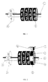
- FIG. 1 represents a conventional wheel meter indicator, the number of wheels depend on maximum reachable value (3), by each turn a wheel gives, the left side one, goes up one digit.
- the right side one is the least weight one, (2).
- FIG. 2 represents an indicator with the possibility of remote reading in line with the invention.
- the right wheel is changed or covered with a substance of two colours BLACK AND WHITE distributed in two areas.
- the relation in size does not vary the working characteristics, but it is better neither of each zones be less than the size of a digit, because it would suppose a faster response in the associated electronic device.
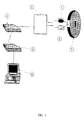
- FIG. 3 represents the diagram of a complete remote reading system as used in the invention
- the receiver of the sensor (1) detects an increase in reflected radiation when the white area passes facing the sensor, what produces an increment of voltage in the receiver (1) which is interpreted as a turn by the electronic device (3), increasing the content of a memory associated to the meter.
- the control center (6) communicates with the electronic device through a modem (4) (5) acceding to that value.
- the electronic device is able to serve various sensors with its associated meters.
- FIG. 4 represents a gas meter of common use in present nets, modified as the invention, for remote reading.
- FIG. 5 represents the meter indicator when is separated from the meter. There exist some kinds of gas meters which use the same type of indicator.
- FIG. 6 represents the same indicator in back view, where we can distinguish the sensor and the two colour wheel.
- FIG. 7 the same figure with the sensor dismantled, in which we can notice the window opened in the casing, and where the sensor must be positioned and fixed.
- FIG. 8 shows another possibility of implementation of the idea, putting the sensor (1), (2) next to one of the wheel faces (bases), near the edge, in place of situating near from the cilindric revolution surface; the mentioned face has two sectors of two colours with high (3) and low (4) absortion (of radiation).
- the object related to the invention is the meter indicator, where, in a part of them, the rotatory wheels are installed FIG. 5.
- the wheel that has the least weight digits (right side one), is replaced by other with identical shape but made in two colours, black and white.
- colours we must not limit to the concept of visible light so that we can use radiation not visible such as infrared, ultraviolet, or even electromagnetic radiation.
- BLACK means that absorves the radiation perfectly and WHITE that reflects it nearly completely.
- the emitter will usually be an infrared LED and the receiver a PHOTODIODE sensible to the radiation, soldered in a little printed circuit and fixing this circuit by a screw to the casing such as in FIG. 6.
- a screw to the casing such as in FIG. 6.
- three conductor wires One for drive the emitter, other to receive the sensor voltage and the third, common to both, is the mesh of the wire that joins the others with the electronic device FIG. 3 (3);if the electronic device associated to the sensor needs four cables, the connection can be to four wires separating emitter and receiver.
- the electronic device FIG. 3 (3) drives the emitter with an intensity matched so that the receiver perfectly detects the radiation reflected by the wheel, when in front of them is the WHITE zone, in case of being in the BLACK zone, no measurable signal is detected.
- the electronic device can drive the emitter with an impulsive signal or a high frequency modulated one so as to produce, when reflected in the WHITE area, a differentiated signal.
- the simplest implementation way is with a continuous driving, shielding from radiation, if necessary, with an opaque painting or changing the casing if it were transparent.
- the two zones BLACK and WHITE repeatedly go in front of the sensor, producing in this one a wave of period equal to the wheel rotation; as we initiate the electronic device with the same value of the mechanical indicator and we track the wave generated by the sensor we have in every moment the value showed by the indicator only counting the periods of the electric wave coming from the sensor, job done by the electronic device.
- the lose of the least significative digit (least weight one) produced by the change of the wheel has usually no importance because it represents hundreths or thousandths of the unit of measure, and it is compensated as turns passes.
- the meter indicator is changed by one modified or made as the invention.
- the original indicator can be modified by painting the least weight wheel with BLACK and WHITE and adding the group emitter-receiver, therefore prepared to be used again. This modification could also be done in the meter without changing the indicator although this could turn out more complex.
- FIG. 5 we can see the modification process of a gas meter.
- the painting of the transparent casing is optional, and necessary only if we want to simplify to the maximum the electronic device functions.
- the device related to the invention has application in any type of mechanical meter which needs remote reading, although the clearest field of application is that of gas, electricity or water nets, due to the next reasons;
Abstract
The invention relates to a remote reading meter. It is comprised of a disc or a drum divided into two zones at its external or peripheral surface, the first zone being made of high absorbing material (black) which absorbs the radiation emited, and the second zone being made of low absorbing material (white) absorbing radiations. At the vicinity of said surface, the sensor is arranged which comprises an emitter and a receiver, and which detects the radiation reflected by the absorbing zone. The frequency of the pulses generated at the receiver is proportional to the consumption or to the rotational velocity of the drum. The emitter-reciver assemby may be substituted by two optical fibres with emitter-receiver at the beginning. The emitter emits at a frequency remote from the light spectrum in order to avoid the interferences of the solar light. The device is connected to a control center in order to evaluate by data processing the consumption generated. The device can be applied to any type of meter. It solves the problem of displacement of a man to read meters.
Description
- The present invention referes to a mechanical meter device, and a procedure of implementation, through which a modification in present mechanical wheel meters will lead to remote reading and automatic reading thereof, giving datas that may be processed in real time with a computer.
The modification can be made during the production process, in meters that have been made, or even in meters in use. - Nowadays various industrial activities such as distribution of gas, water, electricity, automatic vending machines or mass production process, use meters that in most cases go with an indicator formed by wheels which number depends on the maximum value to be reached as in FIG. 1. The operation is such that each wheel has drawn or engraved the numbers from 0 to 9, and each time a wheel turns completely, the left side one moves forward one digit so that the value we can read in the visor is, without considering the least weight digit, the number of turns gived by the right side wheel FIG.1(2), which shows tenths of turn. The total meter value. represents as the case: cubic metres, watthour, screws, etc. and including decimals if necessary.
- These mechanical indicators are simple and reliable enough but have the important obstacle such that, for the reading, it is necessary a meterman to go, see and write the values. This supposes a great cost and risk of error due to the manual reading. In case we talk about nets with a lot of meters, such as gas nets, water nets or electricity nets it is necessary to process the datas to invoice, make statistics, etc. copying them in a computer by a manual or semiautomatic way that converts the process in a slow and expensive one. The results are always refered to behind datas and in case of price changes, as with operation of gas nets, it imply the reading of all meters each week, which is very costly if done manually.
- The invention permits the companies that operate with this kind of nets, (thousands of meters) to have access, in real time, and automatically, to datas, using a computer with a modem that captures and processes them, mixing the datas with their computer applications, to give, e.g. a detailed invoice.
- Due to a modification or implementation technically simple in present meters, is possible to change the present installations, in most cases, without changing all the meter.
- In production process, the cost added to the meter is minimum, making it competitive with digital electronic meters, which are much more expensive ones.
- FIG. 1, represents a conventional wheel meter indicator, the number of wheels depend on maximum reachable value (3), by each turn a wheel gives, the left side one, goes up one digit. The right side one is the least weight one, (2). Through the visor (1) we can see the meter value.
- FIG. 2, represents an indicator with the possibility of remote reading in line with the invention. The right wheel is changed or covered with a substance of two colours BLACK AND WHITE distributed in two areas. The relation in size does not vary the working characteristics, but it is better neither of each zones be less than the size of a digit, because it would suppose a faster response in the associated electronic device. Next to the wheel we put a sensor formed by a radiation emitter (6) and a receiver (7).
- FIG. 3, represents the diagram of a complete remote reading system as used in the invention, the receiver of the sensor (1) detects an increase in reflected radiation when the white area passes facing the sensor, what produces an increment of voltage in the receiver (1) which is interpreted as a turn by the electronic device (3), increasing the content of a memory associated to the meter. The control center (6), comunicates with the electronic device through a modem (4) (5) acceding to that value. The electronic device is able to serve various sensors with its associated meters.
- FIG. 4, represents a gas meter of common use in present nets, modified as the invention, for remote reading.
- FIG. 5, represents the meter indicator when is separated from the meter. There exist some kinds of gas meters which use the same type of indicator.
- FIG. 6, represents the same indicator in back view, where we can distinguish the sensor and the two colour wheel.
- FIG. 7, the same figure with the sensor dismantled, in which we can notice the window opened in the casing, and where the sensor must be positioned and fixed.
- FIG. 8, shows another possibility of implementation of the idea, putting the sensor (1), (2) next to one of the wheel faces (bases), near the edge, in place of situating near from the cilindric revolution surface; the mentioned face has two sectors of two colours with high (3) and low (4) absortion (of radiation).
- In order to the practical implementation of the idea for the invention, it is necessary to distinguish between two distinct situations, according to the production or the modification of meters already made or working. In both cases the object related to the invention is the meter indicator, where, in a part of them, the rotatory wheels are installed FIG. 5. In the production process the wheel that has the least weight digits (right side one), is replaced by other with identical shape but made in two colours, black and white. When refering to colours we must not limit to the concept of visible light so that we can use radiation not visible such as infrared, ultraviolet, or even electromagnetic radiation. In any case, BLACK means that absorves the radiation perfectly and WHITE that reflects it nearly completely. Next to the wheel surface and perpendicular to the same, we put a little electronic circuit formed by an emitter and a receiver. The emitter will usually be an infrared LED and the receiver a PHOTODIODE sensible to the radiation, soldered in a little printed circuit and fixing this circuit by a screw to the casing such as in FIG. 6. From this circuit three conductor wires: One for drive the emitter, other to receive the sensor voltage and the third, common to both, is the mesh of the wire that joins the others with the electronic device FIG. 3 (3);if the electronic device associated to the sensor needs four cables, the connection can be to four wires separating emitter and receiver.
- The electronic device FIG. 3 (3), drives the emitter with an intensity matched so that the receiver perfectly detects the radiation reflected by the wheel, when in front of them is the WHITE zone, in case of being in the BLACK zone, no measurable signal is detected. To avoid interferences coming from outside light, the electronic device can drive the emitter with an impulsive signal or a high frequency modulated one so as to produce, when reflected in the WHITE area, a differentiated signal. Nevertheless, the simplest implementation way is with a continuous driving, shielding from radiation, if necessary, with an opaque painting or changing the casing if it were transparent. In any case the principle of working is the same: as the wheel turns, the two zones BLACK and WHITE repeatedly go in front of the sensor, producing in this one a wave of period equal to the wheel rotation; as we initiate the electronic device with the same value of the mechanical indicator and we track the wave generated by the sensor we have in every moment the value showed by the indicator only counting the periods of the electric wave coming from the sensor, job done by the electronic device. The lose of the least significative digit (least weight one) produced by the change of the wheel, has usually no importance because it represents hundreths or thousandths of the unit of measure, and it is compensated as turns passes. Nevertheless, in certain meters, there exists a wheel which moves this one of less weight and which there has no digit printed, or, as in electricity meters, has a mark to detect turns. In this case, we could use this wheel to the objective exposed, simplifying the implementation; we can also take the idea showed in FIG. 8, where the sensor goes next to one of the bases of the wheel , which goes painted or made in two colour sectors. The advantage that supposes this last possibility - to modify a wheel that does not belong to the mechanical indicator- is that we could substitute the wheel indicator by a display or digital indicator, controlled by the own electronic device FIG.3 which controls the sensor, device that makes the correspondence between turns and units of measure. As the same electronic device is able to service various sensors, we could use the same display and give complete information without excessive cost.
- In case of using the invention with present meters , if possible, the meter indicator is changed by one modified or made as the invention. After that, the original indicator can be modified by painting the least weight wheel with BLACK and WHITE and adding the group emitter-receiver, therefore prepared to be used again. This modification could also be done in the meter without changing the indicator although this could turn out more complex.
- Going on with figures FIG. 4, FIG. 5, FIG.6 and FIG.7 we can see the modification process of a gas meter. The painting of the transparent casing is optional, and necessary only if we want to simplify to the maximum the electronic device functions.
- The device related to the invention has application in any type of mechanical meter which needs remote reading, although the clearest field of application is that of gas, electricity or water nets, due to the next reasons;
- It is possible a better management of the net, because we have real time datas which permit an automatic full invoice, differenciation of high and low consume customers, forecast of consumes, information to dimensionate the nets, etc.
- The meters are usually identical, and in the form of the type mentioned in the invention, what permits a modification or mass production at a lower cost.
- The meters use to be grouped all together in a meters room, what permits that the same electronic device serve all them, simplifying the installation and lowering the cost by meter.
- In case of gas nets, we have made an allowance of an electronic device which serves untill 32 meters, device provided with a microprocessor which samples the sensors and saves in memory the real time datas. In a full installation to a block of buildings, will put one of these type of systems in each meter room, joined all them by four wires, two for communications and the other pair for telefeed, constituting a net that can serve up to 512 meters. In this net, one of the systems has the supply for telefeed and a modem connected to a telephone conventional line so as to give the control center access to datas of all devices. In case of already installed nets, it will be installed an electronic device in each meter room and the indicators will be changed by ones of the invention, with the possibility of reuse as said before.
Claims (11)
- Meter device of remote reading, characterized by having a wheel with its surface covered by two colours, distributed in two areas, or made by two materials, one of them very absorbent (black) for a kind of radiation, and the other very little absorbent (white), next to the wheel is found a sensor constituted by an emitter and a receiver of such radiation, sensor which detects, due to reflection of radiation, when the white zone, in its turn, is passing in front of the sensor. Each turn of the wheel will produce in the receiver a variable tension of the same period as the rotation of the wheel, what permits an electronic device, connected to the sensor by wires, to know, in each moment, the number of periods counted, and this will match the value indicated by the mechanical meter, if we always initiate them with the same value.
- A device as in claim 1, characterized because the emitter and receiver do not go next to the wheel but go in the electronic associated device, two optical fibers join the group emitter-reciver with the two-colour wheel of the meter, the fiber ends go next to the wheel surface, one of the fibers emits radiation and the other receives it. This type of implementation permits the wheel to have a minimal size, as the place of the sensor is used by two optical fiber ends.
- A device as in claims 1 and 2, in which the emitter operates at a frequency far away from luminous spectrum so as to eliminate, as much as possible, the solar interference and conventional light emision interference.
- A device as in claims 1 to 3 characterized because the source of radiation is modulated at a certain frequency or in an impulsive way, so as to the electronic device connected to the receiver be able to discriminate the variable signal from the continuous one, originated from solar light or an artificial external light, avoiding interferences.
- A device as in claims 1 to 4 in which the rotatory wheel, is not painted in the cylindrical revolution surface but in one of the bases, which is divided in two sectors one of each colour. Next to this surface goes the emitter-reciever.
- A device as in claims 1 to 5 characterized by not existing the wheels of the mechanical indicator but a two colour wheel which turns with an angular velocity proportional to the consume to measure; the same electronic device connected to the sensor receiver shows in a display or a screen (LCD, etc) the meter status.
- A device as in claims 1 to 6 in which the wheel has an even number of zones alternating colours, the out frequency of the sensor receiver will be a multiple of two of the turn frequency of the wheel what permits an increase of precision.
- A device as in claims 1 to 7 characterized by the group emitter, receiver, and two-colour rotatory wheel is fully isolated of external light, being the casing opaque, avoiding all kind interferences.
- A device as in claims 1 to 8 in which there is a wheel made of non metallic material wherein the band of one colour is substituted by a metallic material or a metallic ink, and the receiver by a sensor of metal of very little size, saving the emitter and avoiding luminous interferences.
- A production procedure, associated to claim 1, that permits the mechanical wheel indicators of common use to be converted into remote reading meters as claim 1. The procedure is characterized because the least weight wheel is changed or covered by a two-colour substance, and next to the surface a sensor as in claim 1 must be situated fixing it to the casing.
- An application of the device related to claims 1 to 9, characterized by incorporate all electronic circuits which permit remote reading of one or more meters from a control center and the computer process of the datas.
Applications Claiming Priority (3)
| Application Number | Priority Date | Filing Date | Title |
|---|---|---|---|
| ES9501769A ES2112177B1 (en) | 1995-09-08 | 1995-09-08 | REMOTE READING MECHANICAL COUNTER DEVICE. |
| ES9501769 | 1995-09-08 | ||
| PCT/ES1996/000157 WO1997009693A1 (en) | 1995-09-08 | 1996-08-05 | Mechanical meter with remote reading capacity |
Publications (1)
| Publication Number | Publication Date |
|---|---|
| EP0810548A1 true EP0810548A1 (en) | 1997-12-03 |
Family
ID=8291544
Family Applications (1)
| Application Number | Title | Priority Date | Filing Date |
|---|---|---|---|
| EP96925764A Withdrawn EP0810548A1 (en) | 1995-09-08 | 1996-08-05 | Mechanical meter with remote reading capacity |
Country Status (4)
| Country | Link |
|---|---|
| EP (1) | EP0810548A1 (en) |
| AU (1) | AU6616596A (en) |
| ES (1) | ES2112177B1 (en) |
| WO (1) | WO1997009693A1 (en) |
Cited By (6)
| Publication number | Priority date | Publication date | Assignee | Title |
|---|---|---|---|---|
| FR2814545A1 (en) * | 2000-09-26 | 2002-03-29 | Jean Luc Trapant | Digital counter for displaying the amount of air sampled during a sampling period based on an analogue display meter with rotating counter wheels, the rotation of which is optically sensed and used with the digital display |
| DE102009003976A1 (en) * | 2009-01-07 | 2010-07-08 | Hengstler Gmbh | Device for the optical scanning of graduations of a mechanical roller counter |
| CN104913822A (en) * | 2015-07-09 | 2015-09-16 | 彭红军 | Natural light interference resistant intelligent gas meter and gas sampling and detecting method |
| CN105180849A (en) * | 2015-04-15 | 2015-12-23 | 智恒(厦门)微电子有限公司 | Photoelectric counting sensor capable of measuring plurality of objects falling at the same time and with volume measuring function |
| EP3040686A1 (en) | 2014-12-30 | 2016-07-06 | Acotel Group S.p.A. | Device and method for reading a meter |
| CN104157078B (en) * | 2014-08-07 | 2016-08-24 | 河北省水利科学研究院 | IC-card water meter measurement device based on image discriminating |
Family Cites Families (6)
| Publication number | Priority date | Publication date | Assignee | Title |
|---|---|---|---|---|
| GB1410912A (en) * | 1971-09-08 | 1975-10-22 | Counting Instr Ltd | Meter reading systems |
| US4327362A (en) * | 1978-10-23 | 1982-04-27 | Rockwell International Corporation | Meter rotor rotation optical sensor |
| GB8506331D0 (en) * | 1985-03-12 | 1985-04-11 | Eg Technology Ltd | Converting cyclic motion into digital output |
| KR890008726Y1 (en) * | 1987-02-03 | 1989-11-30 | 최혁 | Remote indicating water meter |
| US5045691A (en) * | 1990-01-29 | 1991-09-03 | Sensors Unlimited Inc. | Opto-electronic system for measuring and displaying rotary movement |
| DK134291D0 (en) * | 1991-07-12 | 1991-07-12 | Tim Newlin | SENSOR FOR OPTICAL DETECTION OF CONSUMER INDICATOR INDICATION OF CONSUMPTION |
-
1995
- 1995-09-08 ES ES9501769A patent/ES2112177B1/en not_active Expired - Lifetime
-
1996
- 1996-08-05 WO PCT/ES1996/000157 patent/WO1997009693A1/en not_active Application Discontinuation
- 1996-08-05 EP EP96925764A patent/EP0810548A1/en not_active Withdrawn
- 1996-08-05 AU AU66165/96A patent/AU6616596A/en not_active Abandoned
Non-Patent Citations (1)
| Title |
|---|
| See references of WO9709693A1 * |
Cited By (9)
| Publication number | Priority date | Publication date | Assignee | Title |
|---|---|---|---|---|
| FR2814545A1 (en) * | 2000-09-26 | 2002-03-29 | Jean Luc Trapant | Digital counter for displaying the amount of air sampled during a sampling period based on an analogue display meter with rotating counter wheels, the rotation of which is optically sensed and used with the digital display |
| DE102009003976A1 (en) * | 2009-01-07 | 2010-07-08 | Hengstler Gmbh | Device for the optical scanning of graduations of a mechanical roller counter |
| CN104157078B (en) * | 2014-08-07 | 2016-08-24 | 河北省水利科学研究院 | IC-card water meter measurement device based on image discriminating |
| EP3040686A1 (en) | 2014-12-30 | 2016-07-06 | Acotel Group S.p.A. | Device and method for reading a meter |
| US9712896B2 (en) | 2014-12-30 | 2017-07-18 | Acotel Groups S.P.A. | Device and method for reading a meter |
| CN105180849A (en) * | 2015-04-15 | 2015-12-23 | 智恒(厦门)微电子有限公司 | Photoelectric counting sensor capable of measuring plurality of objects falling at the same time and with volume measuring function |
| CN105180849B (en) * | 2015-04-15 | 2019-11-22 | 智恒(厦门)微电子有限公司 | It is a kind of to be capable of measuring multiple while falling objects and the photoelectricity number sensor with cubing function |
| CN104913822A (en) * | 2015-07-09 | 2015-09-16 | 彭红军 | Natural light interference resistant intelligent gas meter and gas sampling and detecting method |
| CN104913822B (en) * | 2015-07-09 | 2018-07-13 | 彭红军 | The intelligent gas meter and combustion gas sample detecting method of anti-natural light interference |
Also Published As
| Publication number | Publication date |
|---|---|
| AU6616596A (en) | 1997-03-27 |
| WO1997009693A1 (en) | 1997-03-13 |
| ES2112177A1 (en) | 1998-03-16 |
| ES2112177B1 (en) | 1998-11-16 |
Similar Documents
| Publication | Publication Date | Title |
|---|---|---|
| US4670737A (en) | Method of initializing an optical encoder | |
| CN101308550B (en) | Counting digit wheel radial transmitting photoelectric direct-reading apparatus of long distance transmitting meter | |
| EP0810548A1 (en) | Mechanical meter with remote reading capacity | |
| EP0553332B1 (en) | Remote meter reading | |
| US5089771A (en) | Reading device for a watt-hour meter | |
| US5495238A (en) | Induction watt-hour meter non-intrusive and concealed pulse initiator | |
| US4588982A (en) | Optical shaft encoder | |
| CA2001635C (en) | Analogic digital optoelectromagnetic counting system for fluids | |
| US5130641A (en) | Eddy wheel edge sensor | |
| EP0547879B1 (en) | Meter output devices | |
| GB2148565A (en) | Monitoring devices | |
| US3878391A (en) | Radiometric pulse initiator having a reflective patterned drum | |
| AU8027698A (en) | Improvements in, or relating to, electricity consumption meters | |
| JPH06508924A (en) | A sensor that optically detects the movement of the moving parts of a consumption meter that visually displays consumption. | |
| CA1247209A (en) | Method and apparatus for detecting tampering with a meter having an encoded registered display | |
| KR100306217B1 (en) | Automatic remote measuring system for watt-hour meter | |
| US3662368A (en) | Telemetering system having a continuously monitoring encoder | |
| CN2459715Y (en) | Counter reading out device for flow meter | |
| CN2324545Y (en) | Number transfer electric meter | |
| CN2426602Y (en) | Digital dial with photoelectric digit identifying sign | |
| CN2422689Y (en) | Electronic digital reading mechanical runner counter | |
| CN2422688Y (en) | Automatic code disc direct reader | |
| CN201213002Y (en) | Radial direction transmission photoelectric direct-reading apparatus for metering wheel of remote transmission gauge | |
| CN100449271C (en) | Automatic code-disc direct read device | |
| CN2324546Y (en) | Electronic counting electric meter |
Legal Events
| Date | Code | Title | Description |
|---|---|---|---|
| PUAI | Public reference made under article 153(3) epc to a published international application that has entered the european phase |
Free format text: ORIGINAL CODE: 0009012 |
|
| 17P | Request for examination filed |
Effective date: 19970509 |
|
| AK | Designated contracting states |
Kind code of ref document: A1 Designated state(s): CH DE GB LI |
|
| STAA | Information on the status of an ep patent application or granted ep patent |
Free format text: STATUS: THE APPLICATION IS DEEMED TO BE WITHDRAWN |
|
| 18D | Application deemed to be withdrawn |
Effective date: 20010301 |