EP0810153A1 - Article binding method and apparatus - Google Patents
Article binding method and apparatus Download PDFInfo
- Publication number
- EP0810153A1 EP0810153A1 EP96902457A EP96902457A EP0810153A1 EP 0810153 A1 EP0810153 A1 EP 0810153A1 EP 96902457 A EP96902457 A EP 96902457A EP 96902457 A EP96902457 A EP 96902457A EP 0810153 A1 EP0810153 A1 EP 0810153A1
- Authority
- EP
- European Patent Office
- Prior art keywords
- tying
- tying material
- twisting
- spindle
- end portion
- Prior art date
- Legal status (The legal status is an assumption and is not a legal conclusion. Google has not performed a legal analysis and makes no representation as to the accuracy of the status listed.)
- Granted
Links
Images


Classifications
-
- B—PERFORMING OPERATIONS; TRANSPORTING
- B65—CONVEYING; PACKING; STORING; HANDLING THIN OR FILAMENTARY MATERIAL
- B65B—MACHINES, APPARATUS OR DEVICES FOR, OR METHODS OF, PACKAGING ARTICLES OR MATERIALS; UNPACKING
- B65B13/00—Bundling articles
- B65B13/02—Applying and securing binding material around articles or groups of articles, e.g. using strings, wires, strips, bands or tapes
- B65B13/04—Applying and securing binding material around articles or groups of articles, e.g. using strings, wires, strips, bands or tapes with means for guiding the binding material around the articles prior to severing from supply
-
- B—PERFORMING OPERATIONS; TRANSPORTING
- B65—CONVEYING; PACKING; STORING; HANDLING THIN OR FILAMENTARY MATERIAL
- B65B—MACHINES, APPARATUS OR DEVICES FOR, OR METHODS OF, PACKAGING ARTICLES OR MATERIALS; UNPACKING
- B65B13/00—Bundling articles
- B65B13/18—Details of, or auxiliary devices used in, bundling machines or bundling tools
- B65B13/24—Securing ends of binding material
- B65B13/28—Securing ends of binding material by twisting
- B65B13/285—Hand tools
-
- B—PERFORMING OPERATIONS; TRANSPORTING
- B65—CONVEYING; PACKING; STORING; HANDLING THIN OR FILAMENTARY MATERIAL
- B65B—MACHINES, APPARATUS OR DEVICES FOR, OR METHODS OF, PACKAGING ARTICLES OR MATERIALS; UNPACKING
- B65B13/00—Bundling articles
- B65B13/18—Details of, or auxiliary devices used in, bundling machines or bundling tools
-
- E—FIXED CONSTRUCTIONS
- E04—BUILDING
- E04G—SCAFFOLDING; FORMS; SHUTTERING; BUILDING IMPLEMENTS OR AIDS, OR THEIR USE; HANDLING BUILDING MATERIALS ON THE SITE; REPAIRING, BREAKING-UP OR OTHER WORK ON EXISTING BUILDINGS
- E04G21/00—Preparing, conveying, or working-up building materials or building elements in situ; Other devices or measures for constructional work
- E04G21/12—Mounting of reinforcing inserts; Prestressing
- E04G21/122—Machines for joining reinforcing bars
- E04G21/123—Wire twisting tools
Definitions
- the present invention relates to a tying method and a tying apparatus therefor for automatically tying various articles by linear tying materials, such tyings including a tying of bar-like articles such as reinforcements, pipes and various other articles, a tying of heat insulating sheets wound about, for example, pipes, air conditioning ducts or the like, a tying of bag openings, a tying of a single article such as repair of fishing nets, medical binding or sewing-up, etc.
- linear tying materials such tyings including a tying of bar-like articles such as reinforcements, pipes and various other articles, a tying of heat insulating sheets wound about, for example, pipes, air conditioning ducts or the like, a tying of bag openings, a tying of a single article such as repair of fishing nets, medical binding or sewing-up, etc.
- tying machines for automatically tying reinforcements.
- tying machines thus proposed suffer from a problem in that any of these machines is complicated in construction, is heavy, is high in manufacturing cost and is inconvenient in handling.
- a single iron wire is drawn out of a bobbin and wound around a joined portion of reinforcements with that single iron wire to bind the joined portion, and therefore it is necessary to wind the object several times in order to provide a firm tying.
- a long tying material is required as compared with the tying through manual operation, resulting in a higher cost of tying materials.
- the single wire tends to be ruptured, and a strong tying force is hard to obtain as compared with the typing through manual operation for effecting the tying after the iron wire is bent into two parts to form a double configuration.
- the present inventors have previously proposed a method and an apparatus therefor for automatically bending a continuous linear tying material drawn out of a bobbin or the like to form two wires to provide powerful tying by a single winding (International Application International Laid-Open Publication No. WO95/05313).
- the tying method and the tying apparatus therefor proposed as described above are further improved by the present invention. It is an object of the present invention to provide a typing method and a tying apparatus therefor which is simple in mechanism, is less in the number of parts, is light-weight, is less in load imposed on a motor to prolong the service life of the motor, and can firmly and positively tie articles by a short tying material as compared with prior art.
- the method of tying articles according to the present invention for achieving the aforementioned object is characterized by comprising: a tying material bending step of holding a substantially extreme end portion of a continuous linear typing material being delivered by tying material holding means to apply a resistance to form a start point at which the tying material is bent into a substantially U-shape; an encompassing and guiding step of guiding said tying material around an article to be tied while bending the former into a substantially U-shape; a tying material cutting step of cutting a rear end portion of said tying material from a continuous wire at a suitable time; and a twisting step of twisting a bent extreme end portion and a rear end portion on the other side of said tying material together to band the article to be tied, said bent extreme end portion and said rear end portion on the other side of said tying material being twisted together while said tying material holding means and said twisting means are rotated integrally.
- the aforementioned object can be further achieved, in the method of tying articles comprising the above-described steps, by employing a method characterized in that a tying material is fed to said tying material holding means from a direction crossing an axis of a spindle to have an extreme end portion engaged with said tying material holding means; a method characterized in that a bent extreme end portion and a rear end portion on the other side of a tying material are twisted together each other while said tying material holding means and said twisting means are integrally displaced in an axial direction of a spindle; a method characterized in that a bent extreme end portion and a rear end portion on the other side of a tying material are twisted together each other while said tying material holding means and said twisting means are integrally displaced towards articles to be tied; more preferably, all the methods described above.
- the bent extreme end portion of the tying material moved out of the encompassing and guiding means is automatically guided to a position in engagement with the twisting means whereby the bent extreme end portion can be positively engaged with the hook.
- said tying material holding means is displaced toward the articles to be tied integral with the tying material twisting means during the twisting step to thereby firmly band the articles to be tied.
- the movement of the tying material holding means and the tying material twisting means toward the articles to be tied means that the engaging position of these means with the tying material is displaced toward the articles to be tied so that the distance with respect to the articles to be tied comes near; and that the displacement in the axial direction of the spindle means that these means are oscillated and displaced so that the engaging position with respect to the tying material comes close to the spindle axis.
- said tying material holding means and said twisting means are provided on said spindle body so that they can be displaced toward the articles to be tied as the twisting progresses, and more preferably, said tying material holding means and said twisting means are provided on an oscillating member provided on said spindle body in an oscillating manner.
- Said tying material holding means is formed from a groove-like engaging portion in which fitted is a tying material provided at a substantially extreme end portion of said oscillating member, and said tying material twisting means is formed from a hook provided adjacent to said engaging portion.
- said twisting means can be provided on said oscillating member in an oscillating manner so as to be oscillated positively in a direction of a bent extreme end portion of a tying material from said oscillating member so as to come engagement with the bent extreme end portion of the tying material.
- a fixed member for rotatably holding said spindle body is formed with a tying material guide hole for guiding said tying material in a direction crossing a spindle axis, said spindle body being formed with a tying material extending-through hole in communication with said tying material guide hole to cause the tying material to extend through in a direction crossing the spindle axis.
- the tying material is held by said tying material holding means in a direction crossing the spindle axis whereby engaged rear ends of the tying material can be positively twisted together without requiring a special biasing member or the like.
- said cutting means is formed by relative rotational movement of said tying material guide hole and said tying material extending-through hole, it is not necessary to provide a special cutter and cutter driving means, and the number of parts can be reduced.
- Said spindle body is provided so as to be displaced toward the articles to be tied as the twisting progresses and comprises a spindle rotated and driven by a main motor and a spindle extreme end portion pivotally mounted on the extreme end thereof. More preferably, said oscillating member is provided at the extreme end portion of said spindle extreme end member so that as said spindle body is displaced toward the articles to be tied as the twisting progresses, said spindle extreme end member oscillates so as to reduce the rotational radius of said twisting means.
- the main motor and a tying material feed motor need not be separated but for example, they can be connected each other by a clutch mechanism so that the tying material feed means and the twisting means are driven by a single motor.
- another tying apparatus comprises a tying material bobbin mounting frame portion, a driving control portion, a tying mechanism portion, an encompassing and guiding portion and a tying material cutting portion, said driving control portion comprising a tying material feed motor, a main motor for rotating and driving a spindle body of said tying mechanism portion, and a control circuit portion for controlling said tying material feed motor and said main motor, said driving control portion being characterized by capable of being integrally detached from said tying material bobbin holding portion and said tying mechanism portion, a worn driving control portion capable of being replaced for use.
- Still another tying apparatus comprises a tying material feed motor, tying material feed means rotated and driven by said tying material feed motor, a main motor, and a tying mechanism portion having a hook rotated and driven by said main motor, characterized in that said apparatus is separated into at least a tying apparatus body having said tying mechanism portion and at least a separate casing body having said tying material feed motor, and a tying material is fed from said separate casing to the tying mechanism portion of said tying apparatus body by the tying material feed motor held on said separate casing body.
- the tying operation can be carried out by manually holding only the small and light-weight tying apparatus body and the fatigue of the tying operation can be relieved and the operation can be carried out comfortably.
- the aforementioned main motor can be provided on either said tying apparatus body or said separate casing body.
- a rotating torque is transmitted to said tying mechanism portion through a flexible shaft.
- Said tying material feed means can be also provided on either the separate casing body or the tying apparatus body.
- the tying material feed means is provided on the tying apparatus body, it is rotated and driven through the flexible shaft from the tying material feed motor provided on the separate casing body, and the tying material can be drawn out of the tying material bobbin held on the separate casing body on the side of the tying apparatus body to prevent a bend of the tying material halfway and to enable supplying of a tying material in a lighter and better way.
- a tying apparatus 1 comprises a tying material bobbin holding portion 2, a driving control portion 3, a tying mechanism portion 4, and an encompassing and guiding portion 5. These portions can be detachably assembled simply. The detailed construction of these portions will be described below.
- Tying material bobbin holding portion 2 Tying material bobbin holding portion 2
- the tying material bobbin holding portion 2 combines a rear handle 6 and a battery casing 7 so as to rotatably hold a tying material bobbin 8.
- the tying apparatus according to the present embodiment is provided with two handles, i.e., the rear handle 6 and a front handle 24 described later.
- a rear trigger switch 9 and a front trigger switch 25 are provided at a base portion of the rear handle and at a base portion of the front handle 24, respectively, so that the tying operation can be done by any of the handles.
- the front handle 24 and the rear handle 6 can be held by one hand and by the other hand, respectively, whereby the tying operation can be done comfortably just like the rifle shooting style.
- the tying operation can be also done in the state where a rear end porion 10 of the tying material bobbin holding portion is suspended on a shoulder and only the front handle is held, and the tying operation can be done very comfortably.
- the rear end portion 10 is slightly projected rearward from the base portion of the rear handle so that the rear end portion of the tying material bobbin holding portion is easily suspended.
- the driving control portion 3 has a tying material feed motor 15, a main motor 16 and a control circuit portion 17 provided with a microcomputer chip mounted within a motor casing 18, which can be integrally mounted and removed from the tying material bobbin holding portion 2 by means of connection bolts 14.
- the tying material feed motor 15 and the main motor 16 are integrally provided with reduction gears 19 and 20, respectively, and the reduction gear 19 is provided at the output shaft end with a tying material feed roller 21 as tying material feed means, and an output shaft 22 of the reduction gear 20 projects forwardly of the motor casing 18 so that a spindle supported by bearings on the bearing casing of a tying mechanism portion described later can be mounted.
- the tying material feed roller 21 holds a tying material between the former and the other driven roller not shown so as to feed the tying material.
- the tying material is guided to a tying material guide pipe 23 provided so as to extend through the motor casing and reach the bearing case of the tying mechanism portion and is fed to the tying mechanism portion 4.
- the driving control portion which is subjected to most severe consumption can be integrally mounted and removed, for example, when the motor is broken or reaches a predetermined service life, only the driving control portion can be replaced with a new one simply for use.
- a small motor which has a long life capable of withstanding about 2,000,000 times of tying has appeared.
- the driving control portion can be also integrally replaced, when the motor is replaced, a program of a microcomputer can be changed according to the connection to a control circuit panel and the performance of the motors, and thus, the motor can be replaced very quickly and positively.
- the type mechanism portion 4 constitutes the most characteristic portion of the present invention, the embodiment of which is clearly shown in an enlarged scale in FIGS. 2 and 3.
- the tying mechanism portion 4 is held by a spindle casing 31 detachably mounted by means of a connection bolt 30 on the front surface of the motor casing 18 of the driving control portion 3, and comprises, as main members, a bearing casing 32 secured to the spindle casing, a spindle 33, and an oscillating member 43.
- a tying material guide hole 38 in which an end of the tying guide pipe 23 is fitted is obliquely formed from the lower end toward substantially the axial direction of the spindle.
- the spindle 33 has its shaft portion 35 rotatably supported by bearings in the bearing casing 22 through bearings 36, and a sleeve coupling hole 37 in which the output shaft 22 of the main motor 16 is fitted is formed in the center portion of the shaft portion.
- a flange 39 is formed forwardly, and the aforesaid flange is formed with a tying material extending-through hole 40 which communicates with the tying material guide hole 38 formed in the bearing casing 32 so as to guide a tying material w being fed by the tying material feed motor 15 obliquely upwardly crossing the spindle axis from the lower portion.
- an inclined guide surface 41 is projected substantially in a central portion of a flange surface in order to guide the tying material having extended through the tying material extending-through hole 40 crossing the spindle axis
- the flange 39 is provided through a shaft 42 with an oscillating member in an oscillating manner.
- An extreme end portion on the rear surface side of the oscillating member has a folded back member 44 folded back rearward having enough clearance for a tying material to be fitted to form a groove-like engaging portion 45 on which an extreme end of a tying material having been guided by the inclined guide surface 41 impinges and comes into engagement therewith.
- a hook 46 constituting twisting means in the folded back member 44 is provided so that a release portion at the extreme end thereof is vertical with respect to a paper surface in FIG. 2.
- an inclined guide surface 47 for automatically guiding a bent extreme end portion of a tying material guided around an article not to be tied through an encompassing guide described later so as to cause the former to engage the hook 46.
- the inclined guide surface 47 is formed to have enough length to cross the extreme end portion of the spindle.
- the oscillating member 43 is normally biased by a spring 44 fitted in the shaft 42 so as to be maintained at a substantially vertical position as shown in FIG. 2.
- the spring 44 is formed by two springs, i.e., a weak spring which is pressed by a tying material so that the oscillating member is urged by a weak spring pressure till the oscillation in a predetermined range, and a strong spring which exerts with respect to the oscillation in excess of a predetermined range.
- the encompassing and guiding portion 5 comprises a pair of encompassing guides 55 1 , 55 2 closably pivotally mounted on the extreme end of the tying mechanism portion 4 by means of hinge pins 54 1 , 54 2 and is normally in an open state biased by a spring as shown by the broken line in FIG. 1.
- the tying apparatus 1 is pressed against articles to be tied through an opening whereby articles to be tied engaging members 56 1 , 56 2 formed on the encompassing guides 55 1 , 55 2 is pressed by the articles to be tied so that the encompassing guides are closed.
- Both encompassing guides are in the form of a continuously substantially semi-oval in their closed state so that articles to be tied a can be positioned inwardly of the encompassing guides.
- the encompassing guide has a substantially U-shape or V-shape in section whose inside is opened, so that a tying material externally of a tying material to be fed while being folded into a substantially U-shape is moved along the guide surface at the bottom thereof, whereas an internal tying material is stretched internally of the opening, at least a part of which comes in direct contact with the articles to be tied a and is guided thereby.
- both the encompassing guides are opened and closed, one encompassing guide can be fixed. Alternatively, the encompassing guides may be automatically opened and closed by suitable actuators.
- the tying apparatus is constructed as described above.
- the tying apparatus is automatically actuated in accordance with a preset program by pressing the trigger switch 9 or 25.
- a battery as a driving power source is encased in a battery casing for convenience of carrying, it is to be noted of course that an external power source may be employed so as to supply an external power.
- encompassing guide 55 In the state where the encompassing guide 55 is opened as shown in the imaginary line in FIG. 1, when the article to be tied engaging member 56 is pressed against the outer peripheral portion of the articles a to be tied , encompassing guide 55 rotates so that the articles to be tied assumes a position of the inner peripheral portion of the encompassing guide as indicated by the solid line in FIG. 1.
- the trigger switch 9 or 25 is depressed, whereby the tying material feed motor 15 is driven and the tying material feed roller 21 rotates to start the feeding of the tying material.
- the spindle 33 stops with the tying material extending-through hole 40 located so as to be positioned on the extension of the tying material guide hole 38 formed in the bearing casing.
- the tying material w delivered from the winding bobbin 8 is guided by the tying material guide pipe 23 and is fitted in the tying material guide hole 38 (FIGS. 1 and 2).
- the tying material is further guided to the inclined guide surface 41 in a direction crossing the spindle axis extending through the tying material extending-through hole 40, and the substantially extreme end thereof impinges upon the front surface wall of the oscillating member 43 and slips along the surface thereof into engagement with the engaging portion 45.
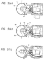
- the oscillating member is pressed by the feeding force thereof and rotate counterclockwise in the figure (FIG. 4(a)).
- the tying material w to be delivered is gradually folded, in its extreme end portion, into a substantially U-shape as shown in FIG. 4(b) by the feeding force thereof to form a start point of forming two lines.
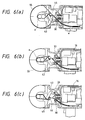
- the tying material feeding motor is reversely rotated to pull the tying material in a reverse direction whereby the loop is stopped at the hook, and the tying material is completely disengaged from the guide surface of the encompassing guide to assume a tense state (FIG. 6(b)).
- the proximal end portion of the tying material is also in a state position in the range of rotation of the hook.
- the main motor is rotated counterclockwise from the aforesaid state whereby the spindle 33 rotates.
- the tying material passes through the tying material extending-through hole 40 passing through the tying material guide hole of the fixed bearing casing 32, a relative positional deviation occurs between the tying material guide hole and the tying material extending-hole due to the rotation of the spindle to exert a shearing force on the tying material, and peripheral edges of both the holes constitute a cutting edge to cut the tying material easily (FIG. 6 (c)).
- the tying material extending-through hole is formed into a spiral slot having an inclined surface with respect to the axis. Accordingly, the tying material can be cut by a weak force.
- the engaging portion 45 as tying material extreme end holding means provided integral with the oscillating member 43 mounted on the spindle and the hook 46 also rotate, and in that state, the twisting progresses.
- the twisting can be made in the state where the twisting center coincided with the spindle axis, and the twisting can progress till a clearance with respect to the articles to be tied a disappears. Accordingly, the articles to be tied can be firmly tied to overcome the disadvantages of prior art.
- the hook and the engaging portion are very close to each other in position, the hook is present on the side of an escape groove of the engaging portion, and they are rotated integrally, the end of the tying material engaged with the engaging portion gradually moves toward the escape groove as the twisting progresses and is automatically disengaged from the engaging portion. Therefore, no inferior disengagement occurs even if a disengaging mechanism is not provided in particular (FIG. 7).
- a disengaging mechanism is not provided in particular (FIG. 7).
- termination of tying is automatically detected.
- the folded portion of the tying material is simply disengaged and the tying terminates. In this state, when the tying apparatus is pulled this side, the encompassing guide 55 is opened to remove it from the peripheral portion of the articles a to be tied. The operation can be quickly shifted to next mode of operation.
- Reinforcements 80 1 and 80 2 can be tied as shown in FIG. 8(a) in the procedure as described above.
- the tying can be carried out by an extremely short tying material as compared with that of the conventional tying apparatus. This is very effective for saving the tying materials. Moreover, fastening can be also done.
- the hook is secured to the oscillating member.
- the hook is provided on the oscillating member so as to be oscillated greatly, for example, as twice as the amount of oscillation of the oscillating member by a suitable transmission mechanism such as a gear
- the hook can be positively moved to a position in engagement with the folded extreme end portion to provide more positive engagement.
- the hook is not necessarily secured to the oscillating member but may be designed to be moved freely.
- the termination of tying is automatically detected by applying a predetermined torque to the spindle, and the spindle is automatically reversely rotated and is disengaged from the folded portion of the tying material
- the present invention is not limited thereto but the hook is rotated in the same direction as it is and a torque in excess of a predetermined value is applied to the spindle whereby the tying material can be torn off from the neighborhood of the folded portion and the hook can be naturally removed from the tying wire.
- the tying mode in case of being tied in such a manner as described is shown in FIG. 8(b).
- the winding bobbin is supported on the tying material bobbin holding portion, it is to be noted that the winding bobbin, the driving control portion and the like may be placed at a position separately from the tying apparatus body, or they can be carried on the waist by a band or the like to draw therefrom.
- one tying material is drawn out of one winding bobbin, which is folded into two wires, and the tying is carried out by one winding of the two wires
- two winding bobbins may be mounted to simultaneously draw two tying materials together, which are folded to provide one winding comprising four wires, and further, one winding tying with the number of tying materials more than the above can be made.
- the number of tying materials is increased whereby even if a diameter of each tying material is made small, the strength can be enhanced, and a flexibility can be increased to reduce the curvature of the encompassing guide, thus further miniaturizing the tying apparatus.
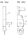
- the front handle is provided at the lower side of the driving control portion, the front handle is not necessarily limited to the aforesaid position but as in a tying apparatus 64 shown in FIGS. 9(a) and (b), a front handle 66 can be provided sideways of a motor casing 65 of the driving control portion, and a suitable position can be selected. Since other structures of the tying apparatus shown in FIG. 9 are similar to those of the previous embodiments, detailed description is omitted.
- the battery casing 7 is mounted on the apparatus body, it is to be noted that it is convenient if a design is made so as to suitably select, according to the situation of an operator, a case where a battery casing is detachably mounted on the apparatus body and is mounted on the body, or a case where for example, a battery casing is supported on the waist of an operator and is connected to the body through a cable from the waist. In this case, preferably, the battery case and the apparatus body are always linked through the cable in order to prevent inferior contact.
- the encompassing guide receives a high resistance from the tying material to be opened in order to guide the tying material around the articles to be tied.
- a locking mechanism which is automatically locked to impede the opening of the encompassing guide in the case where the encompassing guide encases therein articles to be tied.
- rollers are provided outwardly of one of the encompassing guides in order to allow the encompassing guides to move in easily.
- the tying material is fed from the lower porion so as to cross the spindle axis, it is to be noted that such is not always necessary but for example, even if the tying material is fed by the guiding mechanism in a direction parallel with the spindle axis, similar effects can be obtained.
- the tying material bobbin holding portion, the driving control portion, the tying mechanism and the encompassing and guiding portion are connectable each other, it is to be noted that an embodiment is not always limited to the above-described embodiment but for example, a body frame is formed, and a part or whole of the aforementioned portions can be detachably mounted on the body frame in a cassette system, and in addition, the whole body can be integrally formed.
- the tying apparatus is not always limited to a portable type but for example, a power source and a control portion can be provided outside, or a tying material bobbin can be largely provided outside and mounted on an operating robot.
- the tying apparatus of the present invention exhibits a great effect in tying and securing reinforcements in the preparation operation as shown in FIG. 8.
- articles to be tied are not limited to reinforcement but are also useful for, for example, a tying of articles to be tied such as bar-like articles and pipes, and a tying of a single article to be tied such as a tying of an opening of a bag, and a tying and securing of heat insulating sheets wound about pipes or ducts.
- tying apparatus body is super-miniaturized and tying materials are selected, it can be also applied to an apparatus for performing medical tying such as sewing and connection after operation of human being and animal.
- the present tying apparatus can be applied to tying of various kinds of articles if the latter can be tied.
- FIGS. 10 to 17 show another embodiment of the tying apparatus according to the present invention.
- FIGS. 10 to 13 show another embodiment of the tying mechanism portion of the tying apparatus according to the present invention.
- the tying mechanism portion in the present embodiment is similar to that of the previous embodiment in fundamental tying method but unlike the previous embodiment, the present embodiment is characterized in that a spindle body is displaced along the axis as the twisting progresses.
- reference numeral 80 designates a main motor
- 81 designates a sleeve coupling.
- a spindle 83 is connected to an output shaft 82 of the main motor axially displaceably through the sleeve coupling.
- An extreme end member 85 is pivotally mounted by a pin 86 in an oscillating manner on the extreme end portion of the spindle 83, the extreme end member 85 being supported on a sleeve 87 rotatably supported by bearings on a bearing casing 84.
- the extreme end member 85 can be slidably moved axially with respect to the sleeve 87 but can be rotated integral with the sleeve 87.
- the sleeve 87, the extreme end member 85 and the spindle 83 constitute a spindle body.
- an inclined surface 88 for reducing a rotational radius of a hook which performs a function of reducing a rotational radius of a hook as the twisting progresses.
- the spindle 83 is biased leftward in the figure by means of a spring 91 provided between a fixed member 89 secured to the body casing and a flange 90 secured to the spindle so as to return the hook to its initial position.
- a guide surface 97 for guiding a tying material to an engaging portion while being crossed with an axis of a spindle and is provided with a bent extreme end piece 92.
- An oscillating member 93 is pivotally mounted by a pin 94 in an oscillating manner on the bent extreme end piece 92.
- the oscillating member 93 is provided with an engaging portion as tying material holding means with which an extreme end portion of a tying material engages to bend it into a U-shape, and a hook 95.
- the tying mechanism portion in the present embodiment is constructed as described above, and the operation thereof will be described with reference to FIGS. 10 to 13. It is to be noted that since the fundamental twisting operation is similar to that of the previous embodiment, only the characteristic operation of the present embodiment will be described.
- FIG. 10 shows the state where the hook 95 is at an original position before the tying operation starts.
- the tying material delivered passes through a tying material guide hole 96 formed in the bearing casing 84, is guided to a guide surface 97, and impinges upon the guide surface of the oscillating member 93.
- the extreme end portion thereof comes in engagement with the engaging portion whereby the oscillating member 93 is oscillated forward (clockwise in FIG. 10(b)) about the pin 94 by the feeding force of the tying material, and is maintained at a position where the hook can be engaged with the bent extreme end portion of the tying material being guided via the encompassing guide, as shown in FIG. 11.
- the hook rotates into engagement with the bent extreme end portion of the tying material w (FIG. 11(a)) and the tying material is reversely fed whereby the hook is subjected to tension in a direction of arrow in FIG. 12 to compress the spring 91 so that the spindle moves in a direction of arrow (FIG. 12), in which state the twisting starts.
- the hook is subjected to a force to be gradually pulled in the direction of articles to be tied, and therefore the spring 91 is further compressed and the spindle 83 moves toward the articles to be tied.
- the extreme end member can be oscillated about the pin 86 by a clearance between the inclined surface and an extreme end edge of the sleeve.
- the extreme end member is inclined to gradually reduce the twisting radius so that the engaging point between the articles to be tied and the hook assumes a state to be positioned on the twisting center line, in which state the twisting progresses to the end (FIG. 13).
- the twisting As described above, as the twisting progresses, the hook moves toward the articles to be tied, and the twisting can be made in the state where the rotational radius of the twisting is gradually reduced so that the engaging point assumes a position on the twisting center line. Therefore, the twisting can be made without occurrence of excessive conical motion in the twisting proximal end during the progress of twisting. It is possible to progress the twisting successfully till a clearance with respect to the articles to be tied disappears without fatigue of the tying material.
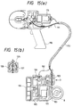
- FIG. 14 shows another embodiment of the tying apparatus according to the present invention.
- a winding bobbin, a tying material feed motor and a control portion are separated from the tying apparatus body to provide a separate casing.
- the separate casing is carried on the waist or the like by a band, as shown in FIG. 18, from which a tying material is drawn whereby the tying apparatus body held by hands can be light-weighted, and the tying operation can be carried out more comfortably and efficiently.
- reference numeral 100 designates a tying apparatus body which is held by hands to carry out a tying operation.
- a tying mechanism portion is substantially similar to that of the previous embodiment, but a tying material feed motor 101 is separated and is encased in a separate casing body 102 which can be carried on the waist while being mounted on a band or the like not shown.
- the tying apparatus body 100 comprises a main motor 115, a tying mechanism portion 116, an encompassing and guiding portion 117, and a handle 119 having a trigger switch 118.
- the separate casing body 102 comprises a tying material bobbin holding portion 103 for rotatably holding the tying material bobbin 8, a battery casing 104 for encasing therein a battery as a power source portion, and a control circuit portion 105.
- tying material feeding means 106 is provided on the tying apparatus body 100 to transmit a torque of the tying material feed motor 101 to the tying material feeding means 106 through a flexible shaft 107.
- the tying material feeding means 106 has a mechanism in which as shown in FIG. 14(b), a tying material is held between a drive gear 108 and a driven gear 109 to deliver the tying material by means of a frictional force of the drive gear, being transmitted to the drive gear through a bevel gear 110 provided on the end of the flexible shaft 107.
- tying material feeding means 106 can be detachably mounted together with its casing on the apparatus body as shown so that when a roller is damaged, only that part can be replaced simply. This is also true for the case of an embodiment shown in FIG. 15.
- tying material feeding means 125 is detachably mounted on a separate casing 126.
- the tying material w passes, between the separate casing 102 and the tying machine body 100, through a flexible guide tube 111.
- the guide tube passes through a large diameter flexible pipe 113 collectively together with the flexible shaft 107 and a power source/signal cable 112, and therefore, successful feeding can be obtained without occurrence that it is bent small halfway of feeding or is entangled with the flexible shaft or the power source/signal cable.
- the tying material feeding means 106 is present in the tying apparatus body. Therefore, the tying material is pulled out on the side of the tying apparatus body, and is not bent halfway and can be fed satisfactorily with less resistance.
- the tying material feeding means is not limited to the configuration comprising a pair of gears, but suitable means such as a belt system shown in FIG. 15(b) and a system having plural pairs of feed gears shown in FIG. 17 described later can be employed.
- the separate casing body 102 is constructed such that a tying bobbin holding portion, a tying material feed motor, a control circuit portion and a battery casing are individually separatably assembled. For example, when the tying material feed motor or the tying material feeding means is consumed, only the consumed one can be replaced for use.
- a battery is used as a power source, it is to be noted of course that a commercial power can be also used, in which case a commercial power adapter can be connected to the power source portion.
- the tying material feed motor, the tying material bobbin, the battery and the control circuit portion are encased in the separate casing body and separated from the tying apparatus body. Therefore, the tying apparatus can be constructed to be very small and light weight. Since the separate casing is attached to the waist or the like for operation, the tying apparatus body held by hands is very light weight, and even women or children can perform the tying operation comfortably. In this case, it is of course that the tying mechanism can be applied to not only the tying machine in the above-described embodiment but also a tying machine having a tying mechanism of other types.
- a spindle 120 is provided with an origin producing cam 121 rotated integral with the spindle, and a detected portion provided at a specific position of an outer peripheral surface of the origin producing cam 121 is detected by an origin sensor 122 provided at a fixed position of the tying apparatus body whereby an origin angle position of a hook 123 can be detected.
- an origin sensor 122 provided at a fixed position of the tying apparatus body whereby an origin angle position of a hook 123 can be detected.
- FIG. 15 shows a modified example of the embodiment shown in FIG. 14, which example is different from the previous embodiment in that tying material feeding means 125 is mounted on a separate casing 126.
- the tying material feeding means 125 in the present embodiment is composed of a pair of feed belts comprising a drive feed belt 127 and a driven feed belt 128 in order to increase a feeding force. Since other structures are similar to those of the embodiment shown in FIG. 14, the same reference numerals are applied to the same members, and a detailed description is omitted.
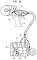
- FIG. 16 shows a further modified example of the embodiment shown in FIG. 14, in which example, a main motor 130 is also separated from a tying apparatus body 131 and encased in a separate casing body 132 so as to rotate and drive the spindle of the apparatus body through a flexible shaft 155. Accordingly, in the case of the present embodiment, the tying apparatus body 131 is further light-weighted. Since other structures are similar to those of the embodiment shown in FIG. 14, the same reference numerals are applied to the same members, and a detailed description is omitted.
- FIG. 17 shows another embodiment of the tying material feeding means.
- Tying material feeding means 135 in the present embodiment is so designed as to feed a tying material by two pairs of gears in order to further increase a feeding force as compared with the case of the pair of gears shown in FIG. 14(b).
- reference numeral 136 designates a gear rotated and driven by a tying material feed motor; 137, 137', drive gears meshed with the first mentioned gear and driven; and 138, 138', driven gears.
- a tying material feeding roller formed with a spiral groove is employed to feed a tying material in a state where the tying material is wound about the roller once or twice whereby even a tying wire, which is coated, for example, with a synthetic resin, and is thus slippery, can be positively fed.
- FIG. 18 shows an embodiment of a tying apparatus mounting holder, in which in the case where the tying operation is carried out by the tying apparatus having the tying apparatus body separated from the separate casing body as in the above-described embodiment, the tying operation can be carried out comfortably.
- the tying apparatus mounting holder 140 in the present embodiment comprises a belt 141 for detachably holding a separate casing body 150, a tying apparatus body encasing pocket 142 for encasing therein a tying apparatus body 151 held by said belt, and a 'tasuki' body 144 having engaging means 143 for engageably holding a flexible tube 153 which extends from the belt 141 to a shoulder in the form of the 'tasuki' to collectively guide to a shoulder position so as not to get in the way of a tying material, a flexible shaft, a signal wire, etc. extending from the separate casing body 152 to the tying apparatus body 151.
- the separate casing body 152 is attached to the belt and held on the waist, the flexible tube 153 is placed in engagement with the engaging means 143 of the 'tasuki' 144 so that the flexible tube 153 may not slip down from the shoulder, and only the tying apparatus body can be held by one hand to perform the tying operation.
- the tying apparatus is very light weight and comfortable as compared with prior art, and the operation can be done successfully without getting in the way of the tying wire, the flexible cable, the signal wire, etc. and the workability can be materially improved.
- the tying apparatus body 151 can be encased in the tying apparatus body encasing pocket 142 as shown in FIG. 18(b). Therefore, the tying apparatus body is not to get in the way and both hands can be used. Thus, the operator can move safely to even a dangerous work site, and in that state, the operator can perform other operations and can carry articles.
- a continuous linear tying material can be delivered and automatically folded into two wires for tying articles. Therefore, as compared with prior art in which a single wire is wound to tie articles, the strength of the tying material is enhanced and the articles can be firmly tied with an extremely powerful tying force.
- the tying material holding means for holding the end of the tying material is rotated and oscillated integral with the spindle whereby the tying material holding means is displaced in an axial direction of the spindle. Therefore, the twisting can progress from the neighborhood of the engaging end of the tying material, the tying material can be tied with a short length as compared with prior art, and the consumption of the tying materials can be reduced. In addition, because of the twisting in the spindle axis, the rotational load of the main motor for twisting will suffice to be less.
- the disengaging action from the engagement holding means exerts on the engaging end of the tying material during the twisting, the disengagement of the engaging end from the engagement holding means can be positively carried out.
- the hook is mounted on the oscillating member, and the inclined guide surface is formed on the oscillating member whereby the extreme end of the loop can be positively positioned at the hook engaging position, and the reliable operation is obtained.
- the tying material holding means and the hook are displaced toward the articles to be tied during the process of step, and the tying material holding portion and the hook are rotated integrally at a position very close to each other. Therefore, the twisting can progress till reaching the twist end, and the articles can be firmly tied. Further, the center of the twist can be twisted on the spindle axis. It is possible to prevent stress from repeatedly exerting on the twisted base portion during the twisting and prevent the tying material from being cut or deteriorated during the twisting.
- the driving control portion of the motor or the like in the case where the driving control portion of the motor or the like is damaged, it can be replaced together with the motor casing with a new one at the on-site. Therefore, the operation can continue.
- the replaced driving control portion of the motor can be recovered and only a damaged portion can be replaced at the factory for re-use, which is economical.
- the control circuit panel of the driving control portion is integrally replaced whereby even if the kind of machine is changed, the connection to the control circuit panel and the program of a microcomputer in accordance with the performance of the motor can be changed. Therefore, it is possible to replace the panel very simply and positively.
- the heavy tying material bobbin and the tying material feed motor can be held on the waist, and the tying apparatus body can be extremely miniaturized and light weighted.
- the tying operation can be carried out very comfortably as compared with prior art. At this time, even if the tying material feed motor is encased in the separate casing body, when the tying material feeding means is provided on the tying apparatus body, the tying material is pulled out on the side of the tying apparatus body, and the tying material can be fed successfully with less resistance without being folded halfway.
- the tying method and the tying apparatus according to the present invention exhibits a great effect in tying reinforcements in the preparation operation.
- the present method and the apparatus are useful for a tying of articles to be tied such as not only reinforcement but rods, pipes, etc., a tying of an opening of a bag, a tying of a single article to be tied such as winding of heat insulating sheets around pipes and ducts and securing the same.
- the apparatus is simple in construction, it is also possible to obtain a super-small and light weight tying apparatus.
- the present tying apparatus can be utilized as not only a portable use in which an operator holds the apparatus by his hands for operation but also a tying operation hand attached to a robot arm.
Landscapes
- Engineering & Computer Science (AREA)
- Architecture (AREA)
- Mechanical Engineering (AREA)
- Civil Engineering (AREA)
- Structural Engineering (AREA)
- Basic Packing Technique (AREA)
Abstract
Description
- The present invention relates to a tying method and a tying apparatus therefor for automatically tying various articles by linear tying materials, such tyings including a tying of bar-like articles such as reinforcements, pipes and various other articles, a tying of heat insulating sheets wound about, for example, pipes, air conditioning ducts or the like, a tying of bag openings, a tying of a single article such as repair of fishing nets, medical binding or sewing-up, etc.
- In the past, in the operation for arrangement of reinforcements in the construction work, for example, the tying and securing of portions of reinforcements placed one above another have been generally carried out by manual operation. An iron wire is bent in advance into two parts so as to have a U-shape. The U-shape wire is extended over a portion of reinforcements placed one above another. A hook portion of a jig called a twist shaft is hung on a bent portion of the iron wire and is then rotated several times to twist opposite ends of the iron wire each other to bind the portions placed one above another. To obtain the positive tying, there requires great skill and heavy labor, resulting in a poor operating efficiency. Thus, mechanization therefor has been demanded.
- Further, there has been proposed a tying machine for automatically tying reinforcements. However, tying machines thus proposed suffer from a problem in that any of these machines is complicated in construction, is heavy, is high in manufacturing cost and is inconvenient in handling. Further, in any of these conventional machines, a single iron wire is drawn out of a bobbin and wound around a joined portion of reinforcements with that single iron wire to bind the joined portion, and therefore it is necessary to wind the object several times in order to provide a firm tying. A long tying material is required as compared with the tying through manual operation, resulting in a higher cost of tying materials. There involved a further problem in that the single wire tends to be ruptured, and a strong tying force is hard to obtain as compared with the typing through manual operation for effecting the tying after the iron wire is bent into two parts to form a double configuration.
- For solving the aforementioned problems, the present inventors have previously proposed a method and an apparatus therefor for automatically bending a continuous linear tying material drawn out of a bobbin or the like to form two wires to provide powerful tying by a single winding (International Application International Laid-Open Publication No. WO95/05313).
- The tying method and the tying apparatus therefor proposed as described above are further improved by the present invention. It is an object of the present invention to provide a typing method and a tying apparatus therefor which is simple in mechanism, is less in the number of parts, is light-weight, is less in load imposed on a motor to prolong the service life of the motor, and can firmly and positively tie articles by a short tying material as compared with prior art.
- The method of tying articles according to the present invention for achieving the aforementioned object is characterized by comprising: a tying material bending step of holding a substantially extreme end portion of a continuous linear typing material being delivered by tying material holding means to apply a resistance to form a start point at which the tying material is bent into a substantially U-shape; an encompassing and guiding step of guiding said tying material around an article to be tied while bending the former into a substantially U-shape; a tying material cutting step of cutting a rear end portion of said tying material from a continuous wire at a suitable time; and a twisting step of twisting a bent extreme end portion and a rear end portion on the other side of said tying material together to band the article to be tied, said bent extreme end portion and said rear end portion on the other side of said tying material being twisted together while said tying material holding means and said twisting means are rotated integrally.
- Further, the aforementioned object can be further achieved, in the method of tying articles comprising the above-described steps, by employing a method characterized in that a tying material is fed to said tying material holding means from a direction crossing an axis of a spindle to have an extreme end portion engaged with said tying material holding means; a method characterized in that a bent extreme end portion and a rear end portion on the other side of a tying material are twisted together each other while said tying material holding means and said twisting means are integrally displaced in an axial direction of a spindle; a method characterized in that a bent extreme end portion and a rear end portion on the other side of a tying material are twisted together each other while said tying material holding means and said twisting means are integrally displaced towards articles to be tied; more preferably, all the methods described above.
- In the aforementioned encompassing and guiding step, the bent extreme end portion of the tying material moved out of the encompassing and guiding means is automatically guided to a position in engagement with the twisting means whereby the bent extreme end portion can be positively engaged with the hook.
- Further, said tying material holding means is displaced toward the articles to be tied integral with the tying material twisting means during the twisting step to thereby firmly band the articles to be tied. It is to be noted that the movement of the tying material holding means and the tying material twisting means toward the articles to be tied means that the engaging position of these means with the tying material is displaced toward the articles to be tied so that the distance with respect to the articles to be tied comes near; and that the displacement in the axial direction of the spindle means that these means are oscillated and displaced so that the engaging position with respect to the tying material comes close to the spindle axis.
- Further, the apparatus of tying articles according to the present invention for achieving the aforementioned object comprises tying material delivery means for delivering a continuous linear tying material; tying material holding means for holding a substantially end portion of the tying material delivered from said tying material delivery means; encompassing and guiding means for guiding, around articles to be tied, a tying material while being bent into a substantially U-shape in a state where a substantially end portion thereof is held by said tying material holding means; cutting means for cutting said tying material into a predetermined length; and twisting means for twisting opposite ends of the tying material together, characterized in that said tying material holding means is provided on a spindle body to be rotated and driven and is rotated integral with said twisting means.
- Preferably, said tying material holding means and said twisting means are provided on said spindle body so that they can be displaced toward the articles to be tied as the twisting progresses, and more preferably, said tying material holding means and said twisting means are provided on an oscillating member provided on said spindle body in an oscillating manner.
- Said tying material holding means is formed from a groove-like engaging portion in which fitted is a tying material provided at a substantially extreme end portion of said oscillating member, and said tying material twisting means is formed from a hook provided adjacent to said engaging portion. Alternatively, said twisting means can be provided on said oscillating member in an oscillating manner so as to be oscillated positively in a direction of a bent extreme end portion of a tying material from said oscillating member so as to come engagement with the bent extreme end portion of the tying material.
- Further, a fixed member for rotatably holding said spindle body is formed with a tying material guide hole for guiding said tying material in a direction crossing a spindle axis, said spindle body being formed with a tying material extending-through hole in communication with said tying material guide hole to cause the tying material to extend through in a direction crossing the spindle axis. The tying material is held by said tying material holding means in a direction crossing the spindle axis whereby engaged rear ends of the tying material can be positively twisted together without requiring a special biasing member or the like.
- Since said cutting means is formed by relative rotational movement of said tying material guide hole and said tying material extending-through hole, it is not necessary to provide a special cutter and cutter driving means, and the number of parts can be reduced.
- Said spindle body is provided so as to be displaced toward the articles to be tied as the twisting progresses and comprises a spindle rotated and driven by a main motor and a spindle extreme end portion pivotally mounted on the extreme end thereof. More preferably, said oscillating member is provided at the extreme end portion of said spindle extreme end member so that as said spindle body is displaced toward the articles to be tied as the twisting progresses, said spindle extreme end member oscillates so as to reduce the rotational radius of said twisting means. It is to be noted in the present invention that the main motor and a tying material feed motor need not be separated but for example, they can be connected each other by a clutch mechanism so that the tying material feed means and the twisting means are driven by a single motor.
- Further, another tying apparatus according to the present invention comprises a tying material bobbin mounting frame portion, a driving control portion, a tying mechanism portion, an encompassing and guiding portion and a tying material cutting portion, said driving control portion comprising a tying material feed motor, a main motor for rotating and driving a spindle body of said tying mechanism portion, and a control circuit portion for controlling said tying material feed motor and said main motor, said driving control portion being characterized by capable of being integrally detached from said tying material bobbin holding portion and said tying mechanism portion, a worn driving control portion capable of being replaced for use.
- Still another tying apparatus according to the present invention comprises a tying material feed motor, tying material feed means rotated and driven by said tying material feed motor, a main motor, and a tying mechanism portion having a hook rotated and driven by said main motor, characterized in that said apparatus is separated into at least a tying apparatus body having said tying mechanism portion and at least a separate casing body having said tying material feed motor, and a tying material is fed from said separate casing to the tying mechanism portion of said tying apparatus body by the tying material feed motor held on said separate casing body. The tying operation can be carried out by manually holding only the small and light-weight tying apparatus body and the fatigue of the tying operation can be relieved and the operation can be carried out comfortably.
- The aforementioned main motor can be provided on either said tying apparatus body or said separate casing body. In a case where the main motor is provided on the separate casing, a rotating torque is transmitted to said tying mechanism portion through a flexible shaft. Said tying material feed means can be also provided on either the separate casing body or the tying apparatus body. In a case where the tying material feed means is provided on the tying apparatus body, it is rotated and driven through the flexible shaft from the tying material feed motor provided on the separate casing body, and the tying material can be drawn out of the tying material bobbin held on the separate casing body on the side of the tying apparatus body to prevent a bend of the tying material halfway and to enable supplying of a tying material in a lighter and better way.
-
- FIG. 1 is a side schematic view in a state where a cover of a casing for a tying apparatus according to an embodiment of the present invention is removed;
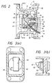
- FIG. 2 is an enlarged sectional view of a tying mechanism portion shown in FIG. 1;
- FIG. 3(a) is a sectional view taken on line A-A of FIG. 2, and FIG. 3(b) is a view taken on line B-B;
- FIGS. 4(a) to 4(c) illustrate the steps of tying operation;
- FIGS. 5(a) to 5(c) illustrate the steps of tying operation following FIG. 4;
- FIGS. 6(a) to 6(c) illustrate the steps of tying operation following FIG. 5;
- FIGS. 7(a) to 7(c) illustrate the steps of tying operation following FIG. 6;
- FIG. 8(a) is a perspective view showing the mode of tying reinforcements by the tying apparatus according to the present invention; FIG. 8(b) is a perspective view showing another mode of tying reinforcements by the tying apparatus according to the present invention;
- FIG. 9(a) is a plan view of the tying apparatus according to another embodiment of the present invention; FIG. 9(B) is a side view thereof;
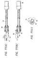
- FIGS. 10(a) to (c) show another embodiment of the tying mechanism of the tying apparatus according to the present invention, FIG. 10(a) being a partly sectional plan view, FIG. 10(b) being a partly sectional front view, and FIG. 10(c) being a left side view;
- FIGS. 11(a) to (c) show the halfway of tying operation of the tying mechanism shown in FIG. 10, FIG. 11(a) being a partly sectional plan view, FIG. 11(b) being a partly sectional front view, and FIG. 11(c) being a left side view;
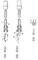
- FIGS. 12(a) to (c) show the state where the tying operation of the tying mechanism shown in FIG. 10 is further progressed, FIG. 12(a) being a partly sectional plan view, FIG. 12(b) being a partly sectional front view, and FIG. 12(c) being a left side view;
- FIGS. 13(a) to (c) show the state where the twisting of the tying mechanism shown in FIG. 10 is completed, FIG. 13(a) being a partly sectional plan view, FIG. 13(b) being a partly sectional front view, and FIG. 13(c) being a left side view;
- FIG. 14(a) is a side schematic view in a state where a cover of the tying apparatus according to another embodiment of the present invention is removed, and FIG. 14(b) is view taken in a direction of C;
- FIG. 15(a) is a side schematic view in a state where a cover of the tying apparatus according to another embodiment of the present invention is removed, and FIG. 15(b) is view taken in a direction of C;
- FIG. 16 is a side schematic view in a state where a cover of the tying apparatus according to still another embodiment of the present invention is removed;
- FIG. 17 is a schematic side view showing another embodiment of tying material feed means in the tying apparatus according to the present invention; and
- FIGS. 18(a) and (b) show a state where an operator wears the tying apparatus according to the embodiment of the present invention using a wearing and holding instrument, FIGS. 18(a) and (b) show the state where the tying is being carried out and the state where the tying is being stopped, respectively.
- The embodiments of the tying apparatus according to the present invention will be described in detail hereinafter with reference to the drawings.
- A
tying apparatus 1 according to the present embodiment comprises a tying materialbobbin holding portion 2, adriving control portion 3, atying mechanism portion 4, and an encompassing and guidingportion 5. These portions can be detachably assembled simply. The detailed construction of these portions will be described below. - In the present embodiment, the tying material
bobbin holding portion 2 combines a rear handle 6 and a battery casing 7 so as to rotatably hold a tyingmaterial bobbin 8. The tying apparatus according to the present embodiment is provided with two handles, i.e., the rear handle 6 and afront handle 24 described later. A rear trigger switch 9 and afront trigger switch 25 are provided at a base portion of the rear handle and at a base portion of thefront handle 24, respectively, so that the tying operation can be done by any of the handles. By the provision of two handles, for example, thefront handle 24 and the rear handle 6 can be held by one hand and by the other hand, respectively, whereby the tying operation can be done comfortably just like the rifle shooting style. Further, the tying operation can be also done in the state where arear end porion 10 of the tying material bobbin holding portion is suspended on a shoulder and only the front handle is held, and the tying operation can be done very comfortably. Therear end portion 10 is slightly projected rearward from the base portion of the rear handle so that the rear end portion of the tying material bobbin holding portion is easily suspended. - The driving
control portion 3 has a tyingmaterial feed motor 15, amain motor 16 and acontrol circuit portion 17 provided with a microcomputer chip mounted within amotor casing 18, which can be integrally mounted and removed from the tying materialbobbin holding portion 2 by means ofconnection bolts 14. The tyingmaterial feed motor 15 and themain motor 16 are integrally provided withreduction gears reduction gear 19 is provided at the output shaft end with a tyingmaterial feed roller 21 as tying material feed means, and anoutput shaft 22 of thereduction gear 20 projects forwardly of themotor casing 18 so that a spindle supported by bearings on the bearing casing of a tying mechanism portion described later can be mounted. - The tying
material feed roller 21 holds a tying material between the former and the other driven roller not shown so as to feed the tying material. The tying material is guided to a tyingmaterial guide pipe 23 provided so as to extend through the motor casing and reach the bearing case of the tying mechanism portion and is fed to thetying mechanism portion 4. - In the present embodiment, since the driving control portion which is subjected to most severe consumption can be integrally mounted and removed, for example, when the motor is broken or reaches a predetermined service life, only the driving control portion can be replaced with a new one simply for use. Further, recently, a small motor which has a long life capable of withstanding about 2,000,000 times of tying has appeared. In the case where such a motor is employed, since the reduction gear, the tying material feed roller and the like first reach their life as compared with the motor, if the tying feed roller or the like which has reached its life is replaced, it can be used again as the driving control portion, which is economical. Furthermore, since the driving control portion can be also integrally replaced, when the motor is replaced, a program of a microcomputer can be changed according to the connection to a control circuit panel and the performance of the motors, and thus, the motor can be replaced very quickly and positively.
- The
type mechanism portion 4 constitutes the most characteristic portion of the present invention, the embodiment of which is clearly shown in an enlarged scale in FIGS. 2 and 3. The tyingmechanism portion 4 is held by aspindle casing 31 detachably mounted by means of aconnection bolt 30 on the front surface of themotor casing 18 of the drivingcontrol portion 3, and comprises, as main members, a bearingcasing 32 secured to the spindle casing, aspindle 33, and an oscillatingmember 43. At a lower portion of the bearingcase 32, a tyingmaterial guide hole 38 in which an end of the tyingguide pipe 23 is fitted is obliquely formed from the lower end toward substantially the axial direction of the spindle. - The
spindle 33 has itsshaft portion 35 rotatably supported by bearings in the bearingcasing 22 throughbearings 36, and asleeve coupling hole 37 in which theoutput shaft 22 of themain motor 16 is fitted is formed in the center portion of the shaft portion. Aflange 39 is formed forwardly, and the aforesaid flange is formed with a tying material extending-through hole 40 which communicates with the tyingmaterial guide hole 38 formed in the bearingcasing 32 so as to guide a tying material w being fed by the tyingmaterial feed motor 15 obliquely upwardly crossing the spindle axis from the lower portion. Further, aninclined guide surface 41 is projected substantially in a central portion of a flange surface in order to guide the tying material having extended through the tying material extending-through hole 40 crossing the spindle axis - Further, the
flange 39 is provided through ashaft 42 with an oscillating member in an oscillating manner. An extreme end portion on the rear surface side of the oscillating member has a folded backmember 44 folded back rearward having enough clearance for a tying material to be fitted to form a groove-like engagingportion 45 on which an extreme end of a tying material having been guided by theinclined guide surface 41 impinges and comes into engagement therewith. Further, ahook 46 constituting twisting means in the folded backmember 44 is provided so that a release portion at the extreme end thereof is vertical with respect to a paper surface in FIG. 2. - On the front surface side (left side in FIG. 2) of the oscillating
member 43 is formed aninclined guide surface 47 for automatically guiding a bent extreme end portion of a tying material guided around an article not to be tied through an encompassing guide described later so as to cause the former to engage thehook 46. Theinclined guide surface 47 is formed to have enough length to cross the extreme end portion of the spindle. - The oscillating
member 43 is normally biased by aspring 44 fitted in theshaft 42 so as to be maintained at a substantially vertical position as shown in FIG. 2. Thespring 44 is formed by two springs, i.e., a weak spring which is pressed by a tying material so that the oscillating member is urged by a weak spring pressure till the oscillation in a predetermined range, and a strong spring which exerts with respect to the oscillation in excess of a predetermined range. - The encompassing and guiding
portion 5 comprises a pair of encompassingguides mechanism portion 4 by means of hinge pins 541, 542 and is normally in an open state biased by a spring as shown by the broken line in FIG. 1. The tyingapparatus 1 is pressed against articles to be tied through an opening whereby articles to be tied engaging members 561, 562 formed on the encompassing guides 551, 552 is pressed by the articles to be tied so that the encompassing guides are closed. - Both encompassing guides are in the form of a continuously substantially semi-oval in their closed state so that articles to be tied a can be positioned inwardly of the encompassing guides. The encompassing guide has a substantially U-shape or V-shape in section whose inside is opened, so that a tying material externally of a tying material to be fed while being folded into a substantially U-shape is moved along the guide surface at the bottom thereof, whereas an internal tying material is stretched internally of the opening, at least a part of which comes in direct contact with the articles to be tied a and is guided thereby. While in the present embodiment, both the encompassing guides are opened and closed, one encompassing guide can be fixed. Alternatively, the encompassing guides may be automatically opened and closed by suitable actuators.
- The tying apparatus according to the present embodiment is constructed as described above. The tying apparatus is automatically actuated in accordance with a preset program by pressing the
trigger switch 9 or 25. While in the present embodiment, a battery as a driving power source is encased in a battery casing for convenience of carrying, it is to be noted of course that an external power source may be employed so as to supply an external power. - The method for tying articles to be tied by the tying apparatus according to the present embodiment constructed as described above will be explained with reference to FIGS. 1 to 8.
- In the state where the encompassing
guide 55 is opened as shown in the imaginary line in FIG. 1, when the article to be tied engaging member 56 is pressed against the outer peripheral portion of the articles a to be tied , encompassingguide 55 rotates so that the articles to be tied assumes a position of the inner peripheral portion of the encompassing guide as indicated by the solid line in FIG. 1. In this state, thetrigger switch 9 or 25 is depressed, whereby the tyingmaterial feed motor 15 is driven and the tyingmaterial feed roller 21 rotates to start the feeding of the tying material. In this state, thespindle 33 stops with the tying material extending-through hole 40 located so as to be positioned on the extension of the tyingmaterial guide hole 38 formed in the bearing casing. - The tying material w delivered from the winding
bobbin 8 is guided by the tyingmaterial guide pipe 23 and is fitted in the tying material guide hole 38 (FIGS. 1 and 2). The tying material is further guided to theinclined guide surface 41 in a direction crossing the spindle axis extending through the tying material extending-through hole 40, and the substantially extreme end thereof impinges upon the front surface wall of the oscillatingmember 43 and slips along the surface thereof into engagement with the engagingportion 45. The oscillating member is pressed by the feeding force thereof and rotate counterclockwise in the figure (FIG. 4(a)). - When the tying material is further fed, and the end of the oscillating
member 43 impinges upon the spindle casing or suitable stopper member to impede its rotation, the tying material w to be delivered is gradually folded, in its extreme end portion, into a substantially U-shape as shown in FIG. 4(b) by the feeding force thereof to form a start point of forming two lines. - When the start point of forming two lines is once formed, the feeding resistance of the tying material becomes weakened, and the oscillating member is somewhat stood up from the FIG. 4(b) state to the FIG. 4(c) state due to the balance of the strong spring with the spring force. Then the engaging portion assumes a position somewhat upward from the spindle axis. In this state, the tying material w is further delivered whereby the extreme end thereof is folded into a substantially U-shape to form a loop and reaches the encompassing
guide 55. In respect of the tying material w, at least a part of the external tying material b is restrained by the encompassingguide 55 through the substantially U-shaped folded extreme end portion c and moves along the guide surface at the bottom thereof whereas the internal tying material d is stretched internally of the opening of the encompassing guide, at least a part of which comes into direct contact with the tying material w and moves on while being guided thereby (FIGS. 4(c) to FIG. 5(c)). - When the folded extreme end portion c is disengaged from the encompassing guide, it impinges upon the inclined guide surface of the oscillating
member 43 positioned in its moving direction and runs on the inclined surface (FIG. 5(b)). The tying material is further fed whereby it is guided by the folded extremeend guide surface 47 so as to be urged sideways and finally runs on the hook (FIG. 5 (c)). However, when the tying material gets over the hook, a support for pressing sideways is lost so that the extreme end portion naturally moves to a central portion, and the folded extreme end portion automatically assumes a state capable of being stopped at the hook (FIG. 6(a)). When assuming this state, an extreme end of a loop is detected by a sensor not shown and the feeding of the tying material is stopped. - Next, the tying material feeding motor is reversely rotated to pull the tying material in a reverse direction whereby the loop is stopped at the hook, and the tying material is completely disengaged from the guide surface of the encompassing guide to assume a tense state (FIG. 6(b)). In the present embodiment, since the tying material is fed from the lower portion so as to cross the spindle axis, in the state where the tying material is in a tense state, the proximal end portion of the tying material is also in a state position in the range of rotation of the hook. Accordingly, according to the present embodiment, there requires no biasing mechanism for bringing the rear end portion of the tying material into engagement with the hook when twisting starts, and such an engagement can be positively made by a simple mechanism. by reversely feeding the tying material, the stretched two lines become closed so that the two lines are not stretched when tying, and the tying can be done successfully.
- The main motor is rotated counterclockwise from the aforesaid state whereby the
spindle 33 rotates. At that time, since the tying material passes through the tying material extending-through hole 40 passing through the tying material guide hole of the fixedbearing casing 32, a relative positional deviation occurs between the tying material guide hole and the tying material extending-hole due to the rotation of the spindle to exert a shearing force on the tying material, and peripheral edges of both the holes constitute a cutting edge to cut the tying material easily (FIG. 6 (c)). In the present embodiment, for facilitating the cutting, the tying material extending-through hole is formed into a spiral slot having an inclined surface with respect to the axis. Accordingly, the tying material can be cut by a weak force. - When the
spindle 33 rotates, the engagingportion 45 as tying material extreme end holding means provided integral with the oscillatingmember 43 mounted on the spindle and thehook 46 also rotate, and in that state, the twisting progresses. At this time, since the hook is pulled toward the articles to be tied as the twisting progresses and the oscillating member is fallen, the twisting can be made in the state where the twisting center coincided with the spindle axis, and the twisting can progress till a clearance with respect to the articles to be tied a disappears. Accordingly, the articles to be tied can be firmly tied to overcome the disadvantages of prior art. - Further, since the hook and the engaging portion are very close to each other in position, the hook is present on the side of an escape groove of the engaging portion, and they are rotated integrally, the end of the tying material engaged with the engaging portion gradually moves toward the escape groove as the twisting progresses and is automatically disengaged from the engaging portion. Therefore, no inferior disengagement occurs even if a disengaging mechanism is not provided in particular (FIG. 7). By applying a predetermined torque to the spindle, termination of tying is automatically detected. By stopping the twisting and reversely rotating the spindle clockwise, the folded portion of the tying material is simply disengaged and the tying terminates. In this state, when the tying apparatus is pulled this side, the encompassing
guide 55 is opened to remove it from the peripheral portion of the articles a to be tied. The operation can be quickly shifted to next mode of operation. -
Reinforcements loop portion 72 are short from a twisted end, the tying can be carried out by an extremely short tying material as compared with that of the conventional tying apparatus. This is very effective for saving the tying materials. Moreover, fastening can be also done. - While one embodiment of the tying apparatus and the tying method according to the present invention has been explained, it is to be noted that the present invention is not limited to the aforementioned embodiment but various changes in design can be made.
- For example, in the above-described embodiment, the hook is secured to the oscillating member. However, when the hook is provided on the oscillating member so as to be oscillated greatly, for example, as twice as the amount of oscillation of the oscillating member by a suitable transmission mechanism such as a gear, when the tying material is encompassed and guided around the articles to be tied, the hook can be positively moved to a position in engagement with the folded extreme end portion to provide more positive engagement. As such, the hook is not necessarily secured to the oscillating member but may be designed to be moved freely.
- Further, while in the above-described embodiment, the termination of tying is automatically detected by applying a predetermined torque to the spindle, and the spindle is automatically reversely rotated and is disengaged from the folded portion of the tying material, it is to be noted that the present invention is not limited thereto but the hook is rotated in the same direction as it is and a torque in excess of a predetermined value is applied to the spindle whereby the tying material can be torn off from the neighborhood of the folded portion and the hook can be naturally removed from the tying wire. The tying mode in case of being tied in such a manner as described is shown in FIG. 8(b).
- In this case, there assumes a state where the
loop portion 72 and the cutting ends 70, 71 are cut away from the twisted end of the tying material w by which thereinforcements loop portion 72 and the cutting ends 70, 71 are cut in a state of 3-piece or in a state of one piece. - While in the embodiment shown in FIG. 1, the winding bobbin is supported on the tying material bobbin holding portion, it is to be noted that the winding bobbin, the driving control portion and the like may be placed at a position separately from the tying apparatus body, or they can be carried on the waist by a band or the like to draw therefrom. Further, while in the above-described embodiment, one tying material is drawn out of one winding bobbin, which is folded into two wires, and the tying is carried out by one winding of the two wires, it is to be noted that two winding bobbins may be mounted to simultaneously draw two tying materials together, which are folded to provide one winding comprising four wires, and further, one winding tying with the number of tying materials more than the above can be made. The number of tying materials is increased whereby even if a diameter of each tying material is made small, the strength can be enhanced, and a flexibility can be increased to reduce the curvature of the encompassing guide, thus further miniaturizing the tying apparatus.
- While in the above-described embodiment, the front handle is provided at the lower side of the driving control portion, the front handle is not necessarily limited to the aforesaid position but as in a
tying apparatus 64 shown in FIGS. 9(a) and (b), afront handle 66 can be provided sideways of amotor casing 65 of the driving control portion, and a suitable position can be selected. Since other structures of the tying apparatus shown in FIG. 9 are similar to those of the previous embodiments, detailed description is omitted. - While in the above-described embodiment, the battery casing 7 is mounted on the apparatus body, it is to be noted that it is convenient if a design is made so as to suitably select, according to the situation of an operator, a case where a battery casing is detachably mounted on the apparatus body and is mounted on the body, or a case where for example, a battery casing is supported on the waist of an operator and is connected to the body through a cable from the waist. In this case, preferably, the battery case and the apparatus body are always linked through the cable in order to prevent inferior contact.
- Further, in the case where articles are tied, for example, by hard tying materials having a high strength, the encompassing guide receives a high resistance from the tying material to be opened in order to guide the tying material around the articles to be tied. On the other hand, in a case of a tying machine applied to an application which uses a hard tying material having particularly high strength in order to positively tie the articles to be tied without opening the encompassing guide, it is preferable to provide a locking mechanism which is automatically locked to impede the opening of the encompassing guide in the case where the encompassing guide encases therein articles to be tied.
- Further, in the case where a clearance through which the encompassing guides move into a position to be tied such as reinforcements placed on the ground or floor surface is small, it is preferred that rollers are provided outwardly of one of the encompassing guides in order to allow the encompassing guides to move in easily.
- Moreover, while in the above-described embodiment, the tying material is fed from the lower porion so as to cross the spindle axis, it is to be noted that such is not always necessary but for example, even if the tying material is fed by the guiding mechanism in a direction parallel with the spindle axis, similar effects can be obtained. Furthermore, while in the above-described embodiment, the tying material bobbin holding portion, the driving control portion, the tying mechanism and the encompassing and guiding portion are connectable each other, it is to be noted that an embodiment is not always limited to the above-described embodiment but for example, a body frame is formed, and a part or whole of the aforementioned portions can be detachably mounted on the body frame in a cassette system, and in addition, the whole body can be integrally formed.
- Further, the tying apparatus according to the present invention is not always limited to a portable type but for example, a power source and a control portion can be provided outside, or a tying material bobbin can be largely provided outside and mounted on an operating robot. The tying apparatus of the present invention exhibits a great effect in tying and securing reinforcements in the preparation operation as shown in FIG. 8. However, articles to be tied are not limited to reinforcement but are also useful for, for example, a tying of articles to be tied such as bar-like articles and pipes, and a tying of a single article to be tied such as a tying of an opening of a bag, and a tying and securing of heat insulating sheets wound about pipes or ducts. There further includes various tyings for raw materials in the production of food such as ham, and a tying of the meshes in repair of fishing nets or the like. Further, if the tying apparatus body is super-miniaturized and tying materials are selected, it can be also applied to an apparatus for performing medical tying such as sewing and connection after operation of human being and animal. The present tying apparatus can be applied to tying of various kinds of articles if the latter can be tied.
- FIGS. 10 to 17 show another embodiment of the tying apparatus according to the present invention. Out of these drawings, FIGS. 10 to 13 show another embodiment of the tying mechanism portion of the tying apparatus according to the present invention. The tying mechanism portion in the present embodiment is similar to that of the previous embodiment in fundamental tying method but unlike the previous embodiment, the present embodiment is characterized in that a spindle body is displaced along the axis as the twisting progresses. In the figures,
reference numeral 80 designates a main motor, and 81 designates a sleeve coupling. Aspindle 83 is connected to anoutput shaft 82 of the main motor axially displaceably through the sleeve coupling. - An
extreme end member 85 is pivotally mounted by apin 86 in an oscillating manner on the extreme end portion of thespindle 83, theextreme end member 85 being supported on asleeve 87 rotatably supported by bearings on a bearingcasing 84. Theextreme end member 85 can be slidably moved axially with respect to thesleeve 87 but can be rotated integral with thesleeve 87. Thesleeve 87, theextreme end member 85 and thespindle 83 constitute a spindle body. In the vicinity of the base of theextreme end member 85 is formed aninclined surface 88 for reducing a rotational radius of a hook which performs a function of reducing a rotational radius of a hook as the twisting progresses. Thespindle 83 is biased leftward in the figure by means of aspring 91 provided between a fixedmember 89 secured to the body casing and aflange 90 secured to the spindle so as to return the hook to its initial position. - Further, in the extreme end portion of the
extreme end member 85 is formed aguide surface 97 for guiding a tying material to an engaging portion while being crossed with an axis of a spindle and is provided with a bentextreme end piece 92. An oscillatingmember 93 is pivotally mounted by apin 94 in an oscillating manner on the bentextreme end piece 92. The oscillatingmember 93 is provided with an engaging portion as tying material holding means with which an extreme end portion of a tying material engages to bend it into a U-shape, and ahook 95. - The tying mechanism portion in the present embodiment is constructed as described above, and the operation thereof will be described with reference to FIGS. 10 to 13. It is to be noted that since the fundamental twisting operation is similar to that of the previous embodiment, only the characteristic operation of the present embodiment will be described.
- FIG. 10 shows the state where the
hook 95 is at an original position before the tying operation starts. When the tying operation starts, the tying material delivered passes through a tyingmaterial guide hole 96 formed in the bearingcasing 84, is guided to aguide surface 97, and impinges upon the guide surface of the oscillatingmember 93. The extreme end portion thereof comes in engagement with the engaging portion whereby the oscillatingmember 93 is oscillated forward (clockwise in FIG. 10(b)) about thepin 94 by the feeding force of the tying material, and is maintained at a position where the hook can be engaged with the bent extreme end portion of the tying material being guided via the encompassing guide, as shown in FIG. 11. - When the bent extreme end portion of the tying material arrives at the position in engagement with the hook via the encompassing guide, the hook rotates into engagement with the bent extreme end portion of the tying material w (FIG. 11(a)) and the tying material is reversely fed whereby the hook is subjected to tension in a direction of arrow in FIG. 12 to compress the
spring 91 so that the spindle moves in a direction of arrow (FIG. 12), in which state the twisting starts. As the twisting progresses, the hook is subjected to a force to be gradually pulled in the direction of articles to be tied, and therefore thespring 91 is further compressed and thespindle 83 moves toward the articles to be tied. Then, when the inclined surface of the extreme end member arrives at the end of the sleeve, the extreme end member can be oscillated about thepin 86 by a clearance between the inclined surface and an extreme end edge of the sleeve. As the inclined surface deepens, the extreme end member is inclined to gradually reduce the twisting radius so that the engaging point between the articles to be tied and the hook assumes a state to be positioned on the twisting center line, in which state the twisting progresses to the end (FIG. 13). - As described above, as the twisting progresses, the hook moves toward the articles to be tied, and the twisting can be made in the state where the rotational radius of the twisting is gradually reduced so that the engaging point assumes a position on the twisting center line. Therefore, the twisting can be made without occurrence of excessive conical motion in the twisting proximal end during the progress of twisting. It is possible to progress the twisting successfully till a clearance with respect to the articles to be tied disappears without fatigue of the tying material.
- FIG. 14 shows another embodiment of the tying apparatus according to the present invention. In the present embodiment, a winding bobbin, a tying material feed motor and a control portion are separated from the tying apparatus body to provide a separate casing. The separate casing is carried on the waist or the like by a band, as shown in FIG. 18, from which a tying material is drawn whereby the tying apparatus body held by hands can be light-weighted, and the tying operation can be carried out more comfortably and efficiently.
- In FIG. 14,
reference numeral 100 designates a tying apparatus body which is held by hands to carry out a tying operation. A tying mechanism portion is substantially similar to that of the previous embodiment, but a tyingmaterial feed motor 101 is separated and is encased in aseparate casing body 102 which can be carried on the waist while being mounted on a band or the like not shown. The tyingapparatus body 100 comprises amain motor 115, a tyingmechanism portion 116, an encompassing and guidingportion 117, and ahandle 119 having atrigger switch 118. Further, theseparate casing body 102 comprises a tying materialbobbin holding portion 103 for rotatably holding the tyingmaterial bobbin 8, abattery casing 104 for encasing therein a battery as a power source portion, and acontrol circuit portion 105. - However, tying material feeding means 106 is provided on the
tying apparatus body 100 to transmit a torque of the tyingmaterial feed motor 101 to the tying material feeding means 106 through aflexible shaft 107. In the present embodiment, the tying material feeding means 106 has a mechanism in which as shown in FIG. 14(b), a tying material is held between adrive gear 108 and a drivengear 109 to deliver the tying material by means of a frictional force of the drive gear, being transmitted to the drive gear through abevel gear 110 provided on the end of theflexible shaft 107. Further, the tying material feeding means 106 can be detachably mounted together with its casing on the apparatus body as shown so that when a roller is damaged, only that part can be replaced simply. This is also true for the case of an embodiment shown in FIG. 15. In the case of the embodiment of FIG. 15, tying material feeding means 125 is detachably mounted on aseparate casing 126. - The tying material w passes, between the
separate casing 102 and the tyingmachine body 100, through aflexible guide tube 111. The guide tube passes through a large diameterflexible pipe 113 collectively together with theflexible shaft 107 and a power source/signal cable 112, and therefore, successful feeding can be obtained without occurrence that it is bent small halfway of feeding or is entangled with the flexible shaft or the power source/signal cable. Moreover, in the present embodiment, even if the tyingmaterial feed motor 101 is encased in theseparate casing body 102, the tying material feeding means 106 is present in the tying apparatus body. Therefore, the tying material is pulled out on the side of the tying apparatus body, and is not bent halfway and can be fed satisfactorily with less resistance. - It is to be noted that the tying material feeding means is not limited to the configuration comprising a pair of gears, but suitable means such as a belt system shown in FIG. 15(b) and a system having plural pairs of feed gears shown in FIG. 17 described later can be employed. Further, the
separate casing body 102 is constructed such that a tying bobbin holding portion, a tying material feed motor, a control circuit portion and a battery casing are individually separatably assembled. For example, when the tying material feed motor or the tying material feeding means is consumed, only the consumed one can be replaced for use. Further, while in the present embodiment, a battery is used as a power source, it is to be noted of course that a commercial power can be also used, in which case a commercial power adapter can be connected to the power source portion. - In the tying apparatus according to the present embodiment, the tying material feed motor, the tying material bobbin, the battery and the control circuit portion are encased in the separate casing body and separated from the tying apparatus body. Therefore, the tying apparatus can be constructed to be very small and light weight. Since the separate casing is attached to the waist or the like for operation, the tying apparatus body held by hands is very light weight, and even women or children can perform the tying operation comfortably. In this case, it is of course that the tying mechanism can be applied to not only the tying machine in the above-described embodiment but also a tying machine having a tying mechanism of other types.
- Further, the tying
mechanism portion 116, the encompassing and guidingportion 117 and the like in the present embodiment are fundamentally similar to those of the previous embodiment, but in the present embodiment, aspindle 120 is provided with anorigin producing cam 121 rotated integral with the spindle, and a detected portion provided at a specific position of an outer peripheral surface of theorigin producing cam 121 is detected by anorigin sensor 122 provided at a fixed position of the tying apparatus body whereby an origin angle position of ahook 123 can be detected. Thereby, when the tying starts, thehook 123 is located to a position where thehook 123 can be always engaged with the bent end of the tying material so that the hook can be positively engaged with the bent end of the tying material to start the twisting. - FIG. 15 shows a modified example of the embodiment shown in FIG. 14, which example is different from the previous embodiment in that tying material feeding means 125 is mounted on a
separate casing 126. The tying material feeding means 125 in the present embodiment is composed of a pair of feed belts comprising adrive feed belt 127 and a drivenfeed belt 128 in order to increase a feeding force. Since other structures are similar to those of the embodiment shown in FIG. 14, the same reference numerals are applied to the same members, and a detailed description is omitted. - FIG. 16 shows a further modified example of the embodiment shown in FIG. 14, in which example, a
main motor 130 is also separated from atying apparatus body 131 and encased in aseparate casing body 132 so as to rotate and drive the spindle of the apparatus body through aflexible shaft 155. Accordingly, in the case of the present embodiment, the tyingapparatus body 131 is further light-weighted. Since other structures are similar to those of the embodiment shown in FIG. 14, the same reference numerals are applied to the same members, and a detailed description is omitted. - FIG. 17 shows another embodiment of the tying material feeding means. Tying material feeding means 135 in the present embodiment is so designed as to feed a tying material by two pairs of gears in order to further increase a feeding force as compared with the case of the pair of gears shown in FIG. 14(b). In FIG. 17,
reference numeral 136 designates a gear rotated and driven by a tying material feed motor; 137, 137', drive gears meshed with the first mentioned gear and driven; and 138, 138', driven gears. - As the tying material feeding means, for example, a tying material feeding roller formed with a spiral groove is employed to feed a tying material in a state where the tying material is wound about the roller once or twice whereby even a tying wire, which is coated, for example, with a synthetic resin, and is thus slippery, can be positively fed.
- FIG. 18 shows an embodiment of a tying apparatus mounting holder, in which in the case where the tying operation is carried out by the tying apparatus having the tying apparatus body separated from the separate casing body as in the above-described embodiment, the tying operation can be carried out comfortably.
- The tying
apparatus mounting holder 140 in the present embodiment comprises abelt 141 for detachably holding a separate casing body 150, a tying apparatusbody encasing pocket 142 for encasing therein atying apparatus body 151 held by said belt, and a 'tasuki'body 144 having engagingmeans 143 for engageably holding aflexible tube 153 which extends from thebelt 141 to a shoulder in the form of the 'tasuki' to collectively guide to a shoulder position so as not to get in the way of a tying material, a flexible shaft, a signal wire, etc. extending from theseparate casing body 152 to thetying apparatus body 151. - Accordingly, during the tying operation, as shown in FIG. 18(a), the
separate casing body 152 is attached to the belt and held on the waist, theflexible tube 153 is placed in engagement with the engaging means 143 of the 'tasuki' 144 so that theflexible tube 153 may not slip down from the shoulder, and only the tying apparatus body can be held by one hand to perform the tying operation. The tying apparatus is very light weight and comfortable as compared with prior art, and the operation can be done successfully without getting in the way of the tying wire, the flexible cable, the signal wire, etc. and the workability can be materially improved. Further, when the operator stops the operation and moves to somewhere, the tyingapparatus body 151 can be encased in the tying apparatusbody encasing pocket 142 as shown in FIG. 18(b). Therefore, the tying apparatus body is not to get in the way and both hands can be used. Thus, the operator can move safely to even a dangerous work site, and in that state, the operator can perform other operations and can carry articles. - As described above, according to the present invention, a continuous linear tying material can be delivered and automatically folded into two wires for tying articles. Therefore, as compared with prior art in which a single wire is wound to tie articles, the strength of the tying material is enhanced and the articles can be firmly tied with an extremely powerful tying force.
- Particularly, in the present invention, the tying material holding means for holding the end of the tying material is rotated and oscillated integral with the spindle whereby the tying material holding means is displaced in an axial direction of the spindle. Therefore, the twisting can progress from the neighborhood of the engaging end of the tying material, the tying material can be tied with a short length as compared with prior art, and the consumption of the tying materials can be reduced. In addition, because of the twisting in the spindle axis, the rotational load of the main motor for twisting will suffice to be less.
- Further, since the disengaging action from the engagement holding means exerts on the engaging end of the tying material during the twisting, the disengagement of the engaging end from the engagement holding means can be positively carried out. Further, the hook is mounted on the oscillating member, and the inclined guide surface is formed on the oscillating member whereby the extreme end of the loop can be positively positioned at the hook engaging position, and the reliable operation is obtained.
- Furthermore, the tying material holding means and the hook are displaced toward the articles to be tied during the process of step, and the tying material holding portion and the hook are rotated integrally at a position very close to each other. Therefore, the twisting can progress till reaching the twist end, and the articles can be firmly tied. Further, the center of the twist can be twisted on the spindle axis. It is possible to prevent stress from repeatedly exerting on the twisted base portion during the twisting and prevent the tying material from being cut or deteriorated during the twisting.
- Further, in the case where the driving control portion of the motor or the like is damaged, it can be replaced together with the motor casing with a new one at the on-site. Therefore, the operation can continue. The replaced driving control portion of the motor can be recovered and only a damaged portion can be replaced at the factory for re-use, which is economical. Furthermore, the control circuit panel of the driving control portion is integrally replaced whereby even if the kind of machine is changed, the connection to the control circuit panel and the program of a microcomputer in accordance with the performance of the motor can be changed. Therefore, it is possible to replace the panel very simply and positively.
- By separating the tying apparatus into the tying apparatus body and the separate casing body, the heavy tying material bobbin and the tying material feed motor can be held on the waist, and the tying apparatus body can be extremely miniaturized and light weighted. The tying operation can be carried out very comfortably as compared with prior art. At this time, even if the tying material feed motor is encased in the separate casing body, when the tying material feeding means is provided on the tying apparatus body, the tying material is pulled out on the side of the tying apparatus body, and the tying material can be fed successfully with less resistance without being folded halfway.
- As described above, the tying method and the tying apparatus according to the present invention exhibits a great effect in tying reinforcements in the preparation operation. However, the present method and the apparatus are useful for a tying of articles to be tied such as not only reinforcement but rods, pipes, etc., a tying of an opening of a bag, a tying of a single article to be tied such as winding of heat insulating sheets around pipes and ducts and securing the same. Further, since the apparatus is simple in construction, it is also possible to obtain a super-small and light weight tying apparatus. If special wires are used as tying materials, they can be applied to a tying apparatus for various articles such as medical sewing and connection or sewing and repair of fishing nets or the like. Further, the present tying apparatus can be utilized as not only a portable use in which an operator holds the apparatus by his hands for operation but also a tying operation hand attached to a robot arm.
Claims (20)
- A method of tying articles comprising: a tying material bending step of holding a substantially extreme end portion of a continuous linear typing material being delivered by tying material holding means to apply a resistance to form a start point at which the tying material is bent into a substantially U-shape; an encompassing and guiding step of guiding said tying material around an article to be tied while bending the former into a substantially U-shape; a tying material cutting step of cutting a rear end portion of said tying material from a continuous wire at a suitable time; and a twisting step of twisting a bent extreme end portion and a rear end portion on the other side of said tying material together to band the article to be tied, said bent extreme end portion and said rear end portion on the other side of said tying material being twisted together while said tying material holding means and said twisting means are rotated integrally.
- The method of tying articles according to claim 1, wherein said tying material is fed to a holding portion of said tying material holding means from a direction crossing an axis of a spindle to have a substantially extreme end portion engaged with said holding portion.
- The method of tying articles according to claim 1 or 2, wherein a bent extreme end portion and a rear end portion of the tying material are twisted together each other while said tying material holding means and said twisting means are integrally displaced in an axial direction of a spindle.
- The method of tying articles according to claim 1 or 2, wherein a bent extreme end portion and a rear end portion of the tying material are twisted together each other while said tying material holding means and said twisting means are integrally displaced towards articles to be tied.
- The method of tying articles according to claim 1 or 2, wherein in said twisting step, a predetermined or more torque is applied to the spindle even after completion of twisting whereby the neighbourhood of a loop portion of the tying material engaged with a hook of the twisting means is torn off and a tying end of the tying material is disengaged from the engagement with the hook.
- A method of tying articles comprising: a tying material bending step of holding a substantially extreme end portion of a continuous linear typing material being delivered by tying material holding means to apply a resistance to form a start point at which the tying material is bent into a substantially U-shape; an encompassing and guiding step of guiding said tying material around an article to be tied while bending the former into a substantially U-shape; a tying material cutting step of cutting a rear end portion of said tying material from a continuous wire at a suitable time; and a twisting step of twisting a bent extreme end portion and a rear end portion on the other side of said tying material together to band the article to be tied, said tying material being fed to a holding portion of said tying material holding means from a direction crossing a spindle, substantially an extreme end portion being engaged with said holding portion.
- An apparatus of tying articles comprising tying material delivery means (21, 106, 125, 135) for delivering a continuous linear tying material; tying material holding means for holding an end of the tying material delivered from said tying material delivery means; encompassing and guiding means (5, 117) for guiding, around articles to be tied, a tying material while being bent into a substantially U-shape in a state where a substantially end portion thereof is held by said tying material holding means; cutting means for cutting said tying material into a predetermined length; and twisting means for twisting opposite ends of the tying material together, characterized in that said tying material holding means is provided on a spindle body to be rotated and driven and is rotated integral with said twisting means.
- The tying apparatus according to claim 7, wherein said tying material holding means and said twisting means are provided on said spindle body so that they can be displaced toward the articles to be tied as the twisting progresses.
- The tying apparatus according to claim 7 or 8, wherein said tying material holding means and said twisting means are provided on an oscillating member provided on said spindle body in an oscillating manner.
- The tying apparatus according to claim 9, wherein said tying material holding means comprises an engaging portion (45) in which a tying material is fitted provided at a substantially extreme end portion of said oscillating member, and said tying material twisting means comprises a hook (46, 95, 123) provided adjacent to said engaging portion.
- The tying apparatus according to claim 7 or 10, wherein a fixed member for rotatably holding said spindle body is formed with a tying material hole (38, 96) for guiding said tying material w in a direction crossing the spindle axis, said spindle body being provided with a tying material extending-through hole (40) which is communicated with said tying material guide hole to cause the tying material to extend through in a direction crossing the spindle axis, said tying material being held by said tying material holding means from a direction crossing the spindle axis.
- The tying apparatus according to claim 11, wherein said cutting means is formed by hole edges of said tying material guide hole and said tying material extending-through hole, and the tying material is cut from a continuous line by the relative rotational movement between said tying material guide hole and said tying material extending-through hole.
- The tying apparatus according to claim 9, wherein said spindle body is provided so as to be displaced toward the articles to be tied as the twisting progresses.
- The tying apparatus according to claim 13, wherein said spindle body comprises a spindle (83) rotated and driven by a main motor (80) and a spindle extreme end portion (85) pivotally mounted on the extreme end thereof, and said oscillating member is provided at substantially the extreme end portion of said spindle extreme end member so that as said spindle body is displaced toward the articles to be tied as the twisting progresses, said spindle extreme end member (85) oscillates so as to reduce the rotational radius of said twisting means.
- An apparatus of tying articles comprising: a tying material bobbin holding portion (2), a driving control portion (3), a tying mechanism portion (4), an encompassing and guiding portion (5) and a tying material cutting portion, said driving control portion comprising a tying material feed motor (15), a main motor (16) for rotating and driving a spindle body of said tying mechanism portion, and a control circuit portion (17) for controlling said tying material feed motor (15) and said main motor (16), said driving control portion (3) being characterized by capable of being integrally detached with respect to said tying material bobbing holding portion (2) and said tying mechanism portion (4).
- A tying apparatus comprising a tying material feed motor (101), tying material feed means (106, 125, 135) rotated and driven by said tying material feed motor, a main motor (115, 130), and a tying mechanism portion twisting means rotated and driven by said main motor, characterized in that said apparatus is separated into at least a tying apparatus body (100, 131) having said tying mechanism portion and at least a separate casing body (102, 126, 132) having said tying material feed motor, and a tying material is fed from said separate casing to the tying mechanism portion of said tying apparatus body by the tying material feed motor (101).
- The tying apparatus according to claim 16, wherein the main motor (130) is provided on the separate casing (132), and said tying mechanism portion is rotated and driven through a flexible shaft (155) from said main motor.
- The tying apparatus according to claim 16, wherein the main motor (115) is provided on said tying apparatus body.
- The tying apparatus according to claim 16, wherein said tying material feeding means (106) is detachable from the tying apparatus body (100, 131) or the separate casing (126).
- The tying apparatus according to claim 16, 17, 18 or 19 wherein said tying material feeding means is present in said tying apparatus body, said tying material feeding means being rotated and driven through a flexible shaft from the tying material feed motor (101) which is present in said separate casing body (102, 132), and the tying material is drawn out of the tying material bobbin (8) held on said separate casing body (102, 132) for said tying apparatus body (100, 131).
Applications Claiming Priority (7)
| Application Number | Priority Date | Filing Date | Title |
|---|---|---|---|
| JP5200195 | 1995-02-17 | ||
| JP5200195 | 1995-02-17 | ||
| JP52001/95 | 1995-02-17 | ||
| JP352209/95 | 1995-12-28 | ||
| JP35220995 | 1995-12-28 | ||
| JP35220995 | 1995-12-28 | ||
| PCT/JP1996/000343 WO1996025330A1 (en) | 1995-02-17 | 1996-02-16 | Article binding method and apparatus |
Publications (3)
| Publication Number | Publication Date |
|---|---|
| EP0810153A1 true EP0810153A1 (en) | 1997-12-03 |
| EP0810153A4 EP0810153A4 (en) | 1998-04-29 |
| EP0810153B1 EP0810153B1 (en) | 2001-11-07 |
Family
ID=26392599
Family Applications (1)
| Application Number | Title | Priority Date | Filing Date |
|---|---|---|---|
| EP96902457A Expired - Lifetime EP0810153B1 (en) | 1995-02-17 | 1996-02-16 | Article binding method and apparatus |
Country Status (8)
| Country | Link |
|---|---|
| US (1) | US5944064A (en) |
| EP (1) | EP0810153B1 (en) |
| KR (1) | KR100423385B1 (en) |
| CN (1) | CN1064319C (en) |
| AU (1) | AU4675896A (en) |
| DE (1) | DE69616761T2 (en) |
| TW (1) | TW312672B (en) |
| WO (1) | WO1996025330A1 (en) |
Cited By (5)
| Publication number | Priority date | Publication date | Assignee | Title |
|---|---|---|---|---|
| WO2001094206A1 (en) * | 2000-06-06 | 2001-12-13 | Kim Michael Jensen | A method and an apparatus for twisting and tightening a wire |
| WO2004021769A1 (en) * | 2002-09-05 | 2004-03-18 | Alfons Alber | Device for fastening plant parts |
| EP1484249A1 (en) * | 2002-03-12 | 2004-12-08 | Max Co., Ltd. | Reinforcing bar binding machine |
| US8607696B2 (en) | 2007-11-20 | 2013-12-17 | Jbj Mechatronic Aps | Binding apparatus |
| US9255415B2 (en) | 2009-05-27 | 2016-02-09 | Jbj Mechantronic Aps | Binding apparatus |
Families Citing this family (36)
| Publication number | Priority date | Publication date | Assignee | Title |
|---|---|---|---|---|
| FR2814717B1 (en) * | 2000-10-04 | 2003-02-28 | Papeteries Matussiere Forest | APPARATUS FOR AUTOMATICALLY LAYING TWISTED LINKS |
| AU2002318747B2 (en) * | 2001-07-19 | 2008-02-21 | Max Co., Ltd | Reinforcing steel bar tying machine |
| JP4729822B2 (en) * | 2001-08-08 | 2011-07-20 | マックス株式会社 | Bundling wire feed mechanism for reinforcing bar binding machine |
| CN102720366B (en) * | 2005-10-10 | 2016-04-06 | 建筑设备私人有限公司 | For by binding objects to equipment together |
| US11999516B2 (en) | 2008-04-23 | 2024-06-04 | Signode Industrial Group Llc | Strapping device |
| US10518914B2 (en) | 2008-04-23 | 2019-12-31 | Signode Industrial Group Llc | Strapping device |
| JP5532610B2 (en) * | 2008-05-19 | 2014-06-25 | マックス株式会社 | Wire reel and rebar binding machine |
| CN102101541B (en) * | 2011-03-30 | 2012-08-29 | 广州广电运通金融电子股份有限公司 | Strip medium strapping mechanism and strapping method |
| CN103010507A (en) * | 2011-09-23 | 2013-04-03 | 邓社文 | Knotting machine |
| CA2990150C (en) | 2015-07-22 | 2019-08-20 | Max Co., Ltd. | Binding machine |
| CA2990149C (en) * | 2015-07-22 | 2020-01-28 | Max Co., Ltd. | Binding machine |
| CN105197279B (en) * | 2015-09-07 | 2017-05-17 | 温州智信机电科技有限公司 | Segmented bundling equipment for strip-shaped soft materials |
| JP6887760B2 (en) * | 2016-05-20 | 2021-06-16 | 株式会社マキタ | Reinforcing bar binding machine |
| US10061323B2 (en) | 2016-12-22 | 2018-08-28 | Advanced Construction Robotics, Inc. | Autonomous apparatus and system for repetitive tasks in construction project |
| JP6834485B2 (en) * | 2016-12-29 | 2021-02-24 | マックス株式会社 | Cable ties |
| USD864688S1 (en) | 2017-03-28 | 2019-10-29 | Signode Industrial Group Llc | Strapping device |
| EP3363577A1 (en) * | 2017-02-17 | 2018-08-22 | Sund Birsta AB | Binding machine and method for securing a part of a binding element in a loop around one or more objects |
| JP7081166B2 (en) * | 2017-06-07 | 2022-06-07 | マックス株式会社 | Cable ties |
| US11365552B2 (en) | 2017-06-07 | 2022-06-21 | Max Co., Ltd. | Binding machine |
| SE541178C2 (en) | 2017-09-08 | 2019-04-23 | Skanska Sverige Ab | A tool, a system and a method for manufacturing of a reinforcement bar structure |
| JP6985928B2 (en) * | 2017-12-27 | 2021-12-22 | 株式会社マキタ | Cable ties |
| FR3079106B1 (en) * | 2018-03-20 | 2020-05-29 | Pellenc | APPARATUS FOR LAYING WIRE TIES |
| JP7275486B2 (en) | 2018-07-18 | 2023-05-18 | マックス株式会社 | binding machine |
| JP7354687B2 (en) * | 2018-09-07 | 2023-10-03 | マックス株式会社 | tying machine |
| JP7379941B2 (en) * | 2018-09-07 | 2023-11-15 | マックス株式会社 | tying machine |
| JP7275506B2 (en) | 2018-09-07 | 2023-05-18 | マックス株式会社 | binding machine |
| EP3848293A4 (en) * | 2018-09-07 | 2022-05-25 | Max Co., Ltd. | Binding machine |
| US20210237143A1 (en) * | 2018-09-07 | 2021-08-05 | Max Co., Ltd. | Binding machine |
| US10597264B1 (en) | 2018-12-20 | 2020-03-24 | Advanced Construction Robotics, Inc. | Semi-autonomous system for carrying and placing elongate objects |
| CN109930838B (en) * | 2019-04-23 | 2021-02-26 | 车建民 | Reinforcing steel bar binding machine |
| EP4051853A4 (en) * | 2019-10-28 | 2024-01-17 | Husqvarna Ab | Rebar tying device comprising a wire locking mechanism and a control unit for controlling the wire locking mechanism |
| US11529669B2 (en) | 2019-12-17 | 2022-12-20 | Makita Corporation | Rebar tying tool |
| JP7508800B2 (en) * | 2020-02-10 | 2024-07-02 | マックス株式会社 | Binding machine |
| EP3862511A1 (en) | 2020-02-10 | 2021-08-11 | Max Co., Ltd. | Binding machine |
| IT202000021862A1 (en) * | 2020-09-16 | 2022-03-16 | Schnell Spa | METHOD AND EQUIPMENT FOR BINDING METAL WIRE AND SIMILAR PRODUCTS |
| JP2023127598A (en) * | 2022-03-02 | 2023-09-14 | マックス株式会社 | Binding machine |
Family Cites Families (10)
| Publication number | Priority date | Publication date | Assignee | Title |
|---|---|---|---|---|
| US3880204A (en) * | 1974-02-19 | 1975-04-29 | Forest M Sarff | Wire tying mechanism |
| JPS58177275A (en) * | 1982-04-08 | 1983-10-17 | 鹿島建設株式会社 | Wire type reinforced bundling tool |
| EP0408987B1 (en) * | 1989-07-15 | 1994-12-28 | Kress-elektrik GmbH + Co. Elektromotorenfabrik | Electric tool |
| JPH06115509A (en) * | 1992-02-28 | 1994-04-26 | Bentatsuku:Kk | Method and device for binding article |
| JPH0699926A (en) * | 1992-09-14 | 1994-04-12 | Yoshiaki Tange | Tying machine |
| JPH06167115A (en) * | 1992-11-30 | 1994-06-14 | Takahashi Eng:Kk | Building device of bar member |
| JPH06278049A (en) * | 1993-03-30 | 1994-10-04 | Osaka Rasenkan Kogyo Kk | Binding tool |
| JP3393684B2 (en) * | 1993-08-16 | 2003-04-07 | 株式会社エスディーコーポレーション | Article binding method and binding apparatus |
| JP3077731B2 (en) * | 1993-11-08 | 2000-08-14 | マックス株式会社 | Guide mechanism for the binding wire in the binding machine |
| US5431196A (en) * | 1994-01-03 | 1995-07-11 | Belcan Specialty Equipment Engineering Division Of Belcan Engineering Groups, Inc. | Power rebar tying tool |
-
1996
- 1996-02-16 AU AU46758/96A patent/AU4675896A/en not_active Abandoned
- 1996-02-16 WO PCT/JP1996/000343 patent/WO1996025330A1/en active IP Right Grant
- 1996-02-16 US US08/894,148 patent/US5944064A/en not_active Expired - Fee Related
- 1996-02-16 KR KR1019970705533A patent/KR100423385B1/en not_active IP Right Cessation
- 1996-02-16 EP EP96902457A patent/EP0810153B1/en not_active Expired - Lifetime
- 1996-02-16 DE DE69616761T patent/DE69616761T2/en not_active Expired - Fee Related
- 1996-02-16 CN CN96191972A patent/CN1064319C/en not_active Expired - Fee Related
- 1996-08-15 TW TW085109933A patent/TW312672B/zh active
Non-Patent Citations (2)
| Title |
|---|
| No further relevant documents disclosed * |
| See also references of WO9625330A1 * |
Cited By (8)
| Publication number | Priority date | Publication date | Assignee | Title |
|---|---|---|---|---|
| WO2001094206A1 (en) * | 2000-06-06 | 2001-12-13 | Kim Michael Jensen | A method and an apparatus for twisting and tightening a wire |
| EP1484249A1 (en) * | 2002-03-12 | 2004-12-08 | Max Co., Ltd. | Reinforcing bar binding machine |
| EP1484249A4 (en) * | 2002-03-12 | 2006-07-05 | Max Co Ltd | Reinforcing bar binding machine |
| US7275567B2 (en) | 2002-03-12 | 2007-10-02 | Max Co., Ltd. | Reinforcing bar binding machine |
| AU2003221335B2 (en) * | 2002-03-12 | 2008-07-10 | Max Co., Ltd. | Reinforcing bar binding machine |
| WO2004021769A1 (en) * | 2002-09-05 | 2004-03-18 | Alfons Alber | Device for fastening plant parts |
| US8607696B2 (en) | 2007-11-20 | 2013-12-17 | Jbj Mechatronic Aps | Binding apparatus |
| US9255415B2 (en) | 2009-05-27 | 2016-02-09 | Jbj Mechantronic Aps | Binding apparatus |
Also Published As
| Publication number | Publication date |
|---|---|
| EP0810153A4 (en) | 1998-04-29 |
| KR100423385B1 (en) | 2004-07-19 |
| TW312672B (en) | 1997-08-11 |
| US5944064A (en) | 1999-08-31 |
| EP0810153B1 (en) | 2001-11-07 |
| DE69616761T2 (en) | 2002-08-01 |
| CN1064319C (en) | 2001-04-11 |
| KR19980702138A (en) | 1998-07-15 |
| AU4675896A (en) | 1996-09-04 |
| CN1175929A (en) | 1998-03-11 |
| DE69616761D1 (en) | 2001-12-13 |
| WO1996025330A1 (en) | 1996-08-22 |
Similar Documents
| Publication | Publication Date | Title |
|---|---|---|
| EP0810153B1 (en) | Article binding method and apparatus | |
| EP0714830B1 (en) | Method and apparatus for binding articles together | |
| KR102435834B1 (en) | Binding machine | |
| CN100536648C (en) | Vegetation cutting device | |
| JP3604695B2 (en) | Wire tie with drive mechanism | |
| JP3676376B2 (en) | For example, a device for placing a strap for restraining grapes | |
| MX2013002836A (en) | Knot tying device and cartridge system for providing tying filament thereto. | |
| WO2010006543A1 (en) | An electric hand-held binding apparatus | |
| US5613530A (en) | Hand held twist tie apparatus | |
| JPS63191719A (en) | Bundling machine | |
| JPH07275983A (en) | Reinforcing bar binding machine | |
| KR20210033469A (en) | Binding machine | |
| JP3443441B2 (en) | Article binding device | |
| JPH0834405A (en) | Article binding device and binding head unit and drive and wire supply unit for said binding device | |
| JP2561279B2 (en) | Binding machine | |
| JPH0748931A (en) | Device for binding reinforcing bar | |
| CN218715226U (en) | Labor-saving steel bar binding machine | |
| MXPA96003485A (en) | Method and apparatus of mooring for articu | |
| JP5519940B2 (en) | Binding wire feeder | |
| US5836137A (en) | Tying apparatus | |
| JPH0834406A (en) | Method and device for binding article | |
| JPH07275982A (en) | Reinforcing bar binding machine | |
| JPH0776328A (en) | Method and device for tying article | |
| IT202100016718A1 (en) | BATTERY STRAPPING TOOL, RELATED CRIMPING HEAD AND METHOD OF OPERATION | |
| JPH06156420A (en) | Automatic bundling machine |
Legal Events
| Date | Code | Title | Description |
|---|---|---|---|
| PUAI | Public reference made under article 153(3) epc to a published international application that has entered the european phase |
Free format text: ORIGINAL CODE: 0009012 |
|
| 17P | Request for examination filed |
Effective date: 19970814 |
|
| AK | Designated contracting states |
Kind code of ref document: A1 Designated state(s): DE FR GB IT |
|
| A4 | Supplementary search report drawn up and despatched |
Effective date: 19980310 |
|
| AK | Designated contracting states |
Kind code of ref document: A4 Designated state(s): DE FR GB IT |
|
| RAP1 | Party data changed (applicant data changed or rights of an application transferred) |
Owner name: JAPAN AUTOMATIC MACHINE CO., LTD. |
|
| 17Q | First examination report despatched |
Effective date: 19990819 |
|
| GRAG | Despatch of communication of intention to grant |
Free format text: ORIGINAL CODE: EPIDOS AGRA |
|
| GRAG | Despatch of communication of intention to grant |
Free format text: ORIGINAL CODE: EPIDOS AGRA |
|
| GRAH | Despatch of communication of intention to grant a patent |
Free format text: ORIGINAL CODE: EPIDOS IGRA |
|
| GRAH | Despatch of communication of intention to grant a patent |
Free format text: ORIGINAL CODE: EPIDOS IGRA |
|
| GRAA | (expected) grant |
Free format text: ORIGINAL CODE: 0009210 |
|
| AK | Designated contracting states |
Kind code of ref document: B1 Designated state(s): DE FR GB IT |
|
| REF | Corresponds to: |
Ref document number: 69616761 Country of ref document: DE Date of ref document: 20011213 |
|
| REG | Reference to a national code |
Ref country code: GB Ref legal event code: IF02 |
|
| PLBE | No opposition filed within time limit |
Free format text: ORIGINAL CODE: 0009261 |
|
| STAA | Information on the status of an ep patent application or granted ep patent |
Free format text: STATUS: NO OPPOSITION FILED WITHIN TIME LIMIT |
|
| 26N | No opposition filed | ||
| PGFP | Annual fee paid to national office [announced via postgrant information from national office to epo] |
Ref country code: GB Payment date: 20040126 Year of fee payment: 9 |
|
| PGFP | Annual fee paid to national office [announced via postgrant information from national office to epo] |
Ref country code: FR Payment date: 20040217 Year of fee payment: 9 |
|
| PGFP | Annual fee paid to national office [announced via postgrant information from national office to epo] |
Ref country code: DE Payment date: 20040303 Year of fee payment: 9 |
|
| PG25 | Lapsed in a contracting state [announced via postgrant information from national office to epo] |
Ref country code: IT Free format text: LAPSE BECAUSE OF NON-PAYMENT OF DUE FEES;WARNING: LAPSES OF ITALIAN PATENTS WITH EFFECTIVE DATE BEFORE 2007 MAY HAVE OCCURRED AT ANY TIME BEFORE 2007. THE CORRECT EFFECTIVE DATE MAY BE DIFFERENT FROM THE ONE RECORDED. Effective date: 20050216 Ref country code: GB Free format text: LAPSE BECAUSE OF NON-PAYMENT OF DUE FEES Effective date: 20050216 |
|
| PG25 | Lapsed in a contracting state [announced via postgrant information from national office to epo] |
Ref country code: DE Free format text: LAPSE BECAUSE OF NON-PAYMENT OF DUE FEES Effective date: 20050901 |
|
| GBPC | Gb: european patent ceased through non-payment of renewal fee |
Effective date: 20050216 |
|
| PG25 | Lapsed in a contracting state [announced via postgrant information from national office to epo] |
Ref country code: FR Free format text: LAPSE BECAUSE OF NON-PAYMENT OF DUE FEES Effective date: 20051031 |
|
| REG | Reference to a national code |
Ref country code: FR Ref legal event code: ST Effective date: 20051031 |