EP0809878B1 - Composite inductor for electric rotary machines comprising sintered permanent magnets coated with a ferromagnetic binder - Google Patents
Composite inductor for electric rotary machines comprising sintered permanent magnets coated with a ferromagnetic binder Download PDFInfo
- Publication number
- EP0809878B1 EP0809878B1 EP96904130A EP96904130A EP0809878B1 EP 0809878 B1 EP0809878 B1 EP 0809878B1 EP 96904130 A EP96904130 A EP 96904130A EP 96904130 A EP96904130 A EP 96904130A EP 0809878 B1 EP0809878 B1 EP 0809878B1
- Authority
- EP
- European Patent Office
- Prior art keywords
- magnets
- magnet
- armature
- inductor
- inductor according
- Prior art date
- Legal status (The legal status is an assumption and is not a legal conclusion. Google has not performed a legal analysis and makes no representation as to the accuracy of the status listed.)
- Expired - Lifetime
Links
Images

Classifications
-
- H—ELECTRICITY
- H02—GENERATION; CONVERSION OR DISTRIBUTION OF ELECTRIC POWER
- H02K—DYNAMO-ELECTRIC MACHINES
- H02K1/00—Details of the magnetic circuit
- H02K1/06—Details of the magnetic circuit characterised by the shape, form or construction
- H02K1/22—Rotating parts of the magnetic circuit
- H02K1/27—Rotor cores with permanent magnets
- H02K1/2786—Outer rotors
- H02K1/2787—Outer rotors the magnetisation axis of the magnets being perpendicular to the rotor axis
- H02K1/2788—Outer rotors the magnetisation axis of the magnets being perpendicular to the rotor axis the rotor consisting of a single magnet or two or more axially juxtaposed single magnets
-
- H—ELECTRICITY
- H02—GENERATION; CONVERSION OR DISTRIBUTION OF ELECTRIC POWER
- H02K—DYNAMO-ELECTRIC MACHINES
- H02K1/00—Details of the magnetic circuit
- H02K1/06—Details of the magnetic circuit characterised by the shape, form or construction
- H02K1/12—Stationary parts of the magnetic circuit
- H02K1/17—Stator cores with permanent magnets
Definitions
- the invention relates to an inductor of an electric rotary machine. comprising sintered permanent magnets coated in a binder ferromagnetic.
- Rotating electrical machines are mainly motors electric or electric generators, for example for automotive auxiliaries; they have an inductor which is usually the stator but sometimes the rotor.
- an inductor includes a cylinder head, tubular piece cylindrical whose cross section has at least one axis of symmetry and is generally circular, polygonal or square at the corners rounded.
- one or more permanent magnets made of hard magnetic material. They may be annular in shape, a single magnetic piece covering the inside periphery of the cross section, or in the form of several magnetized parts distributed symmetrically around said periphery; these parts can then have a cross section for example rectangular or preferably be a circular crown sector, or can have at least one face of circular section adapted to the armature.
- Said permanent magnets can be sintered parts, or composite bonded magnets, the magnetized material being for example embedded in a solid resin. They are such that they leave in the center of the breech a space in which the armature of the rotating machine takes place.
- Pole pieces can complement the permanent magnets on the side of armature to modify magnetic flux and improve performance of the rotating machine.
- the active material of the permanent magnets is of known type, for example ferrite, an alloy containing rare earths (such as Nd-Fe-B or Sm-Co) or other materials.
- the pole pieces are made of soft magnetic material, like the cylinder head, for example steel.
- the space air gap Between the magnets or the pole pieces and the armature is the space air gap whose thickness must be as reduced and regular as possible. In series engine manufacturing it is usually in the range of 0.6 to 1 mm. It is difficult to have a thinner, taking into account in particular that the cylinder head, which the magnets are backed with possibly their parts polar, is usually rolled or stamped steel and has a geometric irregularity, due to dimensional tolerances and symmetry, which is cumulated with that of the other components.
- the magnets are usually fixed in the cylinder head using staples or removable pins, by holding in a non-magnetic cage (e.g. plastic) or by bonding or injection of a non-magnetic resin.
- a non-magnetic cage e.g. plastic
- the rigid assembly is then easily introduced and positioned in the cylinder head; it can also be obtained by overmolding the magnets directly into the cylinder head.
- the magnets are in contact with the cylinder head, or with equivalent parts, made of soft ferromagnetic material, so that ensure a continuous magnetic flux circuit between the magnets essential for engine operation.
- Magnets composites (4) possibly associated with pole pieces additional, whose profile of the polar face is adapted and armature concentric, made from Nd-Fe-B powder mixed with a binder or compacted, are in contact with the cylinder head (1) and are possibly associated with additional pole pieces; they are overmolded in said cylinder head (1) using a resin which ensures their fixing thanks to the lateral parts (7); furthermore the magnet turns is protected, on its polar face facing the armature, by a veil resin (5) of constant thickness of about 5 mm against an atmosphere possibly corrosive.
- the gap thickness magnet / armature will be larger than usual values from 0.6 to lmm given above since it will be necessary to add the thickness of substance non-magnetic (5) covering the pole face of the magnet; performances of the rotating machine will be affected by the same amount, even if the distance separating the overmolded non-magnetic substance (5) from the armature is very weak (e.g. 0.3mm).
- a bonded magnet (4) that is to say based on a hard magnetic material dispersed in a binder thermoplastic, molded on the entire inner periphery of the cylinder head, said magnet also comprising auxiliary poles (3).
- the profile of the pole face of the magnet is adapted and concentric to the carcass and armature and the air gap of constant thickness is determined only by the distance between the magnet and the armature.
- the air gap thickness can be small thanks to the use of a magnet molded on the cylinder head, the engine will see its performance reduced because the use of said molded magnet.
- the engines with the best performance are also those that use sintered magnets in preference to bonded magnets, even if the latter are molded concentrically with the armature. Indeed a magnet bound always has lower magnetic characteristics than sintered magnets because of its crystallographic isotropy. The fact that said bonded magnets are fixed to the cylinder head by overmolding using plastic polymer does not make up for the difference.
- the magnets or magnetic poles are always in contact with the cylinder head or with parts of flux paths and that in order to obtain engines having acceptable performance it is necessary to have the smallest and most regular air gap thickness possible.
- the cylinder head must be concentric with the armature as well as the magnets which are fixed there. This leads to the need to have very tight tolerances on the cylinder head, on the machining of the magnets and additional pole pieces, on the mounting of these assemblies and more generally on the inductor-armature assembly to ensure their concentricity.
- the fact of overmolding the magnets does not make it possible to overcome these necessities, the overmolding additionally adding, as has already been said, an additional thickness of air gap.
- the Applicant has therefore sought to develop inductors making it possible to improve the performance of the motors. It also sought to reduce the cost.
- inductors comprising permanent magnets requiring only partial machining and inexpensive, for example a simple roughing, see no machining, or more generally magnets whose shape does not need to be rigorous, while at least allowing the maintenance, but more generally an improvement in the characteristics of the machines rotations obtained.
- the invention is an inductor for an electric rotary machine comprising a hollow or solid cylindrical cylinder head on a side wall of which is attached at least one magnet having a pole face located in look of an armature, characterized in that the magnet is fixed to the cylinder head by an overmolding coating at least said polar face using a composite overmolding material comprising a ferromagnetic material dispersed in a non-magnetic solid binder.
- the invention most often relates to an inductor comprising a cylinder head cylindrical hollow on the inner wall of which the magnet (s) are fixed.
- the armature is then located inside the inductor.
- it also relates to an inductor comprising a cylinder head or core cylindrical, full or hollow, on the outer wall of which the one or more magnets are attached. The armature then surrounds the inductor.
- the invention relates to an inductor whether this is a stator or a rotor and that it is located outside or inside the armature.
- the invention is especially applied to the mass production of generators or electric motors in particular for automobile auxiliaries, where the inductor is usually the stator.
- the cylinder head (or core) generally has a cross section with a center of symmetry; it is for example of polygonal shape with angles rounded, or preferably circular (for example in the form of a tube). It is usually made of dense ferromagnetic material, for example steel, so as to complete the magnetic flux lines.
- the cylinder head does not have to have tolerances precise; it may thus show false rounds or defects in symmetry; similarly it may not be concentric to the armature. This represents an advantage because it simplifies their method of obtaining and their cost.
- the inductor comprises several permanent magnets which constitute as many poles. They have usually a channel tile shape such that their cross section is a circular crown sector, with an adapted internal diameter to that of the armature.
- the invention also makes it possible to use magnets with a cross section rectangular, or square, to obtain rotating machines with very good performance.
- the magnets do not have to be in contact with the cylinder head or flow path pieces. Likewise it is not necessary that they are mounted concentrically to the armature.
- the invention makes it possible to combine the use of components having non-restrictive tolerances or requirements, therefore inexpensive, and light assembly constraints also undemanding. It is sufficient that the surface of the composite overmolding material facing the armature and determining the gap thickness is concentric to the armature, with the best possible tolerances.
- the magnets are of known type. They can be permanent magnets to ferrite or rare earth base and transition metal (e.g. Fe-Nd-B or Sm-Co ...) and can be in the form of parts sintered, molded, obtained by deformation of a blank or parts composites comprising the hard magnetic magnet material dispersed in a non-magnetic solid matrix, for example a resin. They are usually positioned near the side wall of the cylinder head and so that their major axis is parallel to that of the cylinder head.
- transition metal e.g. Fe-Nd-B or Sm-Co
- overmolding can be performed by injection, extrusion, compaction, molding, etc ... to form a rigid part which is then placed on the cylinder head; the overmolding material can also be used directly in, and possibly around, the cylinder head after having installed the magnets.
- the overmolding material at least partially coats each of the magnets, keeps them in place relative to each other and relative to the cylinder head.
- Overmolding is such that the magnets are distributed on the peripheral surface of the cylinder head and that it delimits the diameter of the inductor. It is this diameter completed with the thickness of the air gap which will give the diameter of the armature.
- the overmolding material covers the polar face of the facing magnet with the armature and since it contains a ferromagnetic material, it is he who ensures and regulates the air gap with said armature.
- the layer of overmolding material covering the polar face is called a layer polar; it is as thin as possible to avoid flow leaks transverse magnetic; its generally variable thickness allows cover the irregularities of shape of the polar face and positioning of magnets which are not concentric or adapted to the armature; on the other hand, the internal face of the overmolding is adapted and concentric to the armature.
- the thickness is generally between 0.5 and 5mm and preferably between 0.5 and 1.5mm for common engines.
- a bridge (or zone of back) of composite overmolding material which in particular ensures the rigidity of the inductor assembly, can avoid providing points anchor in the cylinder head and allows to desaturate the cylinder head. It is however advantageous to reduce the presence to the strict minimum; his thickness is preferably of the order of 1 to 4 mm to avoid leaks magnetic.
- the composite overmolding material generally comprises a metal soft ferromagnetic (e.g. at least Fe, Co, Ni or their alloys and possibly other known additions) dispersed in a solid non-magnetic material for example a resin or a binder thermosetting or thermoplastic such as polyamides, polyesters, polyesterterephthalates (PET), phenolic resins, epoxy, etc.
- a metal soft ferromagnetic e.g. at least Fe, Co, Ni or their alloys and possibly other known additions
- a solid non-magnetic material for example a resin or a binder thermosetting or thermoplastic such as polyamides, polyesters, polyesterterephthalates (PET), phenolic resins, epoxy, etc.
- the magnetic permeability of this composite is always greater than 1 since the non-magnetic binder contains a ferromagnetic metal; she is generally greater than 2 and preferably between 4 and 40.
- the ferromagnetic metal content is preferably between 10 and 40% (in volume).
- pole pieces made of soft ferromagnetic metal or non-magnetic inserts can be also embedded in the overmolding material as required.
- Permanent magnets can, as has been said, settle for a reduced or summary machining to eliminate large or no defects machining.
- the thickness and regularity of the air gap is not determined by the interval between a machined magnet with precision and armature according to the prior art, but this is the material overmolding or coating containing the magnetic dispersed material soft and shaped to precise dimensions which ensures the air gap and which eliminates irregularities resulting from a non-magnet perfectly machined or positioned or an imperfect cylinder head.
- the invention is thus particularly suitable for the use of magnets permanent sintered, not machined or of rudimentary or simple form, easy and less expensive to obtain.
- the presence of the material ferromagnetic in the overmolding keeps very good magnetic properties of inductors including sintered magnets machined without bearing the cost of their machining or shaping elaborate.
- the presence of ferromagnetic material in the coating overmolding the magnet regulates the magnetic induction in the air gap and thus minimize the variation in torque of the machine following the sudden variations in induction in the air gap due to the shape magnet irregular or not adapted to the armature.
- overmolding allows a complete and rigid immobilization of the magnet, which no longer generates mechanical vibrations. Thus noises of magnetic and mechanical origin are greatly reduced.
- the invention however makes it possible, if necessary, to further reduce the air gap thickness without appreciably altering the regularity of operation of the rotating machine and the consistency of characteristics during mass production.
- Another advantage of the invention lies in the fact that it is not necessary to use a cylinder head with tight tolerances or concentric to the armature, to carry out a rigorous positioning of the magnets in contact with the cylinder head or using magnets reproducing faithfully the shape of the armature; indeed, unlike what is necessary in the prior art, it is not magnets that depend the air gap but overmolding material.
- the inductor comprises several permanent magnets
- the magnetic leaks occurring by the lateral parts of the overmolding material coating the edges (the periphery) of the magnets are reduced to the minimum in order to limit the losses of magnetic flux in the cylinder head.
- the thickness of this side part which generally does not exceed 1 to 4mm. It can also be completely eliminated, however leaving in places some connection pads made of overmolding material which contribute to the maintenance of the magnets and to the connection of the polar layer with the return zone.
- These lateral parts or the connection pads can also be made of non-magnetic overmolding material, thus constituting a composite ferromagnetic and non-magnetic assembly of the magnets in the cylinder head.
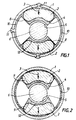
- Figures 1 and 2 illustrate a motor having a fixed inductor exterior according to the present invention and an interior mobile armature.
- the cylinder head made of soft ferromagnetic material
- permanent magnets of hard, non-machined or machined ferromagnetic material briefly with the arrows (3) indicating the direction of the magnetic field.
- the overmolding material (4) contains a soft ferromagnetic product dispersed, represented by the dotted line, in a solid matrix non-magnetic, for example a resin.
- the air gap (5) is good delimited by the overmolding material (4) containing the product soft ferromagnetic and armature (6).
- overmolding was done directly in the cylinder head and we see in the case of Figure 1 that the overmolding material (4) passes through places said cylinder head to form anchor points (11). But in in the case of FIG. 2 the overmolding was carried out outside the cylinder head and the rigid over-molding material / magnets assembly was then introduced into said cylinder head then optionally secured with it by any known means.
- FIG. 3 represents, in an engine of the same type as those of the figures 1 and 2, an inductor according to the invention in which each of the poles is made of several magnets (2) placed side by side, these magnets having more, thanks to the invention, a form of parallelepiped plate lying down.
- Figure 4 shows a case where the cylinder head is in two half-shells (or cylinder arc) (1a) and (1b) and where the overmolding according to the invention coats both the magnets (2) and the two half-shells (1a) and (1b) to get a rigid inductor.
- the junction point between the two half-shells can be located anywhere, relative to the axis of the poles.
- the magnets have been precisely machined from a sintered blank to have a gap with armature of about 0.7mm; they were then put in place and glued into the cylinder head by overmolding with a resin thermosetting so that said magnet-induced air gap is well 0.7mm.
- the overmolding is such that there is no resin veil, covering the polar face of the magnet, located in the air gap. We thus avoid increase the air gap thickness which would be necessary to hold allowance for runout tolerances (cylinder head, armature) or mounting and would lead to a decrease in engine performance.
- non-machined blanks of magnets permanent ones of lower volume then placed in the cylinder head and overmolded using a magnetic permeability composite material 4 based on the same thermosetting resin and in which dispersed iron powder (solid content 40% by volume); the air gap composite / induced overmolding material is the same as in the version standard.
- the thickness of the polar layer is approximately 1mm in places the thinnest, that of the 3mm return zone.
- Version 2 differs from version 1 mainly by an air gap about 0.3mm and thicker magnets but whose volume remains lower than the standard version.
- Table 1 gives the values of the flux, directly linked to the performance of the motors, as a function of the geometric parameters of the magnets and of the air gap value for the different versions.
Abstract
Description
L'invention concerne un inducteur de machine tournante électrique comportant des aimants permanents frittés enrobés dans un liant ferromagnétique.The invention relates to an inductor of an electric rotary machine. comprising sintered permanent magnets coated in a binder ferromagnetic.
Les machines électriques tournantes sont principalement les moteurs électriques ou les générateurs électriques, par exemple pour les auxiliaires automobiles; elles comportent un inducteur qui est généralement le stator mais parfois le rotor.Rotating electrical machines are mainly motors electric or electric generators, for example for automotive auxiliaries; they have an inductor which is usually the stator but sometimes the rotor.
Habituellement un inducteur comprend une culasse, pièce tubulaire cylindrique dont la section droite présente au moins un axe de symétrie et est généralement de forme circulaire, polygonale ou carrée aux angles arrondis.Usually an inductor includes a cylinder head, tubular piece cylindrical whose cross section has at least one axis of symmetry and is generally circular, polygonal or square at the corners rounded.
Sur la paroi intérieure de la culasse en matériau magnétique doux, sont fixés un ou plusieurs aimants permanents en matériau magnétique dur. Ils peuvent être de forme annulaire, une seule pièce aimantée recouvrant le pourtour intérieur de la section droite, ou sous forme de plusieurs pièces aimantées réparties symétriquement sur ledit pourtour; ces pièces peuvent alors avoir une section droite par exemple rectangulaire ou préférentiellement être un secteur de couronne circulaire, ou peuvent avoir au moins une face à section circulaire adaptée à l'induit.On the inner wall of the cylinder head made of soft magnetic material, are fixed one or more permanent magnets made of hard magnetic material. They may be annular in shape, a single magnetic piece covering the inside periphery of the cross section, or in the form of several magnetized parts distributed symmetrically around said periphery; these parts can then have a cross section for example rectangular or preferably be a circular crown sector, or can have at least one face of circular section adapted to the armature.
Lesdits aimants permanents peuvent être des pièces frittées, ou des aimants liés composites, la matière aimantée étant par exemple noyée dans une résine solide. Ils sont tels qu'ils laissent au centre de la culasse un espace dans lequel prend place l'induit de la machine tournante. Said permanent magnets can be sintered parts, or composite bonded magnets, the magnetized material being for example embedded in a solid resin. They are such that they leave in the center of the breech a space in which the armature of the rotating machine takes place.
Des pièces polaires peuvent compléter les aimants permanents du côté de l'induit pour modifier le flux magnétique et améliorer les performances de la machine tournante.Pole pieces can complement the permanent magnets on the side of armature to modify magnetic flux and improve performance of the rotating machine.
La matière active des aimants permanents est de type connu, par exemple ferrite, alliage contenant des terres-rares (comme Nd-Fe-B ou Sm-Co) ou autres matériaux. Les pièces polaires sont en matériau magnétique doux, comme la culasse, par exemple en acier.The active material of the permanent magnets is of known type, for example ferrite, an alloy containing rare earths (such as Nd-Fe-B or Sm-Co) or other materials. The pole pieces are made of soft magnetic material, like the cylinder head, for example steel.
Entre les aimants ou les pièces polaires et l'induit se situe l'espace d'entrefer dont l'épaisseur doit être aussi réduite et régulière que possible. Dans les fabrications de moteurs en série elle est habituellement de l'ordre de 0,6 à 1 mm. Il est difficile d'avoir une épaisseur plus faible compte tenu en particulier que la culasse, à laquelle sont adossés les aimants avec éventuellement leurs pièces polaires, est généralement en acier roulé ou embouti et présente une irrégularité géométrique, due aux tolérances dimensionnelles et de symétrie, qui est cumulée avec celle des autres composants.Between the magnets or the pole pieces and the armature is the space air gap whose thickness must be as reduced and regular as possible. In series engine manufacturing it is usually in the range of 0.6 to 1 mm. It is difficult to have a thinner, taking into account in particular that the cylinder head, which the magnets are backed with possibly their parts polar, is usually rolled or stamped steel and has a geometric irregularity, due to dimensional tolerances and symmetry, which is cumulated with that of the other components.
Pour arriver à ce résultat, il est nécessaire de faire subir à l'aimant un usinage soigné et coûteux. Cet usinage demande en particulier beaucoup de soin lorsque l'aimant est en matériau fritté.To achieve this result, it is necessary to subject the magnet careful and costly machining. This machining in particular requires a lot care when the magnet is made of sintered material.
Cependant il est parfois possible de réaliser des entrefers d'épaisseur réduite jusqu'à 0,3mm en accumulant les précautions d'usinage et d'assemblage des différents composants de l'inducteur, précautions qui sont souvent délicates à réaliser et conduisent à une importante augmentation de coût.However it is sometimes possible to make air gaps of thickness reduced to 0.3mm by accumulating machining precautions and assembly of the different components of the inductor, precautions which are often difficult to carry out and lead to significant cost increase.
Les aimants sont habituellement fixés dans la culasse à l'aide d'agrafes ou épingles amovibles, par maintien dans une cage amagnétique (par ex. en matière plastique) ou par collage ou injection d'une résine amagnétique.The magnets are usually fixed in the cylinder head using staples or removable pins, by holding in a non-magnetic cage (e.g. plastic) or by bonding or injection of a non-magnetic resin.
Il est aussi connu et avantageux pour effectuer le montage des aimants de réaliser une pièce rigide comportant des aimants usinés (avec éventuellement leurs pièces polaires) surmoulés à l'aide d'un matériau amagnétique par exemple de l'aluminium ou une résine thermodurcissable. It is also known and advantageous to carry out the mounting of the magnets of make a rigid part with machined magnets (with their pole pieces) overmolded with a material non-magnetic, for example aluminum or a thermosetting resin.
L'ensemble rigide est ensuite introduit et positionné aisément dans la culasse; il peut également être obtenu en surmoulant les aimants directement dans la culasse.The rigid assembly is then easily introduced and positioned in the cylinder head; it can also be obtained by overmolding the magnets directly into the cylinder head.
Dans tous les cas les aimants sont en contact avec la culasse, ou avec des pièces équivalentes, en matériau ferromagnétique doux, de façon à assurer un circuit continu de flux magnétique entre les aimants indispensable au fonctionnement du moteur.In all cases the magnets are in contact with the cylinder head, or with equivalent parts, made of soft ferromagnetic material, so that ensure a continuous magnetic flux circuit between the magnets essential for engine operation.
Une solution de ce type est connue du brevet FR.2617344. Des aimants composites (4), associés éventuellement à des pièces polaires additionnelles, dont le profil de la face polaire est adaptée et concentrique à l'induit, réalisés à partir d'une poudre de Nd-Fe-B mélangée à un liant ou compactée, sont en contact avec la culasse (1) et sont éventuellement associés à des pièces polaires additionnelles ; ils sont surmoulés dans ladite culasse (1) à l'aide d'une résine qui assure leur fixation grâce aux parties latérales (7); en outre l'aimant se trouve protégé, sur sa face polaire en regard avec l'induit, par un voile de résine (5) d'épaisseur constante d'environ 5 mm contre une atmosphère éventuellement corrosive.A solution of this type is known from patent FR.2617344. Magnets composites (4), possibly associated with pole pieces additional, whose profile of the polar face is adapted and armature concentric, made from Nd-Fe-B powder mixed with a binder or compacted, are in contact with the cylinder head (1) and are possibly associated with additional pole pieces; they are overmolded in said cylinder head (1) using a resin which ensures their fixing thanks to the lateral parts (7); furthermore the magnet turns is protected, on its polar face facing the armature, by a veil resin (5) of constant thickness of about 5 mm against an atmosphere possibly corrosive.
Ainsi dans le mode de réalisation décrit, l'épaisseur d'entrefer aimant/induit sera plus grande que les valeurs habituelles de 0,6 à lmm données ci-dessus puisqu'il faudra y ajouter l'épaisseur de substance amagnétique (5) recouvrant la face polaire de l'aimant; les performances de la machine tournante en seront affectées d'autant, même si la distance séparant la substance amagnétique surmoulée (5) de l'induit est très faible (par exemple 0,3mm).Thus in the embodiment described, the gap thickness magnet / armature will be larger than usual values from 0.6 to lmm given above since it will be necessary to add the thickness of substance non-magnetic (5) covering the pole face of the magnet; performances of the rotating machine will be affected by the same amount, even if the distance separating the overmolded non-magnetic substance (5) from the armature is very weak (e.g. 0.3mm).
Il est également connu du brevet JP-A-60 131055, un aimant lié (4), c'est-à-dire à base d'un matériau magnétique dur dispersé dans un liant thermoplastique, moulé sur l'entière périphérie intérieure de la culasse, ledit aimant comportant également des pôles auxiliaires (3). Là encore le profil de la face polaire de l'aimant est adapté et concentrique à la carcasse et à l'induit et l'entrefer d'épaisseur constante est déterminé uniquement par la distance entre l'aimant et l'induit. Par ailleurs, même si l'épaisseur d'entrefer peut être faible grâce à l'emploi d'un aimant moulé sur la culasse, le moteur verra ses performances réduites à cause de l'emploi dudit aimant moulé.It is also known from patent JP-A-60 131055, a bonded magnet (4), that is to say based on a hard magnetic material dispersed in a binder thermoplastic, molded on the entire inner periphery of the cylinder head, said magnet also comprising auxiliary poles (3). Again the profile of the pole face of the magnet is adapted and concentric to the carcass and armature and the air gap of constant thickness is determined only by the distance between the magnet and the armature. Besides, even if the air gap thickness can be small thanks to the use of a magnet molded on the cylinder head, the engine will see its performance reduced because the use of said molded magnet.
Il est encore connu du brevet FR 2 617 343 un inducteur comportant des
aimants identiques à ceux du brevet précédent FR 2 617 344, c'est-à-dire
des aimants liés dont la face polaire a une forme correspondant à celle
de l'induit ; ces aimants, éventuellement associés à des pièces polaires
additionnelles, sont fixés à la culasse et protégés contre la corrosion à
l'aide d'une enveloppe métallique (en tôle) épousant l'intégralité du
contour des pôles magnétiques formés par les ensembles aimants et pièces
polaires. Comme précédemment l'aimant a une forme adaptée à l'induit, la
distance aimant (ou pôle magnétique)-induit étant constante.It is also known from
Dans un tel montage il doit y avoir concentricité entre l'inducteur et la culasse pour avoir un entrefer aimant-induit le plus réduit possible, ce qui exige montage et usinages soignés des différents composants. Malgré cela l'homme du métier ne s'attend pas à obtenir une épaisseur d'entrefer inférieure à 0,6 mm, comme cela a été déjà vu.In such an assembly there must be concentricity between the inductor and the breech to have the smallest magnet-induced air gap possible, which requires careful assembly and machining of the various components. Despite that the skilled person does not expect to obtain a thickness of air gap less than 0.6 mm, as has already been seen.
Il est encore connu du brevet FR 2 169 938 un inducteur comportant des
aimants plats (110) en contact avec des pièces de trajets de flux (116),
maintenus à l'aide d'un carter surmoulé en matière plastique (16). Ce
carter constitue un entrefer supplémentaire amagnétique entre les aimants
et l'induit ; il a une face concentrique à l'induit et a une épaisseur
5 variable pour compenser le fait que la surface polaire des aimants n'est
pas adaptée et concentrique à l'induit. Un tel inducteur présente, du
fait de cette forme d'aimant, des caractéristiques inférieures à celles
d'un inducteur ayant des aimants adaptés et concentriques à l'induit. En
particulier pour une même puissance, un moteur ayant ce type d'aimant
plat nécessitera une masse plus importante d'aimant et sera de ce fait
beaucoup plus volumineux et cher.It is also known from
Il apparaít donc que les moteurs ayant les meilleures performances sont obtenus avec des inducteurs comportant des aimants usinés ou moulés de façon précise et ainsi adaptés et concentriques à l'induit de façon à réduire le plus possible l'épaisseur d'entrefer et les pertes magnétiques. It therefore appears that the motors having the best performance are obtained with inductors comprising magnets machined or molded from precisely and thus adapted and concentric to the armature so as to minimize air gap thickness and losses magnetic.
Les moteurs ayant les meilleures performances sont par ailleurs ceux qui utilisent des aimants frittés de préférence à des aimants liés, même si ces derniers sont moulés concentriquement à l'induit. En effet un aimant lié a toujours des caractéristiques magnétiques inférieures à celle des aimants frittés à cause de son isotropie cristallographique. Le fait que lesdits aimants liés soient fixés à la culasse par surmoulage à l'aide de polymère plastique ne permet pas de rattraper la différence.The engines with the best performance are also those that use sintered magnets in preference to bonded magnets, even if the latter are molded concentrically with the armature. Indeed a magnet bound always has lower magnetic characteristics than sintered magnets because of its crystallographic isotropy. The fact that said bonded magnets are fixed to the cylinder head by overmolding using plastic polymer does not make up for the difference.
On peut noter également, d'après ce qui précède, que les aimants ou les
pôles magnétiques sont toujours en contact avec la culasse ou avec des
pièces de trajets de flux et que pour obtenir des moteurs ayant des
performances acceptables il est nécessaire d'avoir la plus faible et la
plus régulière épaisseur d'entrefer possible. Pour cela la culasse doit
être concentrique à l'induit de même que les aimants qui y sont fixés.
Ceci entraíne la nécessité d'avoir des tolérances très serrées sur la
culasse, sur l'usinage des aimants et des pièces polaires additionnelles,
sur le montage de ces ensembles et plus généralement sur l'assemblage
inducteur-induit pour en assurer la concentricité.
Le fait de surmouler les aimants ne permet pas de s'affranchir de ces
nécessités, le surmoulage ajoutant par ailleurs, comme cela a déjà été
dit, une épaisseur supplémentaire d'entrefer.It may also be noted, from the above, that the magnets or magnetic poles are always in contact with the cylinder head or with parts of flux paths and that in order to obtain engines having acceptable performance it is necessary to have the smallest and most regular air gap thickness possible. For this the cylinder head must be concentric with the armature as well as the magnets which are fixed there. This leads to the need to have very tight tolerances on the cylinder head, on the machining of the magnets and additional pole pieces, on the mounting of these assemblies and more generally on the inductor-armature assembly to ensure their concentricity.
The fact of overmolding the magnets does not make it possible to overcome these necessities, the overmolding additionally adding, as has already been said, an additional thickness of air gap.
Ainsi lesdits moteurs à aimants frittés et usinés pour correspondre à l'induit et déterminer l'entrefer ont encore des caractéristiques limitées du fait que l'épaisseur d'entrefer est toujours trop importante puisqu'elle doit prendre en compte les tolérances dimensionnelles de la culasse et du montage en général. De plus l'usinage des aimants rend ces moteurs coûteux.Thus said motors with sintered magnets and machined to correspond to the armature and determine the air gap still have characteristics limited because the air gap thickness is always too large since it must take into account the dimensional tolerances of the cylinder head and mounting in general. In addition, the machining of the magnets makes these expensive motors.
Aussi la demanderesse a-t-elle cherché à mettre au point des inducteurs
permettant d'améliorer les performances des moteurs.
Elle a également cherché à en diminuer le coût.The Applicant has therefore sought to develop inductors making it possible to improve the performance of the motors.
It also sought to reduce the cost.
Elle a pour cela en particulier cherché à mettre au point des inducteurs comportant des aimants permanents ne nécessitant qu'un usinage partiel et peu onéreux, par exemple un simple dégrossissage, voir aucun usinage, ou plus généralement des aimants dont la forme n'a pas besoin d'être rigoureuse, tout en permettant au moins le maintien, mais plus généralement une amélioration, des caractéristiques des machines tournantes obtenues.In particular, it sought to develop inductors comprising permanent magnets requiring only partial machining and inexpensive, for example a simple roughing, see no machining, or more generally magnets whose shape does not need to be rigorous, while at least allowing the maintenance, but more generally an improvement in the characteristics of the machines rotations obtained.
Elle a également cherché à mettre au point des inducteurs ne nécessitant pas d'exigences ou de tolérances précises pour le positionnement relatif des aimants ou pôles magnétiques et de la culasse, ou pour la concentricité de la culasse avec l'induit.It has also sought to develop inductors that do not require no specific requirements or tolerances for relative positioning magnets or magnetic poles and the yoke, or for the concentricity of the cylinder head with the armature.
Elle a recherché également à mieux contrôler la dispersion des lignes de flux dans l'entrefer ce qui permet encore d'améliorer les performances individuelles des machines tournantes et aussi l'homogénéité des productions en série de machines, tout en conservant une grande facilité de montage.It also sought to better control the dispersion of the lines of flow in the air gap which further improves performance individual rotating machines and also the homogeneity of series production of machines, while retaining great ease mounting.
Elle a encore cherché à obtenir de faibles entrefers, par exemple d'au plus 0,3mm, tout en conservant les avantages ci-dessus.It also sought to obtain small air gaps, for example at least plus 0.3mm, while retaining the above advantages.
L'invention est un inducteur pour machine tournante électrique comportant une culasse cylindrique creuse ou pleine sur une paroi latérale de laquelle est fixé au moins un aimant ayant une face polaire située en regard d'un induit, caractérisé en ce que l'aimant est fixé à la culasse par un surmoulage enrobant au moins ladite face polaire à l'aide d'un matériau composite de surmoulage comprenant un matériau ferromagnétique dispersé dans un liant solide amagnétique.The invention is an inductor for an electric rotary machine comprising a hollow or solid cylindrical cylinder head on a side wall of which is attached at least one magnet having a pole face located in look of an armature, characterized in that the magnet is fixed to the cylinder head by an overmolding coating at least said polar face using a composite overmolding material comprising a ferromagnetic material dispersed in a non-magnetic solid binder.
L'invention concerne le plus souvent un inducteur comportant une culasse cylindrique creuse sur la paroi intérieure de laquelle le ou les aimants sont fixés. L'induit se trouve alors à l'intérieur de l'inducteur. Mais elle concerne également un inducteur comportant une culasse ou noyau cylindrique, plein ou creux, sur la paroi extérieure duquel le ou les aimants sont fixés. L'induit entoure alors l'inducteur.The invention most often relates to an inductor comprising a cylinder head cylindrical hollow on the inner wall of which the magnet (s) are fixed. The armature is then located inside the inductor. But it also relates to an inductor comprising a cylinder head or core cylindrical, full or hollow, on the outer wall of which the one or more magnets are attached. The armature then surrounds the inductor.
Ainsi l'invention concerne un inducteur que celui-ci soit stator ou rotor et qu'il soit situé à l'extérieur ou à l'intérieur de l'induit. Thus, the invention relates to an inductor whether this is a stator or a rotor and that it is located outside or inside the armature.
L'invention est surtout appliquée à la production en série de générateurs ou moteurs électriques en particulier pour les auxiliaires automobiles, où l'inducteur est généralement le stator.The invention is especially applied to the mass production of generators or electric motors in particular for automobile auxiliaries, where the inductor is usually the stator.
La culasse (ou le noyau) a généralement une section droite avec un centre de symétrie; elle est par exemple de forme polygonale avec des angles arrondis, ou de préférence circulaire (par exemple en forme de tube). Elle est habituellement en matériau ferromagnétique dense, par exemple acier, de façon à boucler les lignes de flux magnétiques.The cylinder head (or core) generally has a cross section with a center of symmetry; it is for example of polygonal shape with angles rounded, or preferably circular (for example in the form of a tube). It is usually made of dense ferromagnetic material, for example steel, so as to complete the magnetic flux lines.
Il n'est cependant pas nécessaire que la culasse ait des tolérances précises ; elle peut ainsi présenter des faux ronds ou des défauts de symétrie ; de même elle peut ne pas être concentrique à l'induit. Ceci représente un avantage car cela simplifie leur mode d'obtention et leur coût.However, the cylinder head does not have to have tolerances precise; it may thus show false rounds or defects in symmetry; similarly it may not be concentric to the armature. This represents an advantage because it simplifies their method of obtaining and their cost.
Selon une configuration préférée de l'invention, l'inducteur comprend plusieurs aimants permanents qui constituent autant de pôles. Ils ont habituellement une forme en tuile canal telle que leur section droite est un secteur de couronne circulaire, dont le diamètre intérieur est adapté à celui de l'induit.According to a preferred configuration of the invention, the inductor comprises several permanent magnets which constitute as many poles. they have usually a channel tile shape such that their cross section is a circular crown sector, with an adapted internal diameter to that of the armature.
Mais l'invention permet également d'utiliser des aimants à section droite rectangulaire, ou carrée, pour obtenir des machines tournantes ayant de très bonnes performances.But the invention also makes it possible to use magnets with a cross section rectangular, or square, to obtain rotating machines with very good performance.
Il n'est pas nécessaire que les aimants soient au contact de la culasse ou des pièces de trajet de flux. De même il n'est pas nécessaire qu'ils soient montés concentriquement à l'induit.The magnets do not have to be in contact with the cylinder head or flow path pieces. Likewise it is not necessary that they are mounted concentrically to the armature.
Ainsi l'invention permet de cumuler l'emploi de composants ayant des tolérances ou des exigences peu contraignantes, donc peu coûteux, et des contraintes d'assemblage allégées également peu exigeantes. Il suffit que la surface de la matière composite de surmoulage faisant face à l'induit et déterminant l'épaisseur d'entrefer soit concentrique à l'induit, ave les meilleures tolérances possibles. Thus the invention makes it possible to combine the use of components having non-restrictive tolerances or requirements, therefore inexpensive, and light assembly constraints also undemanding. It is sufficient that the surface of the composite overmolding material facing the armature and determining the gap thickness is concentric to the armature, with the best possible tolerances.
Les aimants sont de type connu. Ils peuvent être des aimants permanents à base de ferrite ou de terres rares et métal de transition (par ex. Fe-Nd-B ou Sm-Co ...) et peuvent se présenter sous forme de pièces frittées, moulées, obtenues par déformation d'une ébauche ou des pièces composites comprenant le matériau aimanté magnétique dur dispersé dans une matrice solide amagnétique, par exemple une résine. Ils sont habituellement positionnés à proximité de la paroi latérale de la culasse et de façon à ce que leur grand axe soit parallèle à celui de la culasse.The magnets are of known type. They can be permanent magnets to ferrite or rare earth base and transition metal (e.g. Fe-Nd-B or Sm-Co ...) and can be in the form of parts sintered, molded, obtained by deformation of a blank or parts composites comprising the hard magnetic magnet material dispersed in a non-magnetic solid matrix, for example a resin. They are usually positioned near the side wall of the cylinder head and so that their major axis is parallel to that of the cylinder head.
Leur fixation est obtenue grâce au surmoulage. Ce dernier peut être
effectué par injection, extrusion, compaction, moulage, etc... pour
former une pièce rigide qui est ensuite mise en place sur la culasse; le
matériau de surmoulage peut également être mis en oeuvre directement
dans, et éventuellement autour de, la culasse après avoir mis en place
les aimants.
Le matériau de surmoulage enrobe au moins partiellement chacun des
aimants, les maintient en place les uns par rapport aux autres et par
rapport à la culasse. Le surmoulage est tel que les aimants sont répartis
à la surface périphérique de la culasse et qu'il délimite le diamètre de
l'inducteur. C'est ce diamètre complété avec l'épaisseur de l'entrefer
qui donnera le diamètre de l'induit.Their fixing is obtained by overmolding. The latter can be performed by injection, extrusion, compaction, molding, etc ... to form a rigid part which is then placed on the cylinder head; the overmolding material can also be used directly in, and possibly around, the cylinder head after having installed the magnets.
The overmolding material at least partially coats each of the magnets, keeps them in place relative to each other and relative to the cylinder head. Overmolding is such that the magnets are distributed on the peripheral surface of the cylinder head and that it delimits the diameter of the inductor. It is this diameter completed with the thickness of the air gap which will give the diameter of the armature.
Le matériau de surmoulage recouvre la face polaire de l'aimant en regard avec l'induit et puisqu'il contient un matériau ferromagnétique, c'est lui qui assure et règle l'entrefer avec ledit induit. La couche de matière de surmoulage recouvrant la face polaire est appelée couche polaire; elle est la plus mince possible pour éviter les fuites de flux magnétiques transversales ; son épaisseur généralement variable permet de recouvrir les irrégularités de forme de la face polaire et de positionnement des aimants qui ne sont pas concentriques ou adaptés à l'induit ; par contre la face intérieure du surmoulage est adaptée et concentrique à l'induit. L'épaisseur est généralement comprise entre 0,5 et 5mm et de préférence entre 0,5 et 1,5 mm pour les moteurs courants.The overmolding material covers the polar face of the facing magnet with the armature and since it contains a ferromagnetic material, it is he who ensures and regulates the air gap with said armature. The layer of overmolding material covering the polar face is called a layer polar; it is as thin as possible to avoid flow leaks transverse magnetic; its generally variable thickness allows cover the irregularities of shape of the polar face and positioning of magnets which are not concentric or adapted to the armature; on the other hand, the internal face of the overmolding is adapted and concentric to the armature. The thickness is generally between 0.5 and 5mm and preferably between 0.5 and 1.5mm for common engines.
Entre deux aimants consécutifs, on peut disposer un pont (ou zone de retour) de matière composite de surmoulage, qui assure en particulier la rigidité de l'ensemble inducteur, peut éviter de prévoir des points d'ancrage dans la culasse et permet de désaturer la culasse. Il est cependant avantageux d'en réduire la présence au strict minimum ; son épaisseur est de préférence de l'ordre de 1 à 4 mm pour éviter des fuites magnétiques.Between two consecutive magnets, a bridge (or zone of back) of composite overmolding material, which in particular ensures the rigidity of the inductor assembly, can avoid providing points anchor in the cylinder head and allows to desaturate the cylinder head. It is however advantageous to reduce the presence to the strict minimum; his thickness is preferably of the order of 1 to 4 mm to avoid leaks magnetic.
Le matériau composite de surmoulage comprend généralement un métal ferromagnétique doux (par ex. au moins Fe, Co, Ni ou leurs alliages et éventuellement d'autres éléments d'additions connus) dispersé dans un matériau amagnétique solide par exemple une résine ou un liant thermodurcissable ou thermoplastique tels que les polyamides, polyesters, les polyestertéréphtalates (PET), les résines phénoliques, époxy, etc...The composite overmolding material generally comprises a metal soft ferromagnetic (e.g. at least Fe, Co, Ni or their alloys and possibly other known additions) dispersed in a solid non-magnetic material for example a resin or a binder thermosetting or thermoplastic such as polyamides, polyesters, polyesterterephthalates (PET), phenolic resins, epoxy, etc.
La perméabilité magnétique de ce composite est toujours plus grande que 1 puisque le liant amagnétique contient un métal ferromagnétique; elle est généralement supérieure à 2 et de préférence comprise entre 4 et 40.The magnetic permeability of this composite is always greater than 1 since the non-magnetic binder contains a ferromagnetic metal; she is generally greater than 2 and preferably between 4 and 40.
Le taux de métal ferromagnétique se situe de préférence entre 10 et 40% (en volume).The ferromagnetic metal content is preferably between 10 and 40% (in volume).
Il est à noter que des pièces polaires en métal ferromagnétique doux ou des inserts amagnétiques, par ex. de positionnement, peuvent être également noyées dans le matériau de surmoulage selon les besoins.It should be noted that pole pieces made of soft ferromagnetic metal or non-magnetic inserts, e.g. positioning, can be also embedded in the overmolding material as required.
Les aimants permanents peuvent, comme cela a été dit, se contenter d'un usinage réduit ou sommaire pour éliminer les gros défauts, voire aucun usinage. En effet dans l'invention l'épaisseur et la régularité de l'entrefer ne sont pas déterminées par l'intervalle entre un aimant usiné avec précision et l'induit selon l'art antérieur, mais c'est la matière de surmoulage ou d'enrobage contenant le matériau dispersé magnétique doux et mis en forme à des cotes précises qui assure l'entrefer et qui permet de s'affranchir des irrégularités résultant d'un aimant non parfaitement usiné ou positionné ou d'une culasse imparfaite.Permanent magnets can, as has been said, settle for a reduced or summary machining to eliminate large or no defects machining. Indeed in the invention the thickness and regularity of the air gap is not determined by the interval between a machined magnet with precision and armature according to the prior art, but this is the material overmolding or coating containing the magnetic dispersed material soft and shaped to precise dimensions which ensures the air gap and which eliminates irregularities resulting from a non-magnet perfectly machined or positioned or an imperfect cylinder head.
L'invention est ainsi particulièrement adaptée à l'emploi d'aimants permanents frittés non usinés ou de forme rudimentaire ou simple, faciles et moins coûteux à obtenir. En effet la présence du matériau ferromagnétique dans le surmoulage permet de conserver les très bonnes propriétés magnétiques des inducteurs comprenant des aimants frittés usinés sans supporter le coût de leur usinage ou d'une mise en forme élaborée.The invention is thus particularly suitable for the use of magnets permanent sintered, not machined or of rudimentary or simple form, easy and less expensive to obtain. The presence of the material ferromagnetic in the overmolding keeps very good magnetic properties of inductors including sintered magnets machined without bearing the cost of their machining or shaping elaborate.
La présence de matériau ferromagnétique dans le surmoulage enrobant l'aimant permet de régulariser l'induction magnétique dans l'entrefer et de minimiser ainsi la variation de couple de la machine consécutive aux variations brusques d'induction dans l'entrefer due à l'aimant de forme irrégulière ou non adaptée à l'induit. De plus, le surmoulage permet une immobilisation complète et rigide de l'aimant, qui ne génère plus de vibrations mécaniques. Ainsi les bruits d'origine magnétique et mécanique sont considérablement réduits.The presence of ferromagnetic material in the coating overmolding the magnet regulates the magnetic induction in the air gap and thus minimize the variation in torque of the machine following the sudden variations in induction in the air gap due to the shape magnet irregular or not adapted to the armature. In addition, overmolding allows a complete and rigid immobilization of the magnet, which no longer generates mechanical vibrations. Thus noises of magnetic and mechanical origin are greatly reduced.
Le fait de pouvoir mettre en forme aisément le matériau de surmoulage directement à des cotes précises correspondant à l'induit, permet d'obtenir des épaisseurs d'entrefer très réduites toujours inférieures à 0,7mm mais pouvant aisément atteindre ou être inférieures à 0,3mm. En pratique on utilise souvent cette valeur qui représente un bon compromis entre une épaisseur d'entrefer plus faible qui permet une augmentation du couple moteur et une épaisseur plus élevée moins sensible aux irrégularités géométriques et magnétiques du montage.Being able to easily shape the overmolding material directly to precise dimensions corresponding to the armature, allows to obtain very reduced gap thicknesses always less than 0.7mm but can easily reach or be less than 0.3mm. In practical we often use this value which represents a good compromise between a smaller gap thickness which allows an increase in motor torque and a higher thickness less sensitive to geometric and magnetic irregularities of the assembly.
L'invention permet cependant en cas de besoin de réduire encore l'épaisseur d'entrefer sans altérer sensiblement la régularité de fonctionnement de la machine tournante et la constance des caractéristiques lors de la production en série.The invention however makes it possible, if necessary, to further reduce the air gap thickness without appreciably altering the regularity of operation of the rotating machine and the consistency of characteristics during mass production.
Un autre avantage de l'invention réside dans le fait qu'il n'est pas nécessaire d'utiliser une culasse ayant des tolérances serrées ou concentriques à l'induit, de procéder à un positionnement rigoureux des aimants au contact de la culasse ou d'utiliser des aimants reproduisant fidèlement la forme de l'induit ; en effet, à l'inverse de ce qui est nécessaire dans l'art antérieur, ce n'est pas des aimants que dépend l'entrefer mais du matériau de surmoulage.Another advantage of the invention lies in the fact that it is not necessary to use a cylinder head with tight tolerances or concentric to the armature, to carry out a rigorous positioning of the magnets in contact with the cylinder head or using magnets reproducing faithfully the shape of the armature; indeed, unlike what is necessary in the prior art, it is not magnets that depend the air gap but overmolding material.
Quand l'inducteur comprend plusieurs aimants permanents, il est
particulièrement avantageux que les fuites magnétiques se produisant par
les parties latérales du matériau de surmoulage enrobant les bords (le
pourtour) des aimants soient réduites au minimum afin de limiter les
pertes de flux magnétique dans la culasse.
Pour cela on peut réduire au minimum l'épaisseur de cette partie latérale
qui ne dépasse pas en général 1 à 4mm. On peut également la supprimer
complètement, en laissant cependant subsister par endroits des plots de
raccordement en matériau de surmoulage qui contribuent au maintien des
aimants et au raccordement de la couche polaire avec la zone de retour.
Ces parties latérales ou les plots de raccordement peuvent aussi être
réalisés en matériau de surmoulage amagnétique, constituant ainsi un
assemblage composite ferromagnétique et amagnétique des aimants dans la
culasse.When the inductor comprises several permanent magnets, it is particularly advantageous that the magnetic leaks occurring by the lateral parts of the overmolding material coating the edges (the periphery) of the magnets are reduced to the minimum in order to limit the losses of magnetic flux in the cylinder head.
For this we can minimize the thickness of this side part which generally does not exceed 1 to 4mm. It can also be completely eliminated, however leaving in places some connection pads made of overmolding material which contribute to the maintenance of the magnets and to the connection of the polar layer with the return zone. These lateral parts or the connection pads can also be made of non-magnetic overmolding material, thus constituting a composite ferromagnetic and non-magnetic assembly of the magnets in the cylinder head.
D'autres possibilités offertes grâce aux avantages apportés par l'invention consistent par exemple :
- à encombrement du moteur constant et à entrefer également constant, à diminuer le volume d'aimant non usiné pour obtenir un flux sensiblement équivalent à celui d'une structure standard de l'art antérieur utilisant des aimants usinés maintenus dans la culasse par collage, surmoulage amagnétique ou fixation mécanique;
- à encombrement du moteur constant, à diminuer l'entrefer ainsi que le volume d'aimant non usiné pour obtenir un flux supérieur à celui de ladite structure, donc à améliorer les performances de la machine tournante;
- à volume d'aimant constant et à entrefer éventuellement réduit, à accroítre considérablement le flux par rapport à ladite structure standard, donc les performances de la machine tournante;
- à encombrement constant et à entrefer éventuellement réduit, à accroítre le volume d'aimant non usiné en augmentant l'angle de couverture d'un pôle. Habituellement, et spécialement dans le cas des aimants frittés anisotropes ayant la forme de tuile canal, les contraintes de fabrication ne permettent pas de réaliser d'un seul tenant et de manière économique, des aimants présentant un angle de couverture important. Ainsi grâce au surmoulage de l'invention un pôle peut être réalisé en accolant bord à bord plusieurs aimants aimantés dans la même direction; ceci permet d'obtenir facilement des angles de couverture très importants, par exemple dépassant aisément 140 à 160°.
- with constant engine dimensions and also constant air gap, to reduce the volume of non-machined magnet to obtain a flux substantially equivalent to that of a standard structure of the prior art using machined magnets held in the cylinder head by bonding, overmolding non-magnetic or mechanical fixing;
- at constant motor space, to reduce the air gap as well as the volume of non-machined magnet to obtain a flux greater than that of said structure, therefore to improve the performance of the rotary machine;
- with constant magnet volume and possibly reduced air gap, considerably increasing the flux compared to said standard structure, therefore the performance of the rotary machine;
- with constant bulk and possibly reduced air gap, increasing the volume of non-machined magnet by increasing the coverage angle of a pole. Usually, and especially in the case of anisotropic sintered magnets having the shape of a channel tile, the manufacturing constraints do not make it possible to produce in one piece and economically, magnets having a large coverage angle. Thus, thanks to the overmolding of the invention, a pole can be produced by joining several edge-to-edge magnets magnetized in the same direction; this makes it possible to easily obtain very large coverage angles, for example easily exceeding 140 to 160 °.
En effet, la présence du matériau de surmoulage ferromagnétique, particulièrement entre des aimants contigus de même polarité formant le pôle, permet, malgré le fractionnement magnétique du pôle, d'assurer une bonne homogénéité de l'induction magnétique sous le pôle. Cette façon d'augmenter le volume d'aimant est économique et permet des gains de flux et de performances qui peuvent être très importants;
- à constituer, selon la méthode précédente, une couronne circulaire complète à l'aide de plusieurs aimants jointifs maintenus par le surmoulage ferromagnétique et aimantés pour obtenir un nombre quelconque de pôles magnétiques;
- à recouvrir au moins partiellement l'autre paroi latérale de la culasse ne comportant pas les aimants, ce qui permet d'utiliser des culasses réalisées à l'aide d'une simple tôle roulée ou emboutie pour obtenir un cylindre non nécessairement fermé et ayant des tolérances géométriques élargies. Dans ce cas, la culasse cylindrique peut même être réalisée à partir d'arcs de cylindres accolés, l'ensemble étant surmoulé simultanément avec les aimants à l'aide du liant ferromagnétique selon l'invention.
- to constitute, according to the preceding method, a complete circular crown using several contiguous magnets held by the ferromagnetic overmolding and magnetized to obtain any number of magnetic poles;
- to cover at least partially the other side wall of the cylinder head not comprising the magnets, which allows the use of cylinder heads made with a simple rolled or stamped sheet to obtain a cylinder not necessarily closed and having extended geometric tolerances. In this case, the cylindrical yoke can even be produced from arcs of adjoining cylinders, the assembly being overmolded simultaneously with the magnets using the ferromagnetic binder according to the invention.
Les figures 1 et 2 illustrent un moteur possédant un inducteur fixe extérieur selon la présente invention et un induit mobile intérieur.Figures 1 and 2 illustrate a motor having a fixed inductor exterior according to the present invention and an interior mobile armature.
En (1) on voit la culasse, en matériau ferromagnétique doux, en (2) des aimants permanents en matériau ferromagnétique dur non usinés ou usinés sommairement avec les flèches (3) indiquant le sens du champ magnétique. Le matériau de surmoulage (4) contient un produit ferromagnétique doux dispersé, représenté par le pointillé, dans une matrice solide amagnétique, par exemple une résine. On voit que l'entrefer (5) est bien délimité par le matériau de surmoulage (4) contenant le produit ferromagnétique doux et l'induit (6).In (1) we see the cylinder head, made of soft ferromagnetic material, in (2) permanent magnets of hard, non-machined or machined ferromagnetic material briefly with the arrows (3) indicating the direction of the magnetic field. The overmolding material (4) contains a soft ferromagnetic product dispersed, represented by the dotted line, in a solid matrix non-magnetic, for example a resin. We see that the air gap (5) is good delimited by the overmolding material (4) containing the product soft ferromagnetic and armature (6).
Sur les figures 1 et 2, les deux aimants sont séparés l'un de l'autre. Dans la figure 1 le matériau de surmoulage a alors été conformé de façon à ce que les parties latérales (8) enrobant les bords desdits aimants soient suffisamment minces pour éviter des fuites magnétiques trop importantes. Dans la figure 2 les parties latérales ont été supprimées et remplacées par des plots de raccordements (9) en matériau de surmoulage traversant l'aimant par des lumières pratiquées par endroits et assurant la cohésion du surmoulage et des aimants. En (10) on voit une zone de retour étroite assurant la rigidité de l'ensemble matériau de surmoulage/aimants.In Figures 1 and 2, the two magnets are separated from each other. In Figure 1 the overmolding material was then shaped so the side parts (8) coating the edges of said magnets are thin enough to avoid too much magnetic leakage important. In Figure 2 the side parts have been removed and replaced by connection pads (9) made of overmolding material crossing the magnet by lights practiced in places and ensuring the cohesion of the overmolding and the magnets. In (10) we see an area of narrow return ensuring the rigidity of the material assembly overmolding / magnets.
Le surmoulage a été fait directement dans la culasse et on voit dans le cas de la figure 1 que le matériau de surmoulage (4) traverse par endroits ladite culasse pour former des points d'ancrage (11). Mais dans le cas de la figure 2 le surmoulage a été effectué en dehors de la culasse et l'ensemble rigide matériau de surmoulage/aimants a été introduit ensuite dans ladite culasse puis éventuellement solidarisé avec elle par tous moyens connus.The overmolding was done directly in the cylinder head and we see in the case of Figure 1 that the overmolding material (4) passes through places said cylinder head to form anchor points (11). But in in the case of FIG. 2 the overmolding was carried out outside the cylinder head and the rigid over-molding material / magnets assembly was then introduced into said cylinder head then optionally secured with it by any known means.
On voit en (12) la couche polaire en matériau de surmoulage composite qui permet de s'affranchir des irrégularités géométriques des aimants permanents, tout en permettant de régler de façon très précise le diamètre intérieur de l'inducteur et donc à bien maítriser l'épaisseur d'entrefer, en particulier dans le cas des faibles épaisseurs; ceci conduit à améliorer les caractéristiques des machines tournantes tout en facilitant leur construction, y compris lors de la production en série, et en abaisse le prix grâce à l'absence d'usinage précis des aimants.We see in (12) the polar layer of composite overmolding material which eliminates geometric irregularities of the magnets permanent, while allowing very precise adjustment of the inside diameter of the inductor and therefore to control the thickness well air gap, in particular in the case of small thicknesses; this leads to improving the characteristics of rotating machines while facilitating their construction, including during mass production, and lowers the price thanks to the absence of precise machining of the magnets.
La figure 3 représente, dans un moteur de même type que ceux des figures 1 et 2, un inducteur selon l'invention dans lequel chacun des pôles est fait de plusieurs aimants (2) accolés côte à côte, ces aimants ayant de plus, grâce à l'invention, une forme de plaquette parallélépipédique allongée.FIG. 3 represents, in an engine of the same type as those of the figures 1 and 2, an inductor according to the invention in which each of the poles is made of several magnets (2) placed side by side, these magnets having more, thanks to the invention, a form of parallelepiped plate lying down.
La figure 4 représente un cas où la culasse est en deux demi-coquilles (ou arc de cylindre) (1a) et (1b) et où le surmoulage selon l'invention enrobe à la fois les aimants (2) et les deux demi-coquilles (1a) et (1b) pour obtenir un inducteur rigide. Le point de jonction entre les deux demi-coquilles peut être situé n'importe où, par rapport à l'axe des pôles.Figure 4 shows a case where the cylinder head is in two half-shells (or cylinder arc) (1a) and (1b) and where the overmolding according to the invention coats both the magnets (2) and the two half-shells (1a) and (1b) to get a rigid inductor. The junction point between the two half-shells can be located anywhere, relative to the axis of the poles.
On a comparé plusieurs moteurs ayant un encombrement extérieur constant pour ventilateur d'habitacle d'automobile comportant deux poles aimantés en ferrite et une culasse de diamètre 59mm d'une puissance de l'ordre de 150W.We compared several motors with constant external dimensions for automobile interior ventilator with two magnetic poles made of ferrite and a 59mm diameter cylinder head with a power of the order of 150W.
Dans la version standard, selon l'art antérieur, les aimants ont été usinés de façon précise à partir d'une ébauche frittée pour avoir un entrefer avec l'induit d'environ 0,7mm; ils ont été ensuite mis en place et collés dans la culasse par surmoulage à l'aide d'une résine thermodurcissable de façon à ce que ledit entrefer aimant-induit soit bien de 0,7mm.In the standard version, according to the prior art, the magnets have been precisely machined from a sintered blank to have a gap with armature of about 0.7mm; they were then put in place and glued into the cylinder head by overmolding with a resin thermosetting so that said magnet-induced air gap is well 0.7mm.
Le surmoulage est tel qu'il n'y a pas de voile de résine, recouvrant la face polaire de l'aimant, se situant dans l'entrefer. On évite ainsi d'augmenter l'épaisseur d'entrefer ce qui serait nécessaire pour tenir compte des tolérances de faux-rond (culasse, induit) ou de montage et conduirait à une diminution des performances du moteur.The overmolding is such that there is no resin veil, covering the polar face of the magnet, located in the air gap. We thus avoid increase the air gap thickness which would be necessary to hold allowance for runout tolerances (cylinder head, armature) or mounting and would lead to a decrease in engine performance.
Dans la version 1, selon l'invention, des ébauches non usinées d'aimants permanents de volume plus faible puis mises en place dans la culasse et surmoulées à l'aide d'un matériau composite de perméabilité magnétique 4 à base de la même résine thermodurcissable et dans laquelle a été dispersée de la poudre de fer (taux de solide 40% en volume); l'entrefer matériau de surmoulage composite/induit est le même que dans la version standard. L'épaisseur de la couche polaire est d'environ 1mm aux endroits les plus minces, celle de la zone de retour de 3mm. In version 1, according to the invention, non-machined blanks of magnets permanent ones of lower volume then placed in the cylinder head and overmolded using a magnetic permeability composite material 4 based on the same thermosetting resin and in which dispersed iron powder (solid content 40% by volume); the air gap composite / induced overmolding material is the same as in the version standard. The thickness of the polar layer is approximately 1mm in places the thinnest, that of the 3mm return zone.
La version 2 se distingue de la version 1 principalement par un entrefer
de l'ordre de 0,3mm et des aimants plus épais mais dont le volume reste
inférieur à celui de la version standard.
Le tableau 1 donne les valeurs du flux, directement lié à la performance
des moteurs, en fonction des paramètres géométriques des aimants et de la
valeur d'entrefer pour les différentes versions.

En comparant les versions standard et 1, on voit qu'à encombrement extérieur du moteur constant, on gagne prés de 20% de volume d'aimant, alors que les performances du moteur ne sont diminuées que de 3,7%, pertes qui pourraient être aisément compensées par exemple par un léger allongement des aimants. Mais plus avantageusement la comparaison des versions standard et 2 montre que l'invention permet, toujours à encombrement constant, de gagner 12% de volume d'aimant tout en augmentant les performances du moteur grâce à une épaisseur d'entrefer réduite.By comparing the standard versions and 1, we see that with dimensions outside the constant motor, we gain almost 20% of the magnet volume, while engine performance is only reduced by 3.7%, losses which could be easily compensated for example by a slight extension of the magnets. But more advantageously the comparison of standard and 2 versions shows that the invention allows, still to constant size, gain 12% of magnet volume while increasing engine performance thanks to reduced air gap thickness.
Claims (13)
- An inductor for an electric rotary machine comprising a hollow or solid cylindrical yoke (1), on one side wall of which is attached at least one magnet (2) having a pole face disposed facing an armature (6), characterized in that the magnet (2) is attached to the yoke (1) by an over-molding which coats at least said pole face with a composite over-molding material (4) comprising a ferromagnetic material dispersed in a solid non-magnetic binder.
- An inductor according to claim 1, characterized in that the cylindrical yoke (1) is hollow and that the magnet or magnets (2) are attached to its inner side wall, the armature (6) being disposed inside the inductor.
- An inductor according to claim 1, characterized in that the cylindrical yoke (1) is solid or hollow and that the magnet or magnets (2) are attached to its outer side wall, the armature (6) thus surrounding the inductor.
- An inductor according to any of claims 1 through 3, characterized in that the thickness of the air gap (5) is measured between the over-molding material (4) and the armature (6).
- An inductor according to claim 4, characterized in that the thickness of the air gap (5) is always less than 0.7 mm and preferably no more than 0.3 mm.
- An inductor according to any of claims 1 through 5, characterized in that the thickness of the layer (12) of over-molding material (4) covering the polar face of the magnet (2) is between 0.5 and 5 mm.
- An inductor according to any of claims 1 through 6, characterized in that the over-molding material (4) and the magnets (2) form a rigid assembly inserted into the yoke (1) or obtained by the injection, extrusion, compaction or molding of said material into the yoke.
- An inductor according to any of claims 1 through 7, characterized in that the leaks of magnetic flux along the lateral surfaces of the magnets are reduced to a minimum.
- An inductor according to claim 8, characterized in that the thickness (8) of the over-molding material along the lateral surfaces of the magnets is less than 5 mm.
- An inductor according to any of claims 1 through 9, characterized in that the magnets (2) are permanent magnets based on ferrites or on rare earths.
- An inductor according to any of claims 1 through 10, characterized in that the over-molding material (4) has a magnetic permeability greater than 2 and preferably between 4 and 40.
- An inductor according to any of claims 1 through 11, characterized in that the ferromagnetic material dispersed in the non-magnetic binder is a soft ferromagnetic metal containing at least one element from the group Fe, Co, Ni.
- An inductor according to any of claims 1 through 12, characterized in that the solid magnetic binder is based on thermosetting or thermoplastic resin.
Applications Claiming Priority (3)
| Application Number | Priority Date | Filing Date | Title |
|---|---|---|---|
| FR9502009A FR2730874B1 (en) | 1995-02-16 | 1995-02-16 | COMPOSITE INDUCTOR FOR ROTATING ELECTRIC MACHINES COMPRISING SINTERED PERMANENT MAGNETS COATED IN A FERROMAGNETIC BINDER |
| FR9502009 | 1995-02-16 | ||
| PCT/FR1996/000231 WO1996025785A1 (en) | 1995-02-16 | 1996-02-13 | Composite inductor for electric rotary machines comprising sintered permanent magnets coated with a ferromagnetic binder |
Publications (2)
| Publication Number | Publication Date |
|---|---|
| EP0809878A1 EP0809878A1 (en) | 1997-12-03 |
| EP0809878B1 true EP0809878B1 (en) | 1998-10-14 |
Family
ID=9476375
Family Applications (1)
| Application Number | Title | Priority Date | Filing Date |
|---|---|---|---|
| EP96904130A Expired - Lifetime EP0809878B1 (en) | 1995-02-16 | 1996-02-13 | Composite inductor for electric rotary machines comprising sintered permanent magnets coated with a ferromagnetic binder |
Country Status (12)
| Country | Link |
|---|---|
| US (1) | US5861695A (en) |
| EP (1) | EP0809878B1 (en) |
| JP (1) | JPH11500597A (en) |
| KR (1) | KR19980702157A (en) |
| CN (1) | CN1173950A (en) |
| AT (1) | ATE172334T1 (en) |
| BR (1) | BR9607036A (en) |
| DE (1) | DE69600792T2 (en) |
| FR (1) | FR2730874B1 (en) |
| MX (1) | MX9706079A (en) |
| PL (1) | PL321603A1 (en) |
| WO (1) | WO1996025785A1 (en) |
Families Citing this family (39)
| Publication number | Priority date | Publication date | Assignee | Title |
|---|---|---|---|---|
| JP3017953B2 (en) * | 1996-07-24 | 2000-03-13 | 株式会社東芝 | Motor rotor and method of manufacturing the same |
| US6097118A (en) * | 1998-10-30 | 2000-08-01 | University Of Chicago | Reluctance apparatus for flywheel energy storage |
| FR2791483B1 (en) * | 1999-03-22 | 2004-06-25 | Valeo Equip Electr Moteur | ROTATING MACHINE COMPRISING MAGNETS OF DIFFERENT COMPOSITIONS |
| JP2000324769A (en) * | 1999-05-13 | 2000-11-24 | Matsushita Electric Ind Co Ltd | Stepping motor |
| US6522042B1 (en) | 2000-01-27 | 2003-02-18 | Black & Decker Inc. | Anchoring system for injection molded magnets on a flux ring or motor housing |
| CN1298091C (en) * | 2000-01-27 | 2007-01-31 | 布莱克-德克尔公司 | Fixing system for magnet injected and casted on welded ring or electric machine shell |
| US6522041B1 (en) | 2000-03-08 | 2003-02-18 | Black & Decker Inc. | Permanent magnet motor flux rings |
| US6441522B1 (en) | 2000-03-31 | 2002-08-27 | Coleman Powermate, Inc. | Electromagnetic apparatus employing high permeability low conductivity element |
| JP2002010606A (en) * | 2000-06-20 | 2002-01-11 | Honda Motor Co Ltd | Outer rotor brushless dc motor |
| US6462448B1 (en) | 2000-07-05 | 2002-10-08 | Black & Decker Inc. | Flux ring for an electric motor |
| US20050191788A1 (en) * | 2001-02-15 | 2005-09-01 | Integral Technologies, Inc. | Low cost magnetic brakes and motion control devices manufactured from conductive loaded resin-based materials |
| US7273135B2 (en) * | 2001-02-15 | 2007-09-25 | Integral Technologies, Inc. | Low cost magnetic brakes and motion control devices manufactured from conductive loaded resin-based materials |
| US7038343B2 (en) * | 2002-02-22 | 2006-05-02 | Black & Decker Inc. | Field assembly for a motor and method of making same |
| US6903475B2 (en) * | 2001-02-23 | 2005-06-07 | Black & Decker Inc. | Stator assembly with an overmolding that secures magnets to a flux ring and the flux ring to a stator housing |
| KR100766581B1 (en) * | 2001-04-03 | 2007-10-15 | 뉴모텍(주) | Stator of motor molded thermoplastic resin method for manufacturing the same |
| DE10216476A1 (en) * | 2002-04-13 | 2003-10-23 | Bosch Gmbh Robert | Rotor for electrical machine, especially motor, has pressed iron powder rotor body in one piece enclosing permanent magnets with good magnetic conductivity, preferably in 3 main directions |
| JP2006518177A (en) * | 2002-12-13 | 2006-08-03 | ブラック アンド デッカー インク | Stator assembly with overmolding that secures the magnet to the flux ring and the flux ring to the stator housing |
| GB2418544B (en) * | 2002-12-13 | 2006-08-30 | Black & Decker Inc | A stator assembly with an overmolding that secures magnets to a flux ring and the flux ring to a stator housing |
| DE102004002458A1 (en) * | 2004-01-16 | 2005-08-11 | Siemens Ag | Fuel delivery unit |
| US20060127253A1 (en) * | 2004-12-10 | 2006-06-15 | Ekberg Andrew M | Inner drive for magnetic drive pump |
| US20110278966A1 (en) * | 2006-10-13 | 2011-11-17 | Black & Decker Inc. | Motor With Overmolded Permanent Magnets |
| WO2008048486A1 (en) * | 2006-10-13 | 2008-04-24 | Black & Decker Inc. | Anchoring system for a stator housing assembly having an overmolding; power tool with same |
| DE102007005770A1 (en) * | 2006-12-29 | 2008-07-03 | Robert Bosch Gmbh | Motor drive unit for disk wiping device of motor vehicle, has direct current motor with armature rotatably supported in pole housing and permanent magnets provided at housing wall, where magnets stay in reciprocal effect with armature |
| DE102007014348A1 (en) * | 2007-03-26 | 2008-10-02 | Robert Bosch Gmbh | Magnetic holder for an electric motor |
| US7772741B1 (en) * | 2007-11-30 | 2010-08-10 | Rittenhouse Norman P | Wind turbine generator |
| US7579742B1 (en) * | 2008-01-17 | 2009-08-25 | Norman Rittenhouse | High-efficiency parallel-pole molded-magnetic flux channels transverse wound motor-dynamo |
| DE102009031371B4 (en) | 2009-07-01 | 2011-05-26 | Siemens Aktiengesellschaft | Rotor and method of manufacturing a rotor of an electric machine |
| CN102035316B (en) * | 2009-09-27 | 2015-07-08 | 天津市松正电动汽车技术股份有限公司 | Sticking mode for convex rotor core magnetic steel of permanent magnet synchronous motor |
| DE102010043977A1 (en) * | 2010-11-16 | 2012-05-16 | Robert Bosch Gmbh | Electric motor with improved magnet retainer ring, and a method of manufacturing the magnet retainer ring |
| JP5464604B2 (en) * | 2011-09-20 | 2014-04-09 | シナノケンシ株式会社 | Motor rotor and manufacturing method thereof, inner rotor type brushless motor and manufacturing method thereof |
| US8922087B1 (en) | 2013-08-26 | 2014-12-30 | Norman P Rittenhouse | High efficiency low torque ripple multi-phase permanent magnet machine |
| US20160133364A1 (en) * | 2014-11-07 | 2016-05-12 | Ford Global Technologies, Llc | Fixtures and Methods for Forming Aligned Magnetic Cores |
| KR102446182B1 (en) * | 2015-05-27 | 2022-09-22 | 엘지이노텍 주식회사 | Rotor and Motor and using the same |
| CN106936226A (en) * | 2015-12-30 | 2017-07-07 | 联合汽车电子有限公司 | Magnetic steel of motor, motor and throttle body |
| CN105553223B (en) * | 2015-12-30 | 2018-01-23 | 哈尔滨工业大学 | A kind of rotary voice coil motor of double magnetic circuit of special-shaped magnetic steel structure that can be self-positioning |
| FR3069391B1 (en) * | 2017-07-24 | 2021-12-31 | Valeo Equip Electr Moteur | ROTOR WITH PERMANENT MAGNET FOR ELECTRIC MOTOR AND CORRESPONDING AIR PULSE DEVICE |
| FR3069392B1 (en) * | 2017-07-24 | 2020-11-06 | Valeo Equip Electr Moteur | ROTOR WITH PERMANENT MAGNETS FOR ELECTRIC MOTOR AND CORRESPONDING AIR PULSION DEVICE |
| CN109361276A (en) * | 2018-11-05 | 2019-02-19 | 赣州诚正电机有限公司 | A kind of brushless rimless rare-earth permanent-magnet electric machine |
| FR3118346B1 (en) * | 2020-12-17 | 2023-10-20 | Renault Sas | Magnetic pole element for axial flux electric machine rotor |
Family Cites Families (7)
| Publication number | Priority date | Publication date | Assignee | Title |
|---|---|---|---|---|
| US3899702A (en) * | 1971-12-09 | 1975-08-12 | Singer Co | Torquer armature |
| US3789250A (en) * | 1972-02-04 | 1974-01-29 | Ford Motor Co | Permanent magnet dynamoelectric machine |
| DE2835441A1 (en) * | 1978-08-12 | 1980-02-28 | Vacuumschmelze Gmbh | Shell magnet of flat segments prodn. - uses starting, flat, magnetic plate, broken in mould into segments and embedded in suitable plastics substance |
| JPS56112868A (en) * | 1980-02-06 | 1981-09-05 | Matsushita Electric Ind Co Ltd | Small-sized dc motor |
| JPS60131055A (en) * | 1983-12-16 | 1985-07-12 | Hitachi Ltd | Stator of magnet type dc machine and manufacture thereof |
| FR2617343B1 (en) * | 1987-06-23 | 1993-05-21 | Valeo | PERMANENT MAGNET INDUCER POLE AND ELECTRIC ROTATING MACHINE STATOR PROVIDED WITH SUCH POLES |
| FR2617344B1 (en) * | 1987-06-23 | 1993-05-21 | Valeo | ELECTRIC ROTATING MACHINE STATOR WITH PERMANENT MAGNETS |
-
1995
- 1995-02-16 FR FR9502009A patent/FR2730874B1/en not_active Expired - Fee Related
-
1996
- 1996-02-13 US US08/875,109 patent/US5861695A/en not_active Expired - Lifetime
- 1996-02-13 JP JP8524711A patent/JPH11500597A/en not_active Ceased
- 1996-02-13 AT AT96904130T patent/ATE172334T1/en not_active IP Right Cessation
- 1996-02-13 WO PCT/FR1996/000231 patent/WO1996025785A1/en not_active Application Discontinuation
- 1996-02-13 CN CN96191916A patent/CN1173950A/en active Pending
- 1996-02-13 EP EP96904130A patent/EP0809878B1/en not_active Expired - Lifetime
- 1996-02-13 DE DE69600792T patent/DE69600792T2/en not_active Expired - Lifetime
- 1996-02-13 BR BR9607036A patent/BR9607036A/en not_active Application Discontinuation
- 1996-02-13 PL PL96321603A patent/PL321603A1/en unknown
- 1996-02-13 MX MX9706079A patent/MX9706079A/en unknown
- 1996-02-13 KR KR1019970705552A patent/KR19980702157A/en not_active Application Discontinuation
Also Published As
| Publication number | Publication date |
|---|---|
| BR9607036A (en) | 1997-11-04 |
| WO1996025785A1 (en) | 1996-08-22 |
| FR2730874A1 (en) | 1996-08-23 |
| DE69600792T2 (en) | 1999-05-27 |
| US5861695A (en) | 1999-01-19 |
| FR2730874B1 (en) | 1997-03-21 |
| PL321603A1 (en) | 1997-12-08 |
| ATE172334T1 (en) | 1998-10-15 |
| MX9706079A (en) | 1998-02-28 |
| KR19980702157A (en) | 1998-07-15 |
| CN1173950A (en) | 1998-02-18 |
| JPH11500597A (en) | 1999-01-12 |
| EP0809878A1 (en) | 1997-12-03 |
| DE69600792D1 (en) | 1998-11-19 |
Similar Documents
| Publication | Publication Date | Title |
|---|---|---|
| EP0809878B1 (en) | Composite inductor for electric rotary machines comprising sintered permanent magnets coated with a ferromagnetic binder | |
| EP3602742B1 (en) | Magnet structure having a plurality of individual magnets integrated into a mesh structure | |
| EP3738199B1 (en) | Electromagnetic motor or generator with two rotors, four stators and an integrated cooling system | |
| EP0313514B1 (en) | Manufacturing method of a non-slotted stator for an electric motor and electric motor fitted with such a stator | |
| FR2958466A1 (en) | SYNCHRONOUS ROTATING ELECTRIC MACHINE WITH PERMANENT MAGNETS AND FLOW CONCENTRATION | |
| FR2958465A1 (en) | SYNCHRONOUS ROTATING ELECTRIC MACHINE WITH PERMANENT MAGNETS AND FLOW CONCENTRATION | |
| EP3729609B1 (en) | Stator for a motor or electromagnetic generator with individual winding support snap-fitted to an associated tooth | |
| FR2927481A1 (en) | METHOD FOR MOUNTING A MAGNETIC POLE AND ASSOCIATED ROTOR | |
| CA3012399A1 (en) | Rotor for axial flux electromagnetic motor or generator with semi-embedded magnets and axial holding means | |
| FR2617344A1 (en) | Stator of rotating electric machine with permanent magnets | |
| WO2015052432A2 (en) | Slotless electrical machine with concentrated winding | |
| FR2617345A1 (en) | Stator of rotating electric machine with permanent magnets, and field pole intended for this stator | |
| EP2372874B1 (en) | Synchronous rotating electric machine with permanent magnets and flux concentration | |
| FR3001841A1 (en) | ELECTROMAGNETIC ELECTROMAGNETIC MOTOR OR GENERATOR WITH PERMANENT MAGNETS AND WINDING ELEMENTS WITHOUT IRON | |
| FR3008539A1 (en) | ELECTROMAGNETIC ACTUATOR POLYENTREFERS WITH PERMANENT MAGNETS AND WINDING ELEMENTS WITHOUT IRON | |
| WO2019207240A1 (en) | Stator for a rotary electric machine comprising a magnet with optimized volume | |
| FR2617343A1 (en) | Field pole with permanent magnet, and stator of rotating electric machine provided with such poles | |
| WO2022128983A1 (en) | Element with magnetic poles, comprising an assembly of several individual magnets, for the rotor of an axial flux electric machine | |
| EP3465891A1 (en) | Rotor for a rotating electric machine, comprising rare earth magnets having a low dyprosium content | |
| FR3132803A1 (en) | Process for manufacturing a rotor for an electric machine | |
| FR2786041A1 (en) | Stator winding for a rotating electrical machine, particularly electric motors used to drive equipment in motor vehicles | |
| FR3080716A1 (en) | STATOR OF A ROTATING ELECTRIC MACHINE COMPRISING AN OPTIMIZED VOLUME MAGNET | |
| FR2497021A1 (en) | Electro-motor for timepiece - has punched rotor comprising magnetic material with plastic binder | |
| FR3077413A1 (en) | UNITARY MAGNET WITH FORWARD-LOOKING SHAPES INTENDED TO BE PART OF CONTACT AREAS BETWEEN ADJACENT MAGNETS | |
| EP3116100A1 (en) | Over-moulded rotor of a rotating electric machine |
Legal Events
| Date | Code | Title | Description |
|---|---|---|---|
| PUAI | Public reference made under article 153(3) epc to a published international application that has entered the european phase |
Free format text: ORIGINAL CODE: 0009012 |
|
| 17P | Request for examination filed |
Effective date: 19970707 |
|
| AK | Designated contracting states |
Kind code of ref document: A1 Designated state(s): AT CH DE ES FR GB IE IT LI NL |
|
| GRAG | Despatch of communication of intention to grant |
Free format text: ORIGINAL CODE: EPIDOS AGRA |
|
| 17Q | First examination report despatched |
Effective date: 19971219 |
|
| GRAG | Despatch of communication of intention to grant |
Free format text: ORIGINAL CODE: EPIDOS AGRA |
|
| GRAH | Despatch of communication of intention to grant a patent |
Free format text: ORIGINAL CODE: EPIDOS IGRA |
|
| GRAH | Despatch of communication of intention to grant a patent |
Free format text: ORIGINAL CODE: EPIDOS IGRA |
|
| GRAA | (expected) grant |
Free format text: ORIGINAL CODE: 0009210 |
|
| AK | Designated contracting states |
Kind code of ref document: B1 Designated state(s): AT CH DE ES FR GB IE IT LI NL |
|
| PG25 | Lapsed in a contracting state [announced via postgrant information from national office to epo] |
Ref country code: NL Free format text: LAPSE BECAUSE OF FAILURE TO SUBMIT A TRANSLATION OF THE DESCRIPTION OR TO PAY THE FEE WITHIN THE PRESCRIBED TIME-LIMIT Effective date: 19981014 Ref country code: ES Free format text: THE PATENT HAS BEEN ANNULLED BY A DECISION OF A NATIONAL AUTHORITY Effective date: 19981014 Ref country code: AT Free format text: LAPSE BECAUSE OF FAILURE TO SUBMIT A TRANSLATION OF THE DESCRIPTION OR TO PAY THE FEE WITHIN THE PRESCRIBED TIME-LIMIT Effective date: 19981014 |
|
| REF | Corresponds to: |
Ref document number: 172334 Country of ref document: AT Date of ref document: 19981015 Kind code of ref document: T |
|
| REG | Reference to a national code |
Ref country code: CH Ref legal event code: EP |
|
| REF | Corresponds to: |
Ref document number: 69600792 Country of ref document: DE Date of ref document: 19981119 |
|
| REG | Reference to a national code |
Ref country code: IE Ref legal event code: FG4D Free format text: FRENCH |
|
| GBT | Gb: translation of ep patent filed (gb section 77(6)(a)/1977) |
Effective date: 19981218 |
|
| NLV1 | Nl: lapsed or annulled due to failure to fulfill the requirements of art. 29p and 29m of the patents act | ||
| PG25 | Lapsed in a contracting state [announced via postgrant information from national office to epo] |
Ref country code: IE Free format text: LAPSE BECAUSE OF NON-PAYMENT OF DUE FEES Effective date: 19990820 |
|
| PLBE | No opposition filed within time limit |
Free format text: ORIGINAL CODE: 0009261 |
|
| STAA | Information on the status of an ep patent application or granted ep patent |
Free format text: STATUS: NO OPPOSITION FILED WITHIN TIME LIMIT |
|
| 26N | No opposition filed | ||
| REG | Reference to a national code |
Ref country code: IE Ref legal event code: FD4D |
|
| PG25 | Lapsed in a contracting state [announced via postgrant information from national office to epo] |
Ref country code: LI Free format text: LAPSE BECAUSE OF NON-PAYMENT OF DUE FEES Effective date: 20000229 Ref country code: CH Free format text: LAPSE BECAUSE OF NON-PAYMENT OF DUE FEES Effective date: 20000229 |
|
| REG | Reference to a national code |
Ref country code: CH Ref legal event code: PL |
|
| REG | Reference to a national code |
Ref country code: GB Ref legal event code: IF02 |
|
| PGFP | Annual fee paid to national office [announced via postgrant information from national office to epo] |
Ref country code: GB Payment date: 20040126 Year of fee payment: 9 |
|
| PGFP | Annual fee paid to national office [announced via postgrant information from national office to epo] |
Ref country code: FR Payment date: 20040211 Year of fee payment: 9 |
|
| PG25 | Lapsed in a contracting state [announced via postgrant information from national office to epo] |
Ref country code: IT Free format text: LAPSE BECAUSE OF NON-PAYMENT OF DUE FEES;WARNING: LAPSES OF ITALIAN PATENTS WITH EFFECTIVE DATE BEFORE 2007 MAY HAVE OCCURRED AT ANY TIME BEFORE 2007. THE CORRECT EFFECTIVE DATE MAY BE DIFFERENT FROM THE ONE RECORDED. Effective date: 20050213 Ref country code: GB Free format text: LAPSE BECAUSE OF NON-PAYMENT OF DUE FEES Effective date: 20050213 |
|
| GBPC | Gb: european patent ceased through non-payment of renewal fee |
Effective date: 20050213 |
|
| PG25 | Lapsed in a contracting state [announced via postgrant information from national office to epo] |
Ref country code: FR Free format text: LAPSE BECAUSE OF NON-PAYMENT OF DUE FEES Effective date: 20051031 |
|
| REG | Reference to a national code |
Ref country code: FR Ref legal event code: ST Effective date: 20051031 |
|
| PGFP | Annual fee paid to national office [announced via postgrant information from national office to epo] |
Ref country code: DE Payment date: 20100217 Year of fee payment: 15 |
|
| REG | Reference to a national code |
Ref country code: DE Ref legal event code: R119 Ref document number: 69600792 Country of ref document: DE Effective date: 20110901 |
|
| PG25 | Lapsed in a contracting state [announced via postgrant information from national office to epo] |
Ref country code: DE Free format text: LAPSE BECAUSE OF NON-PAYMENT OF DUE FEES Effective date: 20110901 |