EP0809554B1 - Permeable plug consisting of a joint purge brick - Google Patents
Permeable plug consisting of a joint purge brick Download PDFInfo
- Publication number
- EP0809554B1 EP0809554B1 EP95924160A EP95924160A EP0809554B1 EP 0809554 B1 EP0809554 B1 EP 0809554B1 EP 95924160 A EP95924160 A EP 95924160A EP 95924160 A EP95924160 A EP 95924160A EP 0809554 B1 EP0809554 B1 EP 0809554B1
- Authority
- EP
- European Patent Office
- Prior art keywords
- gas
- hollow body
- joint
- interstice
- moulding
- Prior art date
- Legal status (The legal status is an assumption and is not a legal conclusion. Google has not performed a legal analysis and makes no representation as to the accuracy of the status listed.)
- Revoked
Links
- 238000010926 purge Methods 0.000 title description 24
- 239000011449 brick Substances 0.000 title 1
- 238000005266 casting Methods 0.000 claims abstract description 8
- 239000011819 refractory material Substances 0.000 claims abstract description 6
- 150000001875 compounds Chemical class 0.000 claims abstract description 5
- 238000000465 moulding Methods 0.000 claims description 7
- 238000004519 manufacturing process Methods 0.000 claims description 5
- 239000000126 substance Substances 0.000 claims description 2
- 238000000034 method Methods 0.000 claims 1
- 230000000149 penetrating effect Effects 0.000 claims 1
- 238000011010 flushing procedure Methods 0.000 abstract description 2
- 239000007789 gas Substances 0.000 description 39
- 239000004575 stone Substances 0.000 description 13
- 239000002184 metal Substances 0.000 description 3
- 230000000694 effects Effects 0.000 description 2
- 239000000155 melt Substances 0.000 description 2
- 230000003287 optical effect Effects 0.000 description 2
- OKTJSMMVPCPJKN-UHFFFAOYSA-N Carbon Chemical compound [C] OKTJSMMVPCPJKN-UHFFFAOYSA-N 0.000 description 1
- 229910000831 Steel Inorganic materials 0.000 description 1
- 238000007664 blowing Methods 0.000 description 1
- 229910052799 carbon Inorganic materials 0.000 description 1
- 239000000969 carrier Substances 0.000 description 1
- 238000005253 cladding Methods 0.000 description 1
- 238000004140 cleaning Methods 0.000 description 1
- 238000001816 cooling Methods 0.000 description 1
- 238000001035 drying Methods 0.000 description 1
- 230000009969 flowable effect Effects 0.000 description 1
- 230000002093 peripheral effect Effects 0.000 description 1
- 125000006850 spacer group Chemical group 0.000 description 1
- 239000010959 steel Substances 0.000 description 1
Images
Classifications
-
- C—CHEMISTRY; METALLURGY
- C04—CEMENTS; CONCRETE; ARTIFICIAL STONE; CERAMICS; REFRACTORIES
- C04B—LIME, MAGNESIA; SLAG; CEMENTS; COMPOSITIONS THEREOF, e.g. MORTARS, CONCRETE OR LIKE BUILDING MATERIALS; ARTIFICIAL STONE; CERAMICS; REFRACTORIES; TREATMENT OF NATURAL STONE
- C04B38/00—Porous mortars, concrete, artificial stone or ceramic ware; Preparation thereof
- C04B38/06—Porous mortars, concrete, artificial stone or ceramic ware; Preparation thereof by burning-out added substances by burning natural expanding materials or by sublimating or melting out added substances
- C04B38/063—Preparing or treating the raw materials individually or as batches
- C04B38/0635—Compounding ingredients
- C04B38/0645—Burnable, meltable, sublimable materials
- C04B38/065—Burnable, meltable, sublimable materials characterised by physical aspects, e.g. shape, size or porosity
-
- B—PERFORMING OPERATIONS; TRANSPORTING
- B22—CASTING; POWDER METALLURGY
- B22D—CASTING OF METALS; CASTING OF OTHER SUBSTANCES BY THE SAME PROCESSES OR DEVICES
- B22D1/00—Treatment of fused masses in the ladle or the supply runners before casting
- B22D1/002—Treatment with gases
- B22D1/005—Injection assemblies therefor
-
- B—PERFORMING OPERATIONS; TRANSPORTING
- B28—WORKING CEMENT, CLAY, OR STONE
- B28B—SHAPING CLAY OR OTHER CERAMIC COMPOSITIONS; SHAPING SLAG; SHAPING MIXTURES CONTAINING CEMENTITIOUS MATERIAL, e.g. PLASTER
- B28B7/00—Moulds; Cores; Mandrels
- B28B7/16—Moulds for making shaped articles with cavities or holes open to the surface, e.g. with blind holes
- B28B7/18—Moulds for making shaped articles with cavities or holes open to the surface, e.g. with blind holes the holes passing completely through the article
Definitions
- the invention relates to a gas purging plug for metallurgical Vessels, with a refractory molded part, in which at least one Gas passage channel is provided in the form of a joint that it from the cold to the hot side.
- joint flushers denotes and are used for blowing reaction or cleaning gases in molten metal.
- the known gas purging stones consist, for example, of a inner, conical fireproof molding, over the a second, outer, also conical shaped part is set.
- Such stones are therefore not constructed as a monoblock.
- the lateral peripheral wall and the bottom area of such Gas purging plugs are usually sealed with a gas-tight one Provide sheet metal cladding, the bottom of which is towards the bottom or Cold side of the gas purging plug is spaced and on this Forms a gas supply space. Located in the floor pan the welded gas supply pipe that is in the gas supply space flows.
- From DE-OS 43 12 988 is also a gas purging plug known in which the gas passage channels with the help of a spatial network structure that are formed inside the monolithically cast refractory molded part with the help a clamping device are generated.
- this gas purging plug is relatively complex, in addition, the inner gas passages are relative long, so that comparatively high pressure losses occur.
- the invention has for its object a gas purging plug to create, the manufacture of which is simplified.
- This gas purging plug can thus be produced according to the invention be that an open hollow body from a meltable or burnable substance, the side wall of which is flat Has openings in one of the outer shape of the molded part appropriate mold is used and that the Side wall of the hollow body while filling the mold with a refractory casting compound is poured, the upper or lower wall areas of the hollow body, the cold and / or Penetrate the hot side of the molded part.
- the gas purging device therefore has a directional one Porosity, with features of a joint washer and one Has gas purging stones with individual gas passage channels.
- the Contrary to the well-known joint washers are inside the joint flat bridges made of refractory material, which the connect opposite joint walls monolithically. Due to the monolithic manufacture, this stone exhibits excellent durability, with the amount of in the Melt gas to be injected in a simple manner through the Thickness of the joint or the size and number of those lying in the joint Bridges depending on the operating pressure of the purge gas can be set precisely.
- the gas purging stones according to the invention can be produced in that an open hollow body, for example made of plastic, in a corresponding mold is used.
- the open hollow body can e.g. B. from a there are conical sleeves, the side walls of which are pierced are.
- the sleeve is placed on the bottom of the mold, which then without further fixation of the hollow body up to whose upper wall areas can be cast completely.
- the the bottom side in the mold later forms the hot side of the sink.
- the wear resistance of such sink stones can be easier Way increased by the fact that the joint and the outer the gas purging plug, for example with the help of carbon carriers be impregnated.
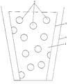
- the drawing figure shows the front view of a conical, hollow body 1 open at the top, on the side wall 2 a A large number of approximately circular openings are present.
- the conical hollow body 1 is used to manufacture the gas purging plug in a likewise conical mold 4 approximately in the middle used. Then the mold with a flowable Refilled refractory mass, the supply of the Casting compound take place inside and outside the hollow body 1 can. The casting compound passes through the openings 3 when pouring through, so that 3 corresponding in the openings Form bridges that the opposite sides of the joint or Support the gas passage duct walls against each other.
- the poured mass as is customary in the prior art, vibrated and compressed.
Landscapes
- Engineering & Computer Science (AREA)
- Chemical & Material Sciences (AREA)
- Ceramic Engineering (AREA)
- Mechanical Engineering (AREA)
- Materials Engineering (AREA)
- Structural Engineering (AREA)
- Organic Chemistry (AREA)
- Manufacturing & Machinery (AREA)
- Treatment Of Steel In Its Molten State (AREA)
- Carbon Steel Or Casting Steel Manufacturing (AREA)
- Furnace Charging Or Discharging (AREA)
- Taps Or Cocks (AREA)
- Physical Or Chemical Processes And Apparatus (AREA)
- Non-Disconnectible Joints And Screw-Threaded Joints (AREA)
- Joints Allowing Movement (AREA)
- Continuous Casting (AREA)
Abstract
Description
Die Erfindung betrifft einen Gasspülstein für metallurgische Gefäße, mit einem Feuerfestformteil, in dem mindestens ein Gasdurchtrittskanal in Form einer Fuge vorgesehen ist, die es von der Kalt- zur Heißseite durchzieht.The invention relates to a gas purging plug for metallurgical Vessels, with a refractory molded part, in which at least one Gas passage channel is provided in the form of a joint that it from the cold to the hot side.
Gattungsgemäße Gasspülsteine werden als sogenannte Fugenspüler bezeichnet und dienen zum Einblasen von Reaktions- oder Reinigungsgasen in Metallschmelzen.Generic gas purging stones are known as joint flushers denotes and are used for blowing reaction or cleaning gases in molten metal.
In der Regel werden sie dabei in die Feuerfestausmauerung eines metallurgischen Gefäßes, insbesondere einer Stahlpfanne, im Bodenbereich eingesetzt und mittels eines Gaszuführungsrohres mit Druckgas beaufschlagt.As a rule, they are in the refractory lining a metallurgical vessel, in particular a steel pan, used in the floor area and by means of a gas supply pipe pressurized with gas.
Die bekannten Gasspülsteine bestehen beispielsweise aus einem inneren, konisch ausgebildeten feuerfesten Formteil, über das ein zweites, äußeres, ebenfalls konisch ausgebildetes Formteil gesetzt wird.The known gas purging stones consist, for example, of a inner, conical fireproof molding, over the a second, outer, also conical shaped part is set.
Um einen definierten Spalt zwischen dem inneren und äußeren Formteil zu gewährleisten, werden in die entsprechende Fuge z. B. streifenförmige Abstandshalter eingesetzt.A defined gap between the inner and outer To ensure molding, z. B. strip-shaped spacers are used.
Derartige Steine sind also nicht als Monoblock aufgebaut.Such stones are therefore not constructed as a monoblock.
Die seitliche Umfangswandung und der Bodenbereich derartiger Gasspülsteine ist üblicherweise mit einer gasdicht verschweißten Blechumkleidung versehen, dessen Boden zur Unterseite bzw. Kaltseite des Gasspülsteins beabstandet ist und auf diese Weise einen Gaszuführungsraum bildet. Im Bodenblech befindet sich das angeschweißte Gaszuführungsrohr, das im Gaszuführungsraum mündet.The lateral peripheral wall and the bottom area of such Gas purging plugs are usually sealed with a gas-tight one Provide sheet metal cladding, the bottom of which is towards the bottom or Cold side of the gas purging plug is spaced and on this Forms a gas supply space. Located in the floor pan the welded gas supply pipe that is in the gas supply space flows.
Bei einem weiteren bekannten Gasspülstein ist die Fuge zwischen der seitlichen Blechummantelung und dem Feuerfestformkörper ausgebildet. Diese Gasspülsteine werden jedoch aufgrund eines relativ geringen Verschleißwiderstandes heute in der Regel nicht mehr verwendet.In another known gas purging plug, the joint is between the lateral sheet metal casing and the refractory molded body educated. However, these gas purging stones are due a relatively low wear resistance today in the Usually no longer used.
Aus der DE-OS 43 12 988 ist darüber hinaus ein Gasspülstein bekannt, bei dem die Gasdurchtrittskanäle mit Hilfe einer räumlichen Netzstruktur gebildet werden, die im Inneren des monolithisch abgegossenen feuerfesten Formteils mit Hilfe einer Spannvorrichtung erzeugt werden.From DE-OS 43 12 988 is also a gas purging plug known in which the gas passage channels with the help of a spatial network structure that are formed inside the monolithically cast refractory molded part with the help a clamping device are generated.
Die Herstellung dieses Gasspülsteins ist jedoch relativ aufwendig, außerdem sind die inneren Gasdurchtrittskanäle relativ lang, so daß vergleichsweise hohe Druckverluste auftreten.However, the production of this gas purging plug is relatively complex, in addition, the inner gas passages are relative long, so that comparatively high pressure losses occur.
Bei einem weiteren, beispielsweise aus der DE-OS 38 23 897 bekannten Spüler werden ebenfalls mit Hilfe einer Spannvorrichtung Fäden bzw. Bänder in eine Gießform eingesetzt, die nach dem Abbinden des Formteiles herausgezogen oder ausgebrannt werden können. Auch dieses Formteil ist als Monoblock hergestellt, das Spannen der einzelnen Fäden ist jedoch wiederum vergleichsweise aufwendig.In another, for example from DE-OS 38 23 897 Known dishwashers are also using a tensioning device Threads or tapes inserted into a mold, the pulled or burned out after the molded part has set can be. This molded part is also a monoblock produced, but the tension of the individual threads is again comparatively complex.
Der Erfindung liegt die Aufgabe zugrunde, einen Gasspülstein zu schaffen, dessen Herstellung vereinfacht ist.The invention has for its object a gas purging plug to create, the manufacture of which is simplified.
Diese Aufgabe wird dadurch gelöst, daß in der Fuge flächige Brücken aus Feuerfestmaterial vorgesehen sind, die die gegenüberliegenden Fugenwandungen einstückig bzw. monolithisch miteinander verbinden.This object is achieved in that flat in the joint Bridges made of refractory material are provided, which are the opposite Joint walls in one piece or monolithic connect with each other.
Dieser Gasspülstein kann erfindungsgemäß dadurch hergestellt werden, daß ein offener Hohlkörper aus einer ausschmelzbaren oder ausbrennbaren Substanz, dessen Seitenwandung flächige Durchbrüche aufweist, in eine der äußeren Gestalt des Formteiles entsprechende Gießform eingesetzt wird und daß die Seitenwandung des Hohlkörpers unter Auffüllen der Gießform mit einer feuerfesten Gießmasse umgossen wird, wobei die oberen bzw. unteren Wandungsbereiche des Hohlkörpers die Kalt- und/oder Heißseite des Formteiles durchdringen. This gas purging plug can thus be produced according to the invention be that an open hollow body from a meltable or burnable substance, the side wall of which is flat Has openings in one of the outer shape of the molded part appropriate mold is used and that the Side wall of the hollow body while filling the mold with a refractory casting compound is poured, the upper or lower wall areas of the hollow body, the cold and / or Penetrate the hot side of the molded part.
Der erfindungsgemäße Gasspüler weist also eine gerichtete Porosität auf, wobei er Merkmale eines Fugenspülers und eines Gasspülsteins mit einzelnen Gasdurchtrittskanälen aufweist. Im Gegensatz zu den bekannten Fugenspülern befinden sich im Inneren der Fuge flächige Brücken aus Feuerfestmaterial, die die gegenüberliegenden Fugenwandungen monolithisch verbinden. Aufgrund der monolithischen Herstellung weist dieser Stein eine hervorragende Haltbarkeit auf, wobei die Menge des in die Schmelze einzudüsenden Gases in einfacher Weise durch die Dicke der Fuge bzw. die Größe und Anzahl der in der Fuge liegenden Brücken in Abhängigkeit vom Betriebsdruck des Spülgases genau eingestellt werden kann.The gas purging device according to the invention therefore has a directional one Porosity, with features of a joint washer and one Has gas purging stones with individual gas passage channels. in the Contrary to the well-known joint washers are inside the joint flat bridges made of refractory material, which the connect opposite joint walls monolithically. Due to the monolithic manufacture, this stone exhibits excellent durability, with the amount of in the Melt gas to be injected in a simple manner through the Thickness of the joint or the size and number of those lying in the joint Bridges depending on the operating pressure of the purge gas can be set precisely.
Durch die flächigen Brücken im Inneren der Fuge können darüber hinaus bereits im Gasspülstein Wirbel hervorgerufen werden, die dazu führen, daß das Gas die Heißseite des Spülers im turbulenten Strömungszustand verläßt und sich auf diese Weise im Inneren der Schmelze fein verteilt.Due to the flat bridges inside the joint, you can use it vortexes are already caused in the gas purging stone, which cause the gas to the hot side of the dishwasher in leaves turbulent flow state and this way finely distributed inside the melt.
Dadurch wird nicht nur die Spülwirkung des eingedüsten Gases verbessert, gleichzeitig wird auch verhindert, daß sich im Bereich der Heißseite des Spülers zu hohe Strömungsgeschwindigkeiten ergeben, die anderenfalls zu einem verstärkten Verschleiß des Gasspülsteines führen würden.This not only reduces the flushing effect of the injected gas improved, at the same time it is prevented that in Area of the hot side of the washer too high flow rates otherwise result in increased wear of the gas purging stone.
Um die Menge von eingedüstem Gas zu erhöhen, können mehrere Fugen vorgesehen sein, die z. B. in konzentrischen Kreisen oder Teilkreisen auf der Heißseite des Spülers münden. Auch läßt sich bei dem erfindungsgemäßen Gasspülstein eine optische Verschleißanzeige in einfacher Weise dadurch verwirklichen, daß z. B. im unteren inneren Bereich des Gasspülsteines eine Fuge ausgebildet ist, die sich zunächst nicht bis zur Heißseite durchzieht, sondern im unteren Bereich endet. Wenn der Gasspülstein bis zu diesem Bereich abgearbeitet ist, ist durch die Kühlwirkung des durch diese Fuge strömenden Gases dann ein innerer dunklerer Bereich zu erkennen, der so den Verschleißzustand des Steines optisch anzeigt. Gasspülsteine mit einer optischen Verschleißanzeige sind z. B. aus der europäischen Patentanmeldung 0 325 709 bekannt.To increase the amount of gas injected, several Joints are provided which, for. B. in concentric circles or partial circles on the hot side of the dishwasher. Also can be an optical in the gas purging plug according to the invention Realize wear indicator in a simple manner by that z. B. in the lower inner region of the gas purging plug Groove is formed, which is initially not up to the hot side runs through, but ends in the lower area. If the Gas purging stone is worked through to this area is through then the cooling effect of the gas flowing through this joint inner darker area can be seen, so the wear condition of the stone visually. Gas purging stones with one optical wear indicator are e.g. B. from the European Patent application 0 325 709 known.
Wie bereits erwähnt, können die erfindungsgemäßen Gasspülsteine dadurch hergestellt werden, daß ein offener Hohlkörper, beispielsweise aus Kunststoff, in eine entsprechende Gießform eingesetzt wird. Der offene Hohlkörper kann z. B. aus einer konischen Hülse bestehen, deren Seitenwandungen durchbrochen sind. Die Hülse wird auf den Boden der Gießform aufgesetzt, die anschließend ohne weitere Fixierung des Hohlkörpers bis zu dessen oberen Wandungsbereichen vollgegossen werden kann. Die in der Gießform unten liegende Seite bildet später die Heißseite des Spülsteines.As already mentioned, the gas purging stones according to the invention can be produced in that an open hollow body, for example made of plastic, in a corresponding mold is used. The open hollow body can e.g. B. from a there are conical sleeves, the side walls of which are pierced are. The sleeve is placed on the bottom of the mold, which then without further fixation of the hollow body up to whose upper wall areas can be cast completely. The the bottom side in the mold later forms the hot side of the sink.
Nach dem Abbinden des Feuerfestmaterials bzw. beim Trocknen wird dann der Kunststoff ausgebrannt oder ausgeschmolzen und hinterläßt die gewünschten Hohlräume, wobei die gegenüberliegenden Wandungen der Fuge durch die flächigen Durchbrüche des Hohlkörpers monolithisch miteinander verbunden sind.After the refractory material has set or when drying the plastic is then burned out or melted out and leaves the desired cavities, with the opposite Walls of the joint through the flat openings of the Hollow body are connected monolithically.
Der Verschleißwiderstand derartiger Spülsteine kann in einfacher Weise dadurch erhöht werden, daß die Fuge und das äußere des Gasspülsteins beispielsweise mit Hilfe von Kohlenstoffträgern imprägniert werden.The wear resistance of such sink stones can be easier Way increased by the fact that the joint and the outer the gas purging plug, for example with the help of carbon carriers be impregnated.
Die Erfindung ist in der Zeichnung beispielsweise veranschaulicht und wird im nachfolgenden anhand der Zeichnung im einzelnen beschrieben.The invention is illustrated in the drawing, for example and will be described in detail below with reference to the drawing described.
Die Zeichnungsfigur zeigt die Vorderansicht eines konischen, oben offenen Hohlkörpers 1, auf dessen Seitenwandung 2 eine Vielzahl von etwa kreisförmigen Durchbrüchen vorhanden sind.The drawing figure shows the front view of a conical, hollow body 1 open at the top, on the side wall 2 a A large number of approximately circular openings are present.
Der konische Hohlkörper 1 wird zur Herstellung des Gasspülsteines
in eine ebenfalls konische Gießform 4 etwa mittig
eingesetzt. Anschließend wird die Gießform mit einer fließfähigen
Feuerfestmasse aufgefüllt, wobei die Zuführung der
Gießmasse im Inneren und außerhalb des Hohlkörpers 1 erfolgen
kann. Die Gießmasse tritt durch die Durchbrüche 3 beim Abgießen
durch, so daß sich in den Durchbrüchen 3 entsprechende
Brücken bilden, die die gegenüberliegenden Fugenseiten bzw.
Gasdurchtrittskanalwandungen gegeneinander abstützen. Die
abgegossene Masse kann dabei, wie beim Stand der Technik üblich,
vibriert und verdichtet werden.The conical hollow body 1 is used to manufacture the gas purging plug
in a likewise conical mold 4 approximately in the middle
used. Then the mold with a flowable
Refilled refractory mass, the supply of the
Casting compound take place inside and outside the hollow body 1
can. The casting compound passes through the
Claims (3)
- Gas-porous plug for metallurgical vessels, comprising a refractory moulding, in which at least one gas passage duct is provided in the form of an interstice running through it from the cold to the hot side, characterised in that flat bridges made of refractory material are provided in the interstice, connecting the opposite walls of the interstice in a single piece, i.e. monolithically.
- Gas-porous plug as per Claim 1, characterised in that at least one second interstice is formed in the interior of the moulding, whose opposite walls are connected monolithically, i.e. in a single piece, by flat bridges made of refractory material, where the interstice ends at a distance from the hot side of the moulding.
- Process for the manufacture of a gas-porous plug as per Claim 1 or 2, characterised in that at least one open hollow body (1) made of a substance which can be burnt or melted out, and whose side wall (2) displays flat apertures (3), is inserted into a casting mould (4) corresponding to the outer form of the moulding, and that the side wall (2) of the hollow body (1) is cast-in when the casting mould (4) is filled with a refractory casting compound, the upper and lower wall areas of the hollow body penetrating the cold and/or hot side of the later moulding.
Applications Claiming Priority (3)
| Application Number | Priority Date | Filing Date | Title |
|---|---|---|---|
| DE19504941A DE19504941C2 (en) | 1995-02-15 | 1995-02-15 | Gas purging stone |
| DE19504941 | 1995-02-15 | ||
| PCT/DE1995/000848 WO1996025259A1 (en) | 1995-02-15 | 1995-06-28 | Gas sink in the form of an interstitial flushing device |
Publications (2)
| Publication Number | Publication Date |
|---|---|
| EP0809554A1 EP0809554A1 (en) | 1997-12-03 |
| EP0809554B1 true EP0809554B1 (en) | 1998-08-19 |
Family
ID=7753954
Family Applications (1)
| Application Number | Title | Priority Date | Filing Date |
|---|---|---|---|
| EP95924160A Revoked EP0809554B1 (en) | 1995-02-15 | 1995-06-28 | Permeable plug consisting of a joint purge brick |
Country Status (9)
| Country | Link |
|---|---|
| US (1) | US5855843A (en) |
| EP (1) | EP0809554B1 (en) |
| AT (1) | ATE169848T1 (en) |
| BR (1) | BR9510450A (en) |
| CA (1) | CA2212715A1 (en) |
| DE (2) | DE19504941C2 (en) |
| ES (1) | ES2121401T3 (en) |
| RU (1) | RU2127650C1 (en) |
| WO (1) | WO1996025259A1 (en) |
Families Citing this family (6)
| Publication number | Priority date | Publication date | Assignee | Title |
|---|---|---|---|---|
| DE19701806C2 (en) * | 1997-01-21 | 1998-11-19 | Didier Werke Ag | Use of a wire mesh |
| DE19846524A1 (en) * | 1998-10-09 | 2000-04-13 | Knoellinger Keramische Erzeugn | Flushing stone used in the refractory wall of a metallurgical vessel has a seam formed between an outer stone and an inner stone |
| JP3126122B1 (en) * | 1999-08-19 | 2001-01-22 | 東京窯業株式会社 | Gas blowing plug and method of manufacturing the same |
| DE10140667C1 (en) * | 2001-08-24 | 2003-03-13 | Ekw Eisenberger Klebsand Werke | Fireproof blow lance and process for its manufacture |
| EP2111938B1 (en) * | 2008-04-24 | 2017-04-19 | Calderys France | Purging plug for blowing gas into a metal treatment recipient |
| CN203265622U (en) * | 2011-11-03 | 2013-11-06 | 维苏维尤斯·克鲁斯布公司 | Apparatus blowing air into metallurgy container and same |
Family Cites Families (14)
| Publication number | Priority date | Publication date | Assignee | Title |
|---|---|---|---|---|
| GB2175830B (en) * | 1985-06-07 | 1988-07-20 | Labate Michael D | Device for introducing gas into a mass of molten metal in a container |
| DE3538498A1 (en) * | 1985-10-30 | 1987-05-07 | Didier Werke Ag | INJECTING DEVICE FOR METALLURGICAL VESSELS |
| DE3625117C1 (en) * | 1986-07-25 | 1987-11-26 | Didier Werke Ag | Gas-flushing cone |
| DE8700662U1 (en) * | 1986-12-13 | 1987-04-23 | Burbach & Bender Ohg Esb Schweissbetrieb, 5900 Siegen | Gas purging plug for metallurgical vessels |
| DE3802657C1 (en) * | 1988-01-29 | 1989-09-21 | Didier-Werke Ag, 6200 Wiesbaden, De | |
| DE3823897A1 (en) * | 1988-07-14 | 1990-01-18 | Plibrico Co Gmbh | Apparatus and process for producing refractory blocks |
| DE3831726C1 (en) * | 1988-09-17 | 1989-10-26 | Plibrico Co Gmbh, 4000 Duesseldorf, De | Process for producing a moulded brick in the shape of a truncated cone for gas bubble bricks |
| DE3907500C1 (en) * | 1989-03-08 | 1990-08-23 | Radex-Heraklith Industriebeteiligungs Ag, Wien, At | Gas bubble brick with directed porosity and method for its manufacture |
| US5156801A (en) * | 1990-06-04 | 1992-10-20 | Refractory Services Corp. | Low porosity-high density radial burst refractory plug with constant flow |
| US5225143A (en) * | 1991-02-01 | 1993-07-06 | Insul Company, Inc. | Device for directional gas distribution into molten metal |
| CA2091280C (en) * | 1991-06-18 | 1996-06-11 | Michael D. Ii Labate | Device for directional gas distribution into molten metal |
| US5249778A (en) * | 1992-04-14 | 1993-10-05 | Dolomitwerke Gmbh | Gas stir plug device with visual wear indicator |
| US5423521A (en) * | 1992-05-19 | 1995-06-13 | Quigley Company, Inc. | Ceramic plug gas distribution device |
| DE4312988A1 (en) * | 1993-04-21 | 1994-10-27 | Didier Werke Ag | Refractory ceramic moulding and production process |
-
1995
- 1995-02-15 DE DE19504941A patent/DE19504941C2/en not_active Revoked
- 1995-06-28 EP EP95924160A patent/EP0809554B1/en not_active Revoked
- 1995-06-28 RU RU97115370A patent/RU2127650C1/en active
- 1995-06-28 BR BR9510450A patent/BR9510450A/en not_active Application Discontinuation
- 1995-06-28 AT AT95924160T patent/ATE169848T1/en not_active IP Right Cessation
- 1995-06-28 US US08/894,220 patent/US5855843A/en not_active Expired - Lifetime
- 1995-06-28 WO PCT/DE1995/000848 patent/WO1996025259A1/en not_active Ceased
- 1995-06-28 DE DE59503292T patent/DE59503292D1/en not_active Expired - Fee Related
- 1995-06-28 CA CA002212715A patent/CA2212715A1/en not_active Abandoned
- 1995-06-28 ES ES95924160T patent/ES2121401T3/en not_active Expired - Lifetime
Also Published As
| Publication number | Publication date |
|---|---|
| DE59503292D1 (en) | 1998-09-24 |
| EP0809554A1 (en) | 1997-12-03 |
| DE19504941C2 (en) | 1998-05-20 |
| CA2212715A1 (en) | 1996-08-22 |
| ES2121401T3 (en) | 1998-11-16 |
| BR9510450A (en) | 1998-05-19 |
| WO1996025259A1 (en) | 1996-08-22 |
| ATE169848T1 (en) | 1998-09-15 |
| RU2127650C1 (en) | 1999-03-20 |
| US5855843A (en) | 1999-01-05 |
| DE19504941A1 (en) | 1996-08-22 |
Similar Documents
| Publication | Publication Date | Title |
|---|---|---|
| EP0630712B1 (en) | Immersion nozzle | |
| DE1508753B1 (en) | pouring tube for a low pressure pouring device | |
| DE3420835C2 (en) | Ceramic sink | |
| EP0809554B1 (en) | Permeable plug consisting of a joint purge brick | |
| DE3628066C2 (en) | Dipping spout and method for making a diving spout | |
| EP1101825B1 (en) | Refractory, ceramic gas flushing brick | |
| DE3907500C1 (en) | Gas bubble brick with directed porosity and method for its manufacture | |
| DE4231686C2 (en) | Closure plate for a slide closure on a container containing a molten metal | |
| DE3433123C2 (en) | Blow stone for metallurgical ladles and method of inserting it into the lining | |
| DE3716388C1 (en) | Gas flushing stone | |
| DE29522270U1 (en) | Gas purging plug in the form of a joint washer | |
| DE4207881C1 (en) | Gas flushing brick for melting vessels - has gas channels slightly inclined to vertical to ensure that gas flow is towards centre of vessel despite non-vertical fitting of brick inside vessel bottom | |
| EP0862506A2 (en) | Fireproof moulding plates with gas ducts | |
| EP1590111B1 (en) | Fire-resistant ceramic gas sink | |
| DE3531534A1 (en) | Gas-bubble brick for metallurgical vessels | |
| DE4419811C1 (en) | Gas bubble brick with wear indicator | |
| DE2527919C3 (en) | Device for forming the mortar joint seal between a cassette slide and a vessel for metallic melts | |
| DE19604413C1 (en) | Gas flushing arrangement for metallurgical vessels | |
| EP1797976A2 (en) | Conical bubble brick | |
| DE1508263B1 (en) | Device for purge gas treatment of metal, preferably steel melts | |
| DE1508753C (en) | Pouring pipe for a low pressure pouring device | |
| DE102004008382A1 (en) | Metal-encased replacement nozzle used in closure system of steel casting ladle, comprises refractory of specified composition surrounded by cast iron jacket | |
| DE4408397A1 (en) | Metallurgical vessel gas flushing system | |
| AT322758B (en) | MULTI-PIECE VESSEL FOR RECEIVING AND MAINTAINING A MELT OF METAL OR METAL ALLOY | |
| WO1997044151A1 (en) | Process for pouring a steel melt |
Legal Events
| Date | Code | Title | Description |
|---|---|---|---|
| PUAI | Public reference made under article 153(3) epc to a published international application that has entered the european phase |
Free format text: ORIGINAL CODE: 0009012 |
|
| GRAG | Despatch of communication of intention to grant |
Free format text: ORIGINAL CODE: EPIDOS AGRA |
|
| 17P | Request for examination filed |
Effective date: 19970904 |
|
| AK | Designated contracting states |
Kind code of ref document: A1 Designated state(s): AT BE DE ES FR GB IT SE |
|
| 17Q | First examination report despatched |
Effective date: 19971204 |
|
| GRAG | Despatch of communication of intention to grant |
Free format text: ORIGINAL CODE: EPIDOS AGRA |
|
| GRAH | Despatch of communication of intention to grant a patent |
Free format text: ORIGINAL CODE: EPIDOS IGRA |
|
| GRAH | Despatch of communication of intention to grant a patent |
Free format text: ORIGINAL CODE: EPIDOS IGRA |
|
| GRAA | (expected) grant |
Free format text: ORIGINAL CODE: 0009210 |
|
| AK | Designated contracting states |
Kind code of ref document: B1 Designated state(s): AT BE DE ES FR GB IT SE |
|
| REF | Corresponds to: |
Ref document number: 169848 Country of ref document: AT Date of ref document: 19980915 Kind code of ref document: T |
|
| REF | Corresponds to: |
Ref document number: 59503292 Country of ref document: DE Date of ref document: 19980924 |
|
| REG | Reference to a national code |
Ref country code: ES Ref legal event code: FG2A Ref document number: 2121401 Country of ref document: ES Kind code of ref document: T3 |
|
| ET | Fr: translation filed | ||
| GBT | Gb: translation of ep patent filed (gb section 77(6)(a)/1977) |
Effective date: 19981118 |
|
| PLBQ | Unpublished change to opponent data |
Free format text: ORIGINAL CODE: EPIDOS OPPO |
|
| PLBI | Opposition filed |
Free format text: ORIGINAL CODE: 0009260 |
|
| PLBQ | Unpublished change to opponent data |
Free format text: ORIGINAL CODE: EPIDOS OPPO |
|
| PLBI | Opposition filed |
Free format text: ORIGINAL CODE: 0009260 |
|
| PGFP | Annual fee paid to national office [announced via postgrant information from national office to epo] |
Ref country code: GB Payment date: 19990614 Year of fee payment: 5 |
|
| PGFP | Annual fee paid to national office [announced via postgrant information from national office to epo] |
Ref country code: FR Payment date: 19990616 Year of fee payment: 5 |
|
| PLBF | Reply of patent proprietor to notice(s) of opposition |
Free format text: ORIGINAL CODE: EPIDOS OBSO |
|
| PGFP | Annual fee paid to national office [announced via postgrant information from national office to epo] |
Ref country code: SE Payment date: 19990621 Year of fee payment: 5 Ref country code: BE Payment date: 19990621 Year of fee payment: 5 Ref country code: AT Payment date: 19990621 Year of fee payment: 5 |
|
| PGFP | Annual fee paid to national office [announced via postgrant information from national office to epo] |
Ref country code: ES Payment date: 19990625 Year of fee payment: 5 |
|
| 26 | Opposition filed |
Opponent name: VEITSCH-RADEX AKTIENGESELLSCHAFT FUER FEUERFESTE E Effective date: 19990506 |
|
| 26 | Opposition filed |
Opponent name: PLIBRICO GMBH Effective date: 19990518 Opponent name: VEITSCH-RADEX AKTIENGESELLSCHAFT FUER FEUERFESTE E Effective date: 19990506 |
|
| PGFP | Annual fee paid to national office [announced via postgrant information from national office to epo] |
Ref country code: DE Payment date: 19990818 Year of fee payment: 5 |
|
| PLBF | Reply of patent proprietor to notice(s) of opposition |
Free format text: ORIGINAL CODE: EPIDOS OBSO |
|
| PG25 | Lapsed in a contracting state [announced via postgrant information from national office to epo] |
Ref country code: GB Free format text: LAPSE BECAUSE OF NON-PAYMENT OF DUE FEES Effective date: 20000628 Ref country code: AT Free format text: LAPSE BECAUSE OF NON-PAYMENT OF DUE FEES Effective date: 20000628 |
|
| PG25 | Lapsed in a contracting state [announced via postgrant information from national office to epo] |
Ref country code: SE Free format text: LAPSE BECAUSE OF NON-PAYMENT OF DUE FEES Effective date: 20000629 Ref country code: ES Free format text: LAPSE BECAUSE OF NON-PAYMENT OF DUE FEES Effective date: 20000629 |
|
| PG25 | Lapsed in a contracting state [announced via postgrant information from national office to epo] |
Ref country code: BE Free format text: LAPSE BECAUSE OF NON-PAYMENT OF DUE FEES Effective date: 20000630 |
|
| BERE | Be: lapsed |
Owner name: KNOLLINGER HORST Effective date: 20000630 |
|
| GBPC | Gb: european patent ceased through non-payment of renewal fee |
Effective date: 20000628 |
|
| EUG | Se: european patent has lapsed |
Ref document number: 95924160.5 |
|
| PG25 | Lapsed in a contracting state [announced via postgrant information from national office to epo] |
Ref country code: FR Free format text: LAPSE BECAUSE OF NON-PAYMENT OF DUE FEES Effective date: 20010228 |
|
| RDAH | Patent revoked |
Free format text: ORIGINAL CODE: EPIDOS REVO |
|
| REG | Reference to a national code |
Ref country code: FR Ref legal event code: ST |
|
| RDAG | Patent revoked |
Free format text: ORIGINAL CODE: 0009271 |
|
| STAA | Information on the status of an ep patent application or granted ep patent |
Free format text: STATUS: PATENT REVOKED |
|
| 27W | Patent revoked |
Effective date: 20010402 |