EP0809468B1 - Tibial resection instrument - Google Patents
Tibial resection instrument Download PDFInfo
- Publication number
- EP0809468B1 EP0809468B1 EP96906459A EP96906459A EP0809468B1 EP 0809468 B1 EP0809468 B1 EP 0809468B1 EP 96906459 A EP96906459 A EP 96906459A EP 96906459 A EP96906459 A EP 96906459A EP 0809468 B1 EP0809468 B1 EP 0809468B1
- Authority
- EP
- European Patent Office
- Prior art keywords
- cutting guide
- instrument
- patient
- cutting
- guide surface
- Prior art date
- Legal status (The legal status is an assumption and is not a legal conclusion. Google has not performed a legal analysis and makes no representation as to the accuracy of the status listed.)
- Expired - Lifetime
Links
Images


Classifications
-
- A—HUMAN NECESSITIES
- A61—MEDICAL OR VETERINARY SCIENCE; HYGIENE
- A61B—DIAGNOSIS; SURGERY; IDENTIFICATION
- A61B17/00—Surgical instruments, devices or methods, e.g. tourniquets
-
- A—HUMAN NECESSITIES
- A61—MEDICAL OR VETERINARY SCIENCE; HYGIENE
- A61B—DIAGNOSIS; SURGERY; IDENTIFICATION
- A61B17/00—Surgical instruments, devices or methods, e.g. tourniquets
- A61B17/14—Surgical saws ; Accessories therefor
- A61B17/15—Guides therefor
- A61B17/154—Guides therefor for preparing bone for knee prosthesis
- A61B17/157—Cutting tibia
Definitions
- the present invention relates to orthopedic surgical instruments and surgical methods and more particularly relates to an improved apparatus for resecting the patient's proximal tibia for installing a knee prosthesis. Even more particularly, the present invention relates to an improved apparatus for resecting a patient's proximal tibia using a preliminary cutting guide and then secondarily cutting the proximal tibia with a secondary cutting guide that has blades that penetrate the proximal tibia, the blades having upper guide surfaces thereon that guide a sawblade during cutting.
- a surgeon typically affixes two prosthesis components to the patent's femur and tibia. These replacement components are typically known as the femoral component and the tibial component.
- the femoral component is placed on a patients distal femur after the surgeon makes a plurality of surgical cuts.
- One common type of femoral prothesis has a J-shape.
- a femoral prosthesis is usually metallic, having a highly polished outer femoral articulating surface.
- a common type of tibial prosthesis uses a laterally extending tray that is shaped to conform to the patent's proximal tibia after the proximal tibia has been cut transversely by the surgeon.
- the tibia prosthesis also includes a stem or plug that extends generally perpendicular to the tray and from the center of the tray. The stem is placed in a surgically formed opening that extends into the patient's intramedullary canal from the transverse cut formed on the proximal tibia.
- a plastic, polymeric insert is attached to the tibial tray.
- This insert provides a tibial articulating surface that articulates with the femoral articulating surface as the patienfs tibia moves through a full range of motion with respect to the patient's femur.
- Knee prosthetic components are not available in infinite sizes. The surgeon must examine the patient's anatomy, make the requisite surgical cuts and install prosthesis components that fit.
- any inconsistencies in the prosthesis fit may, to some extent, be compensated by the bone cement.
- the fit of the prosthesis must be exceptionally good. There is therefore a need to provide tibia resection apparatus which ensures an improved fit for the prosthesis.
- any inconsistencies in the prosthesis fit may, to some extent. be compensated by the bone cement.
- the fit of the prosthesis must be exceptionally good. There is therefore a need to provide tibia resection apparatus which ensures an improved fit for the prosthesis.
- tibial components have been patented that relate to tibial components having a tray, a plastic insert with articulating surface, and a stem portion that provides initial fixation when the prosthesis is implanted.
- Other patents have issued that relate to cutting instrumentation for preparing the patient's proximal tibia to receive a tibial prosthetic insert as part of knee joint replacement surgery.
- the Murray patent 4,016,606 discloses a knee prosthesis that includes a tibial component with a tray and with a stem adapted to be received in a longitudinal bore in the patient's femur.
- the stem has one end that is integral with a depending generally spheroidal surface having generally the same radius as the radius of the spheroidal depression in the insert.
- a femoral trial prothesis/rasp assembly used in hip implant surgery.
- the assembly includes a handle that grips the combination trial prothesis/rasp in a secure manner by clamping over and locking on to a post on the trial prothesis/rasp which later serves as a mounting piece for a femoral prothesis head used in trial reductions.
- a modular tibial prosthesis is disclosed in the Shaw Patent 4,938,769.
- the Shaw patent discloses a tibial prosthesis for use during a total knee arthroplasty procedure which includes a modular two part tibial component comprising an in-bone anchorage assembly to which is removably attached a tibial tray adapted to receive and retain a bearing insert. Removal of the tray permits access to the interface between the bone and anchorage assembly in the event removal or revision are necessary.
- the invention affords hybrid fixation of the tibial prosthesis in that bone cement for immediate fixation and adaptation for longer term bone ingrowth are featured.
- Shaw also discusses the use of porous coatings to enhance fixation.
- U.S. Patent 4,938,769 issued to James Shaw discloses an end bone anchorage assembly for a tibial prosthesis that includes an axially elongated central stem and a plurality of elongated fixation pegs spaced from the stem.
- the stem and the pegs have proximal and distal ends.
- the proximal ends of the stem define an attachment table.
- a plurality of structural links interconnect the pegs and the stem.
- Means is provided for removably attaching a tibial tray to the assembly wherein each of the pegs is connected to the stem by the structural link.
- a tibial component for a replacement knee prosthesis is disclosed in the Lawes et al. Patent 5,080,675. Lawes discloses a tibial component for a replacement knee prosthesis comprising a tibial tray for connection to a suitably prepared tibia, the tray carrying fixed lateral and medial condylar bearing components. Only the medial component has a shock absorber located beneath it.
- U.S. Patent 5,137,536 issued to Tomihisa Koshino describes a tibial component for an artificial knee joint.
- the tibial component includes a plate section having an upper surface and a pair of bearing surfaces parts that are adapted to be in sliding contact with a femoral component.
- a stem portion extends downwardly from a lower surface of the plate section.
- a pair of blade like members extend obliquely and posteriorly from the stem.
- the plate section has a lower surface with a plurality of elongated grooves for improving affinity with respect to the surrounding bone, the grooves including a first group of grooves and a second set of group of grooves extending perpendicularly to the first group of grooves.
- the Elias Patent discloses a modular tibial support peg operable to secure a tibial component of a knee joint prosthesis to a tibia having a groove.
- the modular tibial support peg includes a cylindrical body with a ridged outer surface operable to engage the groove in the tibia.
- the modular tibial support peg further includes a plurality of spikes extending inferiorly from the cylindrical body. The spikes are operable to engage the tibia at the inferior end of the groove.
- US Patent 4,952,213 (Bouman et al) discloses a tibial cutting guide instrument which comprises means for altering the angular orientation of the cut to be made into the patient's tibia. It also comprises means for settling the depth of cut made into the patient's tibia.
- the depth setting means includes a stylus which is fixed to a cutting guide surface.
- a tibial cutting guide instrument for resecting a patient's proximal tibia to receive a tibial prosthesis comprising:
- the patient's tibial intramedullary canal is first drilled to receive an intramedullary rod. The surgeon then places the rod in the intramedullary canal and mounts cutting guide instruments to that rod as part of the method of the present invention.
- a first cutting instrument is mounted on the rod above the patient's proximal tibia.
- the first cutting instrument has transverse cutting guide surfaces for guiding a surgical saw during an initial cutting of the proximal tibia.
- the first cutting instrument also provides a stylus with an adjustable stylus member that can reference the proximal tibia before cutting begins. The surgeon then sets a selected depth of cut with the stylus and engages the proximal tibial surface with the stylus.
- the proximal tibia is cut with a first transverse cut. During this first cut, the saw tracks the cutting guide surfaces and then engages the proximal tibial bone tissue. The first cutting instrument and its stylus are then removed.
- a second cutting instrument is then mounted on the rod above the patent's proximal tibia.
- the second cutting instrument has guide surfaces externally of the proximal tibia for guiding a surgical saw blade and a cutter thereon that includes multiple blades for cutting longitudinally into the proximal tibia.
- a secondary transverse cut is made on the proximal tibia using the secondary cutting instrument. The saw first tracks the guide surfaces external of the proximal tibia and then tracks a cutting guide surface on the blades.
- the primary and secondary cuts are made generally perpendicular to the rod and thus to the patient's intramedullary canal.
- the cutter on the secondary cutting instrument includes a plurality of flat blades that are thrust completely. into the patienfs proximal tibial bone tissue.
- the blades are imbedded in the proximal tibia.
- the top surface of the cutter blades is slightly below the surface of the first transverse cut. This allows the surgeon to use the secondary cutting instrument to track not only the secondary cutting instruments externally of the tibia but also to track a guide surface provided on the upper surface of the cutter blades that have been imbedded in the patient's proximal tibial bone tissue.
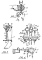
- Figures 1-4 Illustrate a preliminary preparation of the patient's distal tibia as part of the method of the present invention.
- the patient's tibia 10 is shown as is the proximal tibia 11.
- a drill 13 is used to track the patient's intramedullary canal 12 for receiving a reamer 21.
- the patient's femur 14 that has already been surgically prepared to receive a trial femoral prosthesis.
- the distal femur 15 is typically prepared with anterior and posterior cuts that are parallel to each other, a distal cut that is generally perpendicular to the anterior and posterior cuts, and diagonally extending chamfer cuts that extend between the distal cut and the respective posterior and anterior cuts.
- an ankle damp 16 has been installed at the patient's ankle 17 and with an alignment sleeve 18 that is positioned generally parallel to the patient's tibia.
- the sleeve 18 provides a coupling 19 for forming a connection with the bottom of tibial cutting guide 20 of the present invention.
- Ankle clamps 16 are commercially available and can be seen for example in the Steele patent 5,197,944, incorporated herein by reference.
- the tibial cutting guide 20 can be seen placed adjacent the patients proximal tibia 11.
- the tibial cutting guide 20 can be seen attached to the tibial stylus 50, and the assembly of cutting guide 20 and stylus 50 being attached to reamer 21 mounted in the patients intramedullary canal.
- Stylus 50 is shown more particularly in Figures 5-12.
- Cutting guide 20 is shown more particularly in Figures 13-16.
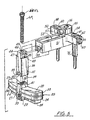
- Cutting guide 20 includes a block body 22 that includes a pair of upper flanges 23 and a pair of lower flanges 24. Slots 25,26 extend between the upper flanges 23 and the lower flanges 24. The slots 25, 26 provide a guide for a flat cutting blade such as the cutting blade 73 shown in Figure 4 which can be a commercially available powered saw. The saw blade 73 cuts through the patient's proximal tibia 11 as shown in Figure 4 along a line 74 that is generally perpendicular to the patient's intramedullary canal. In Figure 4, the block 22 has been attached to the proximal tibia 11 using a plurality of bone spikes 30.
- Tibial cutting guide 20 further provides a center portion 27 that can be used to attach the cutting block body 22 to the tibial stylus 50 and to ankle clamp 16 at coupling 19.
- Cutting block body 22 provides a lower attachment portion 28 having a plurality of cylindrical bores 29 therethrough as shown in Figures 13 and 14. These cylindrical openings 29 provide a cylindrical shape that corresponds generally to the outer configuration of a bone spike 30.
- One or more bone spikes can be placed through a corresponding plurality of the openings 29 for affixing the block body 22 to the patient's proximal tibia after alignment has been accomplished using elongated reamer rod 21 placed in the patient's intramedullary canal 12, the stylus 50, and ankle clamp 16.
- Vertical rod 31 extends from coupling 19 to center portion 27 of tibial cutting block body 22.
- a set screw 32 threadably engages opening 33 of central portion 27 of cutting block body 22.
- Cylindrical socket 34 receives the upper and of vertical rod 31. The set screw 32 can be tightened against the rod as it occupies the cylindrical socket 34.
- An upper cylindrically-shaped internally threaded opening 35 allows the cutting block body 22 to be attached to tibial stylus 50.
- Vertical post 36 extends between stylus 50 and cutting block body 22.
- the post 36 has a central longitudinal axis that is perpendicular to the plane defined by slots 25, 26. Further. the central longitudinal axis of post 36 is parallel to the central longitudinal axis of reamer rod 21 that is mounted in the patient's intramedullarycanal.
- the post 38 has a lower end 37 with a pair of flanges 38, 39 having a recess 40 therebetween.
- An upwardly projecting portion 41 of the center portion 27 of cutting block body 22 registers in the recess 40. Further. the flanges 38, 39 closely conform to the projecting portion 41 upon assembly.
- a threaded connection can be used to form a connection between the threaded opening 35 and bolt 49 that extends through vertical bore 46 of vertical post 36.
- a bolted connection can be used to assemble the vertical post 36 to the cutting block body 22, for example.
- the upper end 43 of post 36 has a transverse cross section that corresponds in size and shape to the transverse cross section of the longitudinally extending slot 53.
- Slot 53 extends through horizontal beam 51 of tibial stylus 50.
- the slot 53 communicates with a longitudinal opening 52 in the upper surface of the horizontal beam 51.
- a transverse probe holder 54 extends at generally right angles to the beam 51.
- a bushing 55 extends upwardly from the connection between beam 51 and probe holder 54.
- the bushing 55 provides a vertical open ended bore 56 that receives reamer 21.
- Set screw 57 can be used to tighten bushing 55 and the entire tibial stylus 50 to reamer 21.
- Internally threaded opening 70 receives the set screw 57.
- Probe holder 54 includes a pair of sides 58, 59 each having an elongated vertically extending probes 60, 61 respectively.
- the probe holder 54 has an upper generalty flat surface 62 that is perpendicular to the central longitudinal axis of bore 56 and to the central longitudinal axis reamer rod 21.
- Each probe 60, 61 moves vertically in an opening 66, 67 respectively.
- a pair of horizontal openings 88, 69 carry detent locking members 63, 64 respectively.
- the detent locking members 63, 64 can be spring loaded with springs 97, 98.
- Each of the detent locking members 63, 64 have openings that allow the probes 60, 61 to pass therethrough.
- Each probe 60, 61 provides a plurality of vertically spaced teeth 76 thereon (see Figure 6). Spaces between the teeth 76 are engaged by the respective detent locking member 63, 64 at stop 95 when they are released, thereby affixing the position of each of the probes 60,61 relative to the probe holder 54.
- a stop pin 101 holds each detent locking member 63,64 in its opening 68, 89.
- Longitudinal opening 52 is surrounded by side walls 72 and by longitudinally extending shoulders 71. This allows the placement of a bolt 49 into slot 52 and through the center of vertical bore 46 of vertical post 36 for attaching to threaded opening 35. Further, the head 43 of the bolt 49 rests on the shoulder 71 transferring load thereto.
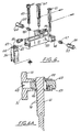
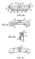
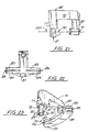
- tibial secondary prep guide 75 has an instrument body 76 that includes a pair of spaced apart vertical posts including the post 77 and the post 82.
- Post 77 carries a cylindrical cutting element 78 with a plurality of circumferentially spaced and radially extending cutting blades 79-81.
- the post 82 supports a pair of flanged portions including upper flanges 83 and lower flanges 84.
- a pair of flat cutting blade guide slots 85, 85 are positioned between the upper flanges and the lower flanges 83, as shown in Figures 21-23.
- the surgeon places the tibial secondary prep guide over the rod 21 that is installed in the patient's intramedullary canal. This registers the three cutting blades 79-81 and the cylindrical cutting element 78 at the center of the patients proximal tibia 11, as shown in Figure 17.
- the surgeon hammers the flat side 88 of lnstrument body 76 driving the cutting blades 79-81 into the proximal tibia 11 as shown in Figures 17-18.
- the surgeon hammers the surface 88 until the blades 79-81 are just beneath the surface of Proximal tibia 11 as shown in Figure 18. This allows the surgeon to shave a layer of tissue from proximal tibia 11 with great precision.
- the saw blade 89 is supported not only by the flanges 83, 84, but also by the upper surfaces 90 of blades 79-81 which are in a common plane with the upper surface 91 of the flange 84, as shown in Figure 31.
- the dotted line 102 in Figure 21 shows the path taken by saw blade 89 to secondarily cut the proximal tibia
- a trial prosthesis can be installed on the patient's distal tibia 11.
- a tibial trial prosthesis 92 is shown as installed into the patient's intramedullary canal 12.
- the tibial trial prosthesis 92 can include three components, a metallic plate or tray 93, a stem or plug 94, and a plastic trial insert 95.
- a tibial prosthesis 92 has been installed by the surgeon on the patient's proximal tibial 11.
- the surgeon has also installed a trial femoral prosthesis 100 on the distal femur 15.
- tibia 11 proximal tibia 12 intramedullary canal 13 drill 14 femur 15 distal femur 16 ankle clamp 17 ankle 18 alignment sleeve 19 coupling 20 tibial cutting guide 21 elongated reamer rod 22 cutting block body 23 upper flange 24 lower flange 25 horizontal slot 26 horizontal slot 27 center portion 28 attachment portion 29 cylindrical bores 30 bone spikes 31 vertical rod 32 set screw 33 intemally threaded opening 34 cylindrical socket 35 internally threaded opening 36 vertical post 37 lower end 38 flange 39 flange 40 recess 41 projecting portion 43 head 44 shoulder 45 shoulder 46 vertical bore 47 recess 48 recess 49 bolt 50 tibial stylus 51 horizontal beam 52 longitudinal opening 53 longitudinal opening 54 probe holder 55 bushing 56 vertical open ended bore 57 set screw 58 side 59 side 60 probe 61 probe 62 flat surface 63 detent locking member 64 detent locking member
Landscapes
- Health & Medical Sciences (AREA)
- Surgery (AREA)
- Life Sciences & Earth Sciences (AREA)
- Medical Informatics (AREA)
- Animal Behavior & Ethology (AREA)
- Veterinary Medicine (AREA)
- Nuclear Medicine, Radiotherapy & Molecular Imaging (AREA)
- Public Health (AREA)
- General Health & Medical Sciences (AREA)
- Engineering & Computer Science (AREA)
- Biomedical Technology (AREA)
- Heart & Thoracic Surgery (AREA)
- Molecular Biology (AREA)
- Orthopedic Medicine & Surgery (AREA)
- Dentistry (AREA)
- Physical Education & Sports Medicine (AREA)
- Transplantation (AREA)
- Oral & Maxillofacial Surgery (AREA)
- Surgical Instruments (AREA)
- Prostheses (AREA)
- Paper (AREA)
- Fittings On The Vehicle Exterior For Carrying Loads, And Devices For Holding Or Mounting Articles (AREA)
- Stringed Musical Instruments (AREA)
- Materials For Medical Uses (AREA)
Priority Applications (1)
| Application Number | Priority Date | Filing Date | Title |
|---|---|---|---|
| EP03004674.2A EP1323386B1 (en) | 1995-02-15 | 1996-02-15 | Tibial resection instrument |
Applications Claiming Priority (3)
| Application Number | Priority Date | Filing Date | Title |
|---|---|---|---|
| US08/388,983 US5578039A (en) | 1995-02-15 | 1995-02-15 | Tibial resection instrumentation and surgical method |
| US388983 | 1995-02-15 | ||
| PCT/US1996/002061 WO1996025106A1 (en) | 1995-02-15 | 1996-02-15 | Tibial resection instrument |
Related Child Applications (1)
| Application Number | Title | Priority Date | Filing Date |
|---|---|---|---|
| EP03004674.2A Division EP1323386B1 (en) | 1995-02-15 | 1996-02-15 | Tibial resection instrument |
Publications (3)
| Publication Number | Publication Date |
|---|---|
| EP0809468A1 EP0809468A1 (en) | 1997-12-03 |
| EP0809468A4 EP0809468A4 (en) | 1998-04-01 |
| EP0809468B1 true EP0809468B1 (en) | 2003-11-19 |
Family
ID=23536361
Family Applications (2)
| Application Number | Title | Priority Date | Filing Date |
|---|---|---|---|
| EP96906459A Expired - Lifetime EP0809468B1 (en) | 1995-02-15 | 1996-02-15 | Tibial resection instrument |
| EP03004674.2A Expired - Lifetime EP1323386B1 (en) | 1995-02-15 | 1996-02-15 | Tibial resection instrument |
Family Applications After (1)
| Application Number | Title | Priority Date | Filing Date |
|---|---|---|---|
| EP03004674.2A Expired - Lifetime EP1323386B1 (en) | 1995-02-15 | 1996-02-15 | Tibial resection instrument |
Country Status (13)
| Country | Link |
|---|---|
| US (3) | US5578039A (ja) |
| EP (2) | EP0809468B1 (ja) |
| JP (2) | JP3804975B2 (ja) |
| KR (2) | KR100430362B1 (ja) |
| CN (1) | CN1175893A (ja) |
| AT (1) | ATE254430T1 (ja) |
| AU (1) | AU693665B2 (ja) |
| CA (1) | CA2211032A1 (ja) |
| DE (1) | DE69630776T2 (ja) |
| DK (1) | DK0809468T3 (ja) |
| ES (1) | ES2211947T3 (ja) |
| PT (1) | PT809468E (ja) |
| WO (1) | WO1996025106A1 (ja) |
Families Citing this family (135)
| Publication number | Priority date | Publication date | Assignee | Title |
|---|---|---|---|---|
| US8603095B2 (en) | 1994-09-02 | 2013-12-10 | Puget Bio Ventures LLC | Apparatuses for femoral and tibial resection |
| US6695848B2 (en) * | 1994-09-02 | 2004-02-24 | Hudson Surgical Design, Inc. | Methods for femoral and tibial resection |
| US6077270A (en) * | 1995-05-31 | 2000-06-20 | Katz; Lawrence | Method and apparatus for locating bone cuts at the distal condylar femur region to receive a femoral prothesis and to coordinate tibial and patellar resection and replacement with femoral resection and replacement |
| US6024746A (en) * | 1995-05-31 | 2000-02-15 | Lawrence Katz | Method and apparatus for locating bone cuts at the distal condylar femur region to receive a femoral prothesis and to coordinate tibial and patellar resection and replacement with femoral resection and replacement |
| US5916219A (en) * | 1997-02-10 | 1999-06-29 | Matsuno; Shigeo | Tibial plateau resection guide |
| US6090114A (en) * | 1997-02-10 | 2000-07-18 | Stryker Howmedica Osteonics Corp. | Tibial plateau resection guide |
| US5779709A (en) * | 1997-02-12 | 1998-07-14 | Wright Medical Technology, Inc. | Ulnar cut guide alignment system |
| GB2322304B (en) * | 1997-02-21 | 2001-03-14 | Biomet Ltd | Surgical Tool Aligning Device |
| US5976147A (en) * | 1997-07-11 | 1999-11-02 | Johnson & Johnson Professional, Inc | Modular instrumentation for bone preparation and implant trial reduction of orthopedic implants |
| WO1999040864A1 (en) * | 1998-02-12 | 1999-08-19 | Midwest Orthopaedic Research Foundation | Tibial resection guide |
| US6063091A (en) * | 1998-10-13 | 2000-05-16 | Stryker Technologies Corporation | Methods and tools for tibial intermedullary revision surgery and associated tibial components |
| US6221035B1 (en) * | 1998-11-16 | 2001-04-24 | Richard J. Kana | Automatic ankle clamp |
| US6277123B1 (en) | 1999-09-10 | 2001-08-21 | Depuy Orthopaedics, Inc. | Prosthesis positioning apparatus and method for implanting a prosthesis |
| US6059831A (en) * | 1999-03-31 | 2000-05-09 | Biomet, Inc. | Method of implanting a uni-condylar knee prosthesis |
| FR2791549B1 (fr) * | 1999-04-01 | 2001-05-25 | Aesculap Sa | Dispositif de positionnement d'une extremite proximale d'un tibia par rapport a un guide de coupe, comportant une poignee de reglage |
| US7104996B2 (en) * | 2000-01-14 | 2006-09-12 | Marctec. Llc | Method of performing surgery |
| US7635390B1 (en) | 2000-01-14 | 2009-12-22 | Marctec, Llc | Joint replacement component having a modular articulating surface |
| US6702821B2 (en) | 2000-01-14 | 2004-03-09 | The Bonutti 2003 Trust A | Instrumentation for minimally invasive joint replacement and methods for using same |
| US6712856B1 (en) * | 2000-03-17 | 2004-03-30 | Kinamed, Inc. | Custom replacement device for resurfacing a femur and method of making the same |
| DE20014377U1 (de) * | 2000-08-19 | 2002-01-10 | Stratec Medical Ag Oberdorf | Vorrichtung zur Optimierung einer Knie-Endoprothese |
| US8062377B2 (en) | 2001-03-05 | 2011-11-22 | Hudson Surgical Design, Inc. | Methods and apparatus for knee arthroplasty |
| US6723102B2 (en) | 2001-06-14 | 2004-04-20 | Alexandria Research Technologies, Llc | Apparatus and method for minimally invasive total joint replacement |
| US6482209B1 (en) | 2001-06-14 | 2002-11-19 | Gerard A. Engh | Apparatus and method for sculpting the surface of a joint |
| KR20030002219A (ko) * | 2001-06-30 | 2003-01-08 | 한국과학기술원 | 고관절수술로봇을 위한 대퇴골 고정식 로봇설치대 |
| FR2826860B1 (fr) * | 2001-07-09 | 2004-03-05 | Tornier Sa | Ancillaire de pose d'un composant cubital et/ou d'un composant radial de prothese de coude |
| GB0119540D0 (en) * | 2001-08-10 | 2001-10-03 | Depuy Int Ltd | Tibial resection guide |
| US7708741B1 (en) | 2001-08-28 | 2010-05-04 | Marctec, Llc | Method of preparing bones for knee replacement surgery |
| AUPR865701A0 (en) * | 2001-11-02 | 2001-11-29 | Egan, Michael | Surgical apparatus and surgical methods |
| US6712823B2 (en) * | 2001-12-14 | 2004-03-30 | Wright Medical Technology Inc. | Humeral head resection guide |
| AU2003205311A1 (en) * | 2002-01-25 | 2003-09-02 | Depuy Products, Inc. | Extramedullary fluoroscopic alignment guide |
| AU2002951548A0 (en) * | 2002-09-19 | 2002-10-03 | Flinders Technologies Pty. Ltd. | Implant clamp and method |
| EP1555963A4 (en) | 2002-10-23 | 2008-12-31 | Mako Surgical Corp | MODULAR FEMORAL ELEMENT FOR REPLACING THE WHOLE KNEE JOINT BY MINIMALLY INVASIVE IMPLANTATION |
| US7326252B2 (en) | 2002-12-20 | 2008-02-05 | Smith & Nephew, Inc. | High performance knee prostheses |
| US7887542B2 (en) | 2003-01-15 | 2011-02-15 | Biomet Manufacturing Corp. | Method and apparatus for less invasive knee resection |
| US7789885B2 (en) | 2003-01-15 | 2010-09-07 | Biomet Manufacturing Corp. | Instrumentation for knee resection |
| US7837690B2 (en) | 2003-01-15 | 2010-11-23 | Biomet Manufacturing Corp. | Method and apparatus for less invasive knee resection |
| US8551100B2 (en) | 2003-01-15 | 2013-10-08 | Biomet Manufacturing, Llc | Instrumentation for knee resection |
| US20040153066A1 (en) | 2003-02-03 | 2004-08-05 | Coon Thomas M. | Apparatus for knee surgery and method of use |
| US7238190B2 (en) * | 2003-03-28 | 2007-07-03 | Concepts In Medicine Iii, Llc | Surgical apparatus to allow replacement of degenerative ankle tissue |
| US7488324B1 (en) | 2003-12-08 | 2009-02-10 | Biomet Manufacturing Corporation | Femoral guide for implanting a femoral knee prosthesis |
| US20060030854A1 (en) | 2004-02-02 | 2006-02-09 | Haines Timothy G | Methods and apparatus for wireplasty bone resection |
| US8114083B2 (en) | 2004-01-14 | 2012-02-14 | Hudson Surgical Design, Inc. | Methods and apparatus for improved drilling and milling tools for resection |
| US7815645B2 (en) | 2004-01-14 | 2010-10-19 | Hudson Surgical Design, Inc. | Methods and apparatus for pinplasty bone resection |
| US9814539B2 (en) | 2004-01-14 | 2017-11-14 | Puget Bioventures Llc | Methods and apparatus for conformable prosthetic implants |
| US8021368B2 (en) | 2004-01-14 | 2011-09-20 | Hudson Surgical Design, Inc. | Methods and apparatus for improved cutting tools for resection |
| US7857814B2 (en) | 2004-01-14 | 2010-12-28 | Hudson Surgical Design, Inc. | Methods and apparatus for minimally invasive arthroplasty |
| US7993341B2 (en) | 2004-03-08 | 2011-08-09 | Zimmer Technology, Inc. | Navigated orthopaedic guide and method |
| US8114086B2 (en) | 2004-03-08 | 2012-02-14 | Zimmer Technology, Inc. | Navigated cut guide locator |
| GB0405386D0 (en) * | 2004-03-10 | 2004-04-21 | Depuy Int Ltd | Device |
| US7806898B2 (en) * | 2004-07-09 | 2010-10-05 | Zimmer, Inc. | Modular guide systems and related rasps and methods for resecting a joint articulation surface |
| US8157867B2 (en) | 2004-07-09 | 2012-04-17 | Zimmer, Inc. | Trochlear groove implants and related methods and instruments |
| US20060064104A1 (en) * | 2004-09-09 | 2006-03-23 | Kana Richard J | Translating surgical mount |
| US7776044B2 (en) * | 2004-12-21 | 2010-08-17 | Zimmer Technology, Inc. | Tibial tray inserter |
| US20060155293A1 (en) * | 2005-01-07 | 2006-07-13 | Zimmer Technology | External rotation cut guide |
| US7618420B2 (en) * | 2005-02-17 | 2009-11-17 | Howmedica Osteonics Corp. | Locking intramedullary jig |
| US8979853B2 (en) * | 2005-02-17 | 2015-03-17 | Lucas Anissian | Method and system for determining resection guidelines for joint replacement surgical procedures |
| US7344542B2 (en) * | 2005-02-18 | 2008-03-18 | Howmedica Osteonics Corp. | Pin extraction assembly |
| US7695479B1 (en) | 2005-04-12 | 2010-04-13 | Biomet Manufacturing Corp. | Femoral sizer |
| US7601154B2 (en) * | 2005-04-18 | 2009-10-13 | Uni-Knee, Llc | Unicondylar knee instrument system |
| US7618422B2 (en) * | 2005-11-07 | 2009-11-17 | Howmedica Osteonics Corp. | Tibial augmentation guide |
| US9241800B2 (en) * | 2005-12-21 | 2016-01-26 | Orthopaedic International Inc. | Tibial component with a conversion module for a knee implant |
| US7744600B2 (en) | 2006-01-10 | 2010-06-29 | Zimmer Technology, Inc. | Bone resection guide and method |
| US9339278B2 (en) | 2006-02-27 | 2016-05-17 | Biomet Manufacturing, Llc | Patient-specific acetabular guides and associated instruments |
| US8407067B2 (en) | 2007-04-17 | 2013-03-26 | Biomet Manufacturing Corp. | Method and apparatus for manufacturing an implant |
| US10278711B2 (en) | 2006-02-27 | 2019-05-07 | Biomet Manufacturing, Llc | Patient-specific femoral guide |
| US7780672B2 (en) | 2006-02-27 | 2010-08-24 | Biomet Manufacturing Corp. | Femoral adjustment device and associated method |
| US8603180B2 (en) | 2006-02-27 | 2013-12-10 | Biomet Manufacturing, Llc | Patient-specific acetabular alignment guides |
| US9173661B2 (en) | 2006-02-27 | 2015-11-03 | Biomet Manufacturing, Llc | Patient specific alignment guide with cutting surface and laser indicator |
| US9345548B2 (en) | 2006-02-27 | 2016-05-24 | Biomet Manufacturing, Llc | Patient-specific pre-operative planning |
| US20150335438A1 (en) | 2006-02-27 | 2015-11-26 | Biomet Manufacturing, Llc. | Patient-specific augments |
| US9907659B2 (en) | 2007-04-17 | 2018-03-06 | Biomet Manufacturing, Llc | Method and apparatus for manufacturing an implant |
| US8591516B2 (en) | 2006-02-27 | 2013-11-26 | Biomet Manufacturing, Llc | Patient-specific orthopedic instruments |
| US9113971B2 (en) | 2006-02-27 | 2015-08-25 | Biomet Manufacturing, Llc | Femoral acetabular impingement guide |
| US9289253B2 (en) | 2006-02-27 | 2016-03-22 | Biomet Manufacturing, Llc | Patient-specific shoulder guide |
| US8070752B2 (en) | 2006-02-27 | 2011-12-06 | Biomet Manufacturing Corp. | Patient specific alignment guide and inter-operative adjustment |
| US9918740B2 (en) | 2006-02-27 | 2018-03-20 | Biomet Manufacturing, Llc | Backup surgical instrument system and method |
| US7695520B2 (en) | 2006-05-31 | 2010-04-13 | Biomet Manufacturing Corp. | Prosthesis and implementation system |
| US9795399B2 (en) | 2006-06-09 | 2017-10-24 | Biomet Manufacturing, Llc | Patient-specific knee alignment guide and associated method |
| WO2008091358A1 (en) * | 2006-06-12 | 2008-07-31 | Smith And Nephew Inc | Systems, methods and devices for tibial resection |
| US8372078B2 (en) | 2006-06-30 | 2013-02-12 | Howmedica Osteonics Corp. | Method for performing a high tibial osteotomy |
| ES2568932T3 (es) | 2006-06-30 | 2016-05-05 | Smith & Nephew, Inc. | Prótesis articulada para movimiento anatómico |
| US20080097451A1 (en) * | 2006-09-20 | 2008-04-24 | United Orthopedic Corporation | Surgical tool assembly for total knee arthroplasty |
| GB2445620B (en) * | 2007-01-13 | 2011-10-26 | Derek James Wallace Mcminn | Instrumentation for knee surgery |
| US7959637B2 (en) | 2007-03-13 | 2011-06-14 | Biomet Manufacturing Corp. | Distal femoral cutting guide |
| GB0718417D0 (en) * | 2007-09-21 | 2007-10-31 | Depuy Int Ltd | Intramedullary rod instrument |
| GB0718418D0 (en) * | 2007-09-21 | 2007-10-31 | Depuy Int Ltd | Adjustable surgical instrument |
| US8265949B2 (en) | 2007-09-27 | 2012-09-11 | Depuy Products, Inc. | Customized patient surgical plan |
| CN102652686A (zh) | 2007-09-30 | 2012-09-05 | 德普伊产品公司 | 定制的患者专用整形外科手术器械 |
| US8357111B2 (en) | 2007-09-30 | 2013-01-22 | Depuy Products, Inc. | Method and system for designing patient-specific orthopaedic surgical instruments |
| US8337498B2 (en) * | 2008-08-13 | 2012-12-25 | Rasmussen G Lynn | Systems and methods for providing a bone milling device |
| US8740911B2 (en) * | 2008-11-07 | 2014-06-03 | Howmedica Osteonics Corp. | Method of preparing a femur for implantation of a femoral implant |
| US8808303B2 (en) * | 2009-02-24 | 2014-08-19 | Microport Orthopedics Holdings Inc. | Orthopedic surgical guide |
| GB0909121D0 (en) * | 2009-05-28 | 2009-07-01 | Depuy Int Ltd | Bone cutting assembly |
| BRPI1011426A2 (pt) * | 2009-05-29 | 2016-03-15 | Brian W Mc Kinnon | métodos e aparelho para executar artroplastia de joelho |
| AU2011220884A1 (en) * | 2010-02-25 | 2012-09-13 | Depuy Products, Inc. | Customized patient-specific tibial cutting blocks |
| RU2013109815A (ru) | 2010-08-12 | 2014-09-20 | Смит Энд Нефью, Инк. | Конструкция, используемая для крепления ортопедического имплантата, и способ его установки на кости |
| US9492183B2 (en) * | 2010-10-14 | 2016-11-15 | Smith & Nephew, Inc. | Patient-matched instrumentation and methods |
| GB201019490D0 (en) | 2010-11-18 | 2010-12-29 | Depuy Ireland | Angular adjustment mechanism, surgical alignment guide and surgical instrument assembly |
| GB201019491D0 (en) * | 2010-11-18 | 2010-12-29 | Depuy Ireland | Surgical cutting guide, surgical alignment guide and surgical instrument system |
| US9968376B2 (en) | 2010-11-29 | 2018-05-15 | Biomet Manufacturing, Llc | Patient-specific orthopedic instruments |
| US9241745B2 (en) | 2011-03-07 | 2016-01-26 | Biomet Manufacturing, Llc | Patient-specific femoral version guide |
| US8979847B2 (en) | 2011-06-06 | 2015-03-17 | Biomet Manufacturing, Llc | Method and apparatus for implanting a knee prosthesis |
| WO2013063375A1 (en) | 2011-10-27 | 2013-05-02 | Smith & Nephew, Inc. | Devices and methods for performing knee arthroplasty |
| US8858559B2 (en) | 2012-02-06 | 2014-10-14 | Medtronic Ps Medical, Inc. | Saw blade stability and collet system mechanism |
| US8936597B2 (en) | 2012-02-06 | 2015-01-20 | Medtronic Ps Medical, Inc. | Deflectable finger connection feature on surgical saw blade |
| KR101273262B1 (ko) * | 2012-03-09 | 2013-06-11 | (주)티디엠 | 경골 절단 가이드 및 이를 구비하는 경골 절단 가이드 세트 |
| US10499933B2 (en) | 2012-10-18 | 2019-12-10 | Smith & Nephew, Inc. | Alignment devices and methods |
| US8740985B1 (en) | 2012-11-30 | 2014-06-03 | Smith & Nephew, Inc. | Knee prosthesis |
| US9480571B2 (en) | 2012-12-27 | 2016-11-01 | Wright Medical Technology, Inc. | Ankle replacement system and method |
| US9974588B2 (en) | 2012-12-27 | 2018-05-22 | Wright Medical Technology, Inc. | Ankle replacement system and method |
| US10080573B2 (en) | 2012-12-27 | 2018-09-25 | Wright Medical Technology, Inc. | Ankle replacement system and method |
| US9918724B2 (en) | 2012-12-27 | 2018-03-20 | Wright Medical Technology, Inc. | Ankle replacement system and method |
| CA2836651C (en) | 2012-12-27 | 2016-03-22 | Wright Medical Technology, Inc. | Ankle replacement system and method |
| CA3125595A1 (en) * | 2013-03-14 | 2014-09-25 | Wright Medical Technology, Inc. | Ankle replacement system and method |
| CN104095664B (zh) | 2013-04-12 | 2016-12-28 | 德普伊(爱尔兰)公司 | 股骨远端夹具组件和具有该组件的股骨远端切割器械 |
| WO2016100526A1 (en) * | 2014-12-17 | 2016-06-23 | Hartford James Matthew | A guide for re-cutting tibial resections for total knee replacement |
| CA3101901A1 (en) | 2016-03-23 | 2017-09-28 | Wright Medical Technology, Inc. | Fixation apparatus and method for total ankle replacement |
| KR101779920B1 (ko) * | 2016-03-29 | 2017-09-21 | 주식회사 코렌텍 | 경골절삭가이드 결합 어셈블리 |
| US10456142B2 (en) | 2016-06-03 | 2019-10-29 | Mako Surgical Corp. | Surgical saw and saw blade for use therewith |
| CN106037924B (zh) * | 2016-07-08 | 2018-09-07 | 上海市杨浦区中心医院 | 胫骨结节牵引钉置入导向器 |
| CN106388899B (zh) * | 2016-10-16 | 2019-01-04 | 北京工业大学 | 一套3d打印制造的股骨远端肿瘤精准切除手术辅助器械系统 |
| US10722310B2 (en) | 2017-03-13 | 2020-07-28 | Zimmer Biomet CMF and Thoracic, LLC | Virtual surgery planning system and method |
| IT201700036225A1 (it) * | 2017-04-03 | 2018-10-03 | Limacorporate Spa | Strumento chirurgico ortopedico per posizionare una guida di taglio tibiale |
| US10687824B2 (en) | 2017-07-21 | 2020-06-23 | Stryker European Holdings I, Llc | Surgical saw and saw blade for use therewith |
| US10835262B2 (en) * | 2017-12-06 | 2020-11-17 | Howmedica Osteonics Corp. | Tibial posterior slope alignment guide |
| US11246603B2 (en) * | 2018-01-26 | 2022-02-15 | Microport Orthopedics, Inc. | Dual stylus variable angle total knee instruments and methods |
| US11166663B2 (en) | 2018-05-25 | 2021-11-09 | MicroPort Orthopedics Inc. | Soft tissue tension and bone resection instruments and methods |
| US11051829B2 (en) | 2018-06-26 | 2021-07-06 | DePuy Synthes Products, Inc. | Customized patient-specific orthopaedic surgical instrument |
| DE102018130119A1 (de) * | 2018-11-28 | 2020-05-28 | Aesculap Ag | Fixierungssystem und Ausrichtungsvorrichtung |
| DE102018130117A1 (de) | 2018-11-28 | 2020-05-28 | Aesculap Ag | Fixierungsklammer und Ausrichtungsvorrichtung |
| DE102019104965A1 (de) * | 2019-02-27 | 2020-08-27 | Aesculap Ag | Fixierungsvorrichtung für ein Tibia-Ausrichtungssystem |
| FR3093418B1 (fr) * | 2019-03-04 | 2021-02-12 | Fh Orthopedics | Guide de coupe tibial pour réséquer un tibia d’un patient pour la pose d’une prothèse de genou |
| US20210361326A1 (en) | 2020-05-19 | 2021-11-25 | Shukla Medical | Dual rod implant cutter |
| US11872137B2 (en) | 2021-06-15 | 2024-01-16 | Wright Medical Technology, Inc. | Unicompartmental ankle prosthesis |
| AT526622A1 (de) * | 2022-10-28 | 2024-05-15 | Univ Graz Medizinische | Bohrlehre zum geführten Bohren eines Knochens |
Family Cites Families (15)
| Publication number | Priority date | Publication date | Assignee | Title |
|---|---|---|---|---|
| US4016606A (en) * | 1975-07-14 | 1977-04-12 | Research Corporation | Knee joint prosthesis |
| US4601289A (en) * | 1985-04-02 | 1986-07-22 | Dow Corning Wright | Femoral trial prosthesis/rasp assembly |
| US4952213A (en) * | 1989-02-03 | 1990-08-28 | Boehringer Mannheim Corporation | Tibial cutting guide |
| US4938769A (en) * | 1989-05-31 | 1990-07-03 | Shaw James A | Modular tibial prosthesis |
| US5171244A (en) * | 1990-01-08 | 1992-12-15 | Caspari Richard B | Methods and apparatus for arthroscopic prosthetic knee replacement |
| GB9005496D0 (en) * | 1990-03-12 | 1990-05-09 | Howmedica | Tibial component for a replacement knee prosthesis and total knee prosthesis incorporating such a component |
| JPH03267055A (ja) * | 1990-03-16 | 1991-11-27 | Koshino Nariko | 人工膝関節の脛骨側コンポーネント |
| IT1248971B (it) * | 1990-06-22 | 1995-02-11 | Cremascoli G Srl | Apparecchiatura atta a consentire l'esecuzione di una corretta resezione femorale e tibiale per l'applicazione di protesi sostitutive dell'articolazione del ginocchio |
| FR2671714A1 (fr) * | 1991-01-17 | 1992-07-24 | Jeanson Jean Francois | Guide de coupe tibiale. |
| US5100408A (en) * | 1991-03-07 | 1992-03-31 | Smith & Nephew Richards Inc. | Femoral instrumentation for long stem surgery |
| US5514143A (en) * | 1991-11-27 | 1996-05-07 | Apogee Medical Products, Inc. | Apparatus and method for use during surgery |
| GB9202561D0 (en) * | 1992-02-07 | 1992-03-25 | Howmedica | Orthopaedic instrument |
| US5246459A (en) * | 1992-02-24 | 1993-09-21 | Elias Sarmed G | Modular tibial support pegs for the tibial component of a prosthetic knee replacement system |
| US5445642A (en) * | 1992-09-01 | 1995-08-29 | Depuy Inc. | Method for installing a femoral component |
| US5486178A (en) * | 1994-02-16 | 1996-01-23 | Hodge; W. Andrew | Femoral preparation instrumentation system and method |
-
1995
- 1995-02-15 US US08/388,983 patent/US5578039A/en not_active Expired - Lifetime
- 1995-06-07 US US08/480,845 patent/US5628749A/en not_active Expired - Lifetime
- 1995-06-07 US US08/484,611 patent/US5667511A/en not_active Expired - Lifetime
-
1996
- 1996-02-15 DE DE69630776T patent/DE69630776T2/de not_active Expired - Lifetime
- 1996-02-15 CA CA002211032A patent/CA2211032A1/en not_active Abandoned
- 1996-02-15 KR KR1019970705644A patent/KR100430362B1/ko not_active IP Right Cessation
- 1996-02-15 WO PCT/US1996/002061 patent/WO1996025106A1/en active IP Right Grant
- 1996-02-15 ES ES96906459T patent/ES2211947T3/es not_active Expired - Lifetime
- 1996-02-15 JP JP52514296A patent/JP3804975B2/ja not_active Expired - Fee Related
- 1996-02-15 PT PT96906459T patent/PT809468E/pt unknown
- 1996-02-15 EP EP96906459A patent/EP0809468B1/en not_active Expired - Lifetime
- 1996-02-15 DK DK96906459T patent/DK0809468T3/da active
- 1996-02-15 AT AT96906459T patent/ATE254430T1/de active
- 1996-02-15 AU AU49831/96A patent/AU693665B2/en not_active Ceased
- 1996-02-15 EP EP03004674.2A patent/EP1323386B1/en not_active Expired - Lifetime
- 1996-02-15 CN CN96191963A patent/CN1175893A/zh active Pending
-
2003
- 2003-03-26 KR KR1020030018686A patent/KR100431911B1/ko not_active IP Right Cessation
-
2005
- 2005-07-01 JP JP2005193954A patent/JP4610427B2/ja not_active Expired - Lifetime
Also Published As
| Publication number | Publication date |
|---|---|
| EP1323386A2 (en) | 2003-07-02 |
| US5578039A (en) | 1996-11-26 |
| KR100431911B1 (ko) | 2004-05-17 |
| DK0809468T3 (da) | 2004-03-29 |
| US5667511A (en) | 1997-09-16 |
| ATE254430T1 (de) | 2003-12-15 |
| EP1323386B1 (en) | 2013-06-26 |
| JP3804975B2 (ja) | 2006-08-02 |
| WO1996025106A1 (en) | 1996-08-22 |
| JPH11500035A (ja) | 1999-01-06 |
| JP2005324054A (ja) | 2005-11-24 |
| CN1175893A (zh) | 1998-03-11 |
| DE69630776D1 (de) | 2003-12-24 |
| DE69630776T2 (de) | 2004-09-23 |
| US5628749A (en) | 1997-05-13 |
| AU4983196A (en) | 1996-09-04 |
| KR19980702247A (ko) | 1998-07-15 |
| EP1323386A3 (en) | 2006-02-15 |
| EP0809468A1 (en) | 1997-12-03 |
| CA2211032A1 (en) | 1996-08-22 |
| KR100430362B1 (ko) | 2004-06-16 |
| ES2211947T3 (es) | 2004-07-16 |
| EP0809468A4 (en) | 1998-04-01 |
| JP4610427B2 (ja) | 2011-01-12 |
| AU693665B2 (en) | 1998-07-02 |
| PT809468E (pt) | 2004-04-30 |
Similar Documents
| Publication | Publication Date | Title |
|---|---|---|
| EP0809468B1 (en) | Tibial resection instrument | |
| AU689033B2 (en) | Tibial trial knee prosthesis and bone preparation system | |
| US6056754A (en) | Method and apparatus for patella resection and guide handle | |
| AU595265B2 (en) | Femoral surface shaping apparatus for posterior- stabilized knee implants | |
| US5702460A (en) | Revision femoral trial prosthesis | |
| US7967822B2 (en) | Methods and apparatus for orthopedic implants | |
| AU696251B2 (en) | Distal femoral cutting guide | |
| EP0378294B1 (en) | Femoral surface shaping guide for knee implants | |
| US6945976B2 (en) | Method and apparatus for resecting bone from an ulna in preparation for prosthetic implantation | |
| US5997543A (en) | Surgical instrumentation | |
| CA2090189C (en) | Knee prosthesis provisional apparatus and resection guide and method of use in knee replacement surgery | |
| US20120053591A1 (en) | Apparatuses for femoral and tibial resection | |
| WO1997029697A1 (en) | Distal femoral cutting block assembly | |
| AU729426B2 (en) | Tibial resection instrument | |
| AU750023B2 (en) | Tibial resection instrument | |
| IE83815B1 (en) | Surgical instrumentation |
Legal Events
| Date | Code | Title | Description |
|---|---|---|---|
| PUAI | Public reference made under article 153(3) epc to a published international application that has entered the european phase |
Free format text: ORIGINAL CODE: 0009012 |
|
| 17P | Request for examination filed |
Effective date: 19970722 |
|
| AK | Designated contracting states |
Kind code of ref document: A1 Designated state(s): AT BE CH DE DK ES FR GB GR IE IT LI LU MC NL PT SE |
|
| A4 | Supplementary search report drawn up and despatched |
Effective date: 19980211 |
|
| AK | Designated contracting states |
Kind code of ref document: A4 Designated state(s): AT BE CH DE DK ES FR GB GR IE IT LI LU MC NL PT SE |
|
| 17Q | First examination report despatched |
Effective date: 20020219 |
|
| GRAH | Despatch of communication of intention to grant a patent |
Free format text: ORIGINAL CODE: EPIDOS IGRA |
|
| GRAS | Grant fee paid |
Free format text: ORIGINAL CODE: EPIDOSNIGR3 |
|
| GRAA | (expected) grant |
Free format text: ORIGINAL CODE: 0009210 |
|
| AK | Designated contracting states |
Kind code of ref document: B1 Designated state(s): AT BE CH DE DK ES FR GB GR IE IT LI LU MC NL PT SE |
|
| REG | Reference to a national code |
Ref country code: GB Ref legal event code: FG4D |
|
| REG | Reference to a national code |
Ref country code: CH Ref legal event code: EP |
|
| REF | Corresponds to: |
Ref document number: 69630776 Country of ref document: DE Date of ref document: 20031224 Kind code of ref document: P |
|
| REG | Reference to a national code |
Ref country code: IE Ref legal event code: FG4D |
|
| PGFP | Annual fee paid to national office [announced via postgrant information from national office to epo] |
Ref country code: MC Payment date: 20040128 Year of fee payment: 9 |
|
| PGFP | Annual fee paid to national office [announced via postgrant information from national office to epo] |
Ref country code: SE Payment date: 20040204 Year of fee payment: 9 |
|
| PGFP | Annual fee paid to national office [announced via postgrant information from national office to epo] |
Ref country code: DK Payment date: 20040212 Year of fee payment: 9 |
|
| PG25 | Lapsed in a contracting state [announced via postgrant information from national office to epo] |
Ref country code: LU Free format text: LAPSE BECAUSE OF NON-PAYMENT OF DUE FEES Effective date: 20040215 |
|
| PG25 | Lapsed in a contracting state [announced via postgrant information from national office to epo] |
Ref country code: GR Free format text: LAPSE BECAUSE OF FAILURE TO SUBMIT A TRANSLATION OF THE DESCRIPTION OR TO PAY THE FEE WITHIN THE PRESCRIBED TIME-LIMIT Effective date: 20040219 |
|
| REG | Reference to a national code |
Ref country code: SE Ref legal event code: TRGR |
|
| PGFP | Annual fee paid to national office [announced via postgrant information from national office to epo] |
Ref country code: PT Payment date: 20040318 Year of fee payment: 9 |
|
| REG | Reference to a national code |
Ref country code: DK Ref legal event code: T3 |
|
| REG | Reference to a national code |
Ref country code: PT Ref legal event code: SC4A Free format text: AVAILABILITY OF NATIONAL TRANSLATION Effective date: 20040218 |
|
| REG | Reference to a national code |
Ref country code: ES Ref legal event code: FG2A Ref document number: 2211947 Country of ref document: ES Kind code of ref document: T3 |
|
| ET | Fr: translation filed | ||
| PLBE | No opposition filed within time limit |
Free format text: ORIGINAL CODE: 0009261 |
|
| STAA | Information on the status of an ep patent application or granted ep patent |
Free format text: STATUS: NO OPPOSITION FILED WITHIN TIME LIMIT |
|
| 26N | No opposition filed |
Effective date: 20040820 |
|
| PG25 | Lapsed in a contracting state [announced via postgrant information from national office to epo] |
Ref country code: SE Free format text: LAPSE BECAUSE OF NON-PAYMENT OF DUE FEES Effective date: 20050216 |
|
| PG25 | Lapsed in a contracting state [announced via postgrant information from national office to epo] |
Ref country code: MC Free format text: LAPSE BECAUSE OF NON-PAYMENT OF DUE FEES Effective date: 20050228 Ref country code: DK Free format text: LAPSE BECAUSE OF NON-PAYMENT OF DUE FEES Effective date: 20050228 |
|
| REG | Reference to a national code |
Ref country code: DK Ref legal event code: EBP |
|
| EUG | Se: european patent has lapsed | ||
| PG25 | Lapsed in a contracting state [announced via postgrant information from national office to epo] |
Ref country code: PT Free format text: LAPSE BECAUSE OF NON-PAYMENT OF DUE FEES Effective date: 20051116 |
|
| PG25 | Lapsed in a contracting state [announced via postgrant information from national office to epo] |
Ref country code: PT Free format text: LAPSE BECAUSE OF NON-PAYMENT OF DUE FEES Effective date: 20050215 |
|
| PGFP | Annual fee paid to national office [announced via postgrant information from national office to epo] |
Ref country code: IT Payment date: 20120213 Year of fee payment: 17 |
|
| PGFP | Annual fee paid to national office [announced via postgrant information from national office to epo] |
Ref country code: IE Payment date: 20130212 Year of fee payment: 18 Ref country code: ES Payment date: 20130215 Year of fee payment: 18 Ref country code: FR Payment date: 20130301 Year of fee payment: 18 Ref country code: DE Payment date: 20130213 Year of fee payment: 18 Ref country code: CH Payment date: 20130212 Year of fee payment: 18 Ref country code: GB Payment date: 20130213 Year of fee payment: 18 |
|
| PGFP | Annual fee paid to national office [announced via postgrant information from national office to epo] |
Ref country code: BE Payment date: 20130212 Year of fee payment: 18 Ref country code: NL Payment date: 20130209 Year of fee payment: 18 |
|
| PGFP | Annual fee paid to national office [announced via postgrant information from national office to epo] |
Ref country code: AT Payment date: 20130110 Year of fee payment: 18 |
|
| BERE | Be: lapsed |
Owner name: *SMITH & NEPHEW INC. Effective date: 20140228 |
|
| REG | Reference to a national code |
Ref country code: DE Ref legal event code: R119 Ref document number: 69630776 Country of ref document: DE |
|
| REG | Reference to a national code |
Ref country code: NL Ref legal event code: V1 Effective date: 20140901 |
|
| REG | Reference to a national code |
Ref country code: CH Ref legal event code: PL |
|
| REG | Reference to a national code |
Ref country code: AT Ref legal event code: MM01 Ref document number: 254430 Country of ref document: AT Kind code of ref document: T Effective date: 20140215 |
|
| GBPC | Gb: european patent ceased through non-payment of renewal fee |
Effective date: 20140215 |
|
| PG25 | Lapsed in a contracting state [announced via postgrant information from national office to epo] |
Ref country code: LI Free format text: LAPSE BECAUSE OF NON-PAYMENT OF DUE FEES Effective date: 20140228 Ref country code: NL Free format text: LAPSE BECAUSE OF NON-PAYMENT OF DUE FEES Effective date: 20140901 Ref country code: CH Free format text: LAPSE BECAUSE OF NON-PAYMENT OF DUE FEES Effective date: 20140228 |
|
| REG | Reference to a national code |
Ref country code: FR Ref legal event code: ST Effective date: 20141031 |
|
| REG | Reference to a national code |
Ref country code: DE Ref legal event code: R119 Ref document number: 69630776 Country of ref document: DE Effective date: 20140902 |
|
| PG25 | Lapsed in a contracting state [announced via postgrant information from national office to epo] |
Ref country code: AT Free format text: LAPSE BECAUSE OF NON-PAYMENT OF DUE FEES Effective date: 20140215 |
|
| REG | Reference to a national code |
Ref country code: IE Ref legal event code: MM4A |
|
| PG25 | Lapsed in a contracting state [announced via postgrant information from national office to epo] |
Ref country code: DE Free format text: LAPSE BECAUSE OF NON-PAYMENT OF DUE FEES Effective date: 20140902 Ref country code: BE Free format text: LAPSE BECAUSE OF NON-PAYMENT OF DUE FEES Effective date: 20140228 Ref country code: GB Free format text: LAPSE BECAUSE OF NON-PAYMENT OF DUE FEES Effective date: 20140215 Ref country code: IE Free format text: LAPSE BECAUSE OF NON-PAYMENT OF DUE FEES Effective date: 20140215 Ref country code: FR Free format text: LAPSE BECAUSE OF NON-PAYMENT OF DUE FEES Effective date: 20140228 |
|
| REG | Reference to a national code |
Ref country code: ES Ref legal event code: FD2A Effective date: 20150327 |
|
| PG25 | Lapsed in a contracting state [announced via postgrant information from national office to epo] |
Ref country code: ES Free format text: LAPSE BECAUSE OF NON-PAYMENT OF DUE FEES Effective date: 20140216 |
|
| PG25 | Lapsed in a contracting state [announced via postgrant information from national office to epo] |
Ref country code: IT Free format text: LAPSE BECAUSE OF NON-PAYMENT OF DUE FEES Effective date: 20140215 |