EP0809408A1 - Caméra à effets spéciaux - Google Patents
Caméra à effets spéciaux Download PDFInfo
- Publication number
- EP0809408A1 EP0809408A1 EP97401129A EP97401129A EP0809408A1 EP 0809408 A1 EP0809408 A1 EP 0809408A1 EP 97401129 A EP97401129 A EP 97401129A EP 97401129 A EP97401129 A EP 97401129A EP 0809408 A1 EP0809408 A1 EP 0809408A1
- Authority
- EP
- European Patent Office
- Prior art keywords
- signal
- video
- background
- camera
- subject
- Prior art date
- Legal status (The legal status is an assumption and is not a legal conclusion. Google has not performed a legal analysis and makes no representation as to the accuracy of the status listed.)
- Ceased
Links
- 230000000694 effects Effects 0.000 title description 2
- 238000012545 processing Methods 0.000 claims abstract description 42
- 230000003287 optical effect Effects 0.000 claims abstract description 10
- 230000006835 compression Effects 0.000 claims description 23
- 238000007906 compression Methods 0.000 claims description 23
- 230000033228 biological regulation Effects 0.000 claims description 15
- 230000005540 biological transmission Effects 0.000 claims description 14
- 238000012546 transfer Methods 0.000 claims description 8
- 238000001514 detection method Methods 0.000 claims description 7
- 238000000034 method Methods 0.000 claims description 7
- 230000008569 process Effects 0.000 claims description 6
- 238000005070 sampling Methods 0.000 claims description 6
- 230000007423 decrease Effects 0.000 claims description 4
- 230000001131 transforming effect Effects 0.000 claims description 4
- 230000001360 synchronised effect Effects 0.000 claims description 3
- 238000011144 upstream manufacturing Methods 0.000 claims description 3
- 230000009471 action Effects 0.000 claims description 2
- 238000000926 separation method Methods 0.000 abstract 2
- 238000010586 diagram Methods 0.000 description 10
- 230000006870 function Effects 0.000 description 8
- 230000006872 improvement Effects 0.000 description 7
- 241001080024 Telles Species 0.000 description 4
- 230000008901 benefit Effects 0.000 description 3
- 239000003086 colorant Substances 0.000 description 3
- 239000008186 active pharmaceutical agent Substances 0.000 description 2
- 238000004458 analytical method Methods 0.000 description 2
- 230000003247 decreasing effect Effects 0.000 description 2
- 230000009977 dual effect Effects 0.000 description 2
- 238000013139 quantization Methods 0.000 description 2
- 229920006395 saturated elastomer Polymers 0.000 description 2
- 230000007704 transition Effects 0.000 description 2
- XUIMIQQOPSSXEZ-UHFFFAOYSA-N Silicon Chemical compound [Si] XUIMIQQOPSSXEZ-UHFFFAOYSA-N 0.000 description 1
- 230000002238 attenuated effect Effects 0.000 description 1
- WHGYBXFWUBPSRW-FOUAGVGXSA-N beta-cyclodextrin Chemical compound OC[C@H]([C@H]([C@@H]([C@H]1O)O)O[C@H]2O[C@@H]([C@@H](O[C@H]3O[C@H](CO)[C@H]([C@@H]([C@H]3O)O)O[C@H]3O[C@H](CO)[C@H]([C@@H]([C@H]3O)O)O[C@H]3O[C@H](CO)[C@H]([C@@H]([C@H]3O)O)O[C@H]3O[C@H](CO)[C@H]([C@@H]([C@H]3O)O)O3)[C@H](O)[C@H]2O)CO)O[C@@H]1O[C@H]1[C@H](O)[C@@H](O)[C@@H]3O[C@@H]1CO WHGYBXFWUBPSRW-FOUAGVGXSA-N 0.000 description 1
- 230000015572 biosynthetic process Effects 0.000 description 1
- 238000004364 calculation method Methods 0.000 description 1
- 238000012937 correction Methods 0.000 description 1
- 238000005516 engineering process Methods 0.000 description 1
- 238000001914 filtration Methods 0.000 description 1
- 238000011002 quantification Methods 0.000 description 1
- 230000002441 reversible effect Effects 0.000 description 1
- 238000009738 saturating Methods 0.000 description 1
- 230000008054 signal transmission Effects 0.000 description 1
- 229910052710 silicon Inorganic materials 0.000 description 1
- 239000010703 silicon Substances 0.000 description 1
- 230000003595 spectral effect Effects 0.000 description 1
- 230000000007 visual effect Effects 0.000 description 1
Images


Classifications
-
- H—ELECTRICITY
- H04—ELECTRIC COMMUNICATION TECHNIQUE
- H04N—PICTORIAL COMMUNICATION, e.g. TELEVISION
- H04N9/00—Details of colour television systems
- H04N9/64—Circuits for processing colour signals
- H04N9/74—Circuits for processing colour signals for obtaining special effects
- H04N9/75—Chroma key
-
- H—ELECTRICITY
- H04—ELECTRIC COMMUNICATION TECHNIQUE
- H04N—PICTORIAL COMMUNICATION, e.g. TELEVISION
- H04N5/00—Details of television systems
- H04N5/222—Studio circuitry; Studio devices; Studio equipment
- H04N5/262—Studio circuits, e.g. for mixing, switching-over, change of character of image, other special effects ; Cameras specially adapted for the electronic generation of special effects
- H04N5/272—Means for inserting a foreground image in a background image, i.e. inlay, outlay
Definitions
- the present invention relates to the cutting of a subject moving in front of a background so as to be able to embed this subject on a new background.
- the cutting key allows the distinction between the background in front of which the subject evolves and the subject itself.
- the invention proposes a new definition of the cutting key and, consequently, a new device making it possible to obtain a cutting key according to this new definition.
- the invention relates to any type of electronic device using a new device such as that mentioned above.
- Calculating the key requires separating the color space into three zones: a first zone defining a volume representing the background, a second zone defining a volume representing the subject and a third zone defining a transition zone between the background and the topic.
- the first zone defining the volume representing the background is most often made up of a highly saturated blue color and having a very high apparent uniformity. It follows that the visible frequency band emitted by the background must be very narrow. This constraint of saturation and homogeneity of the background in front of which the subject evolves implies to light this background and, therefore the subject, with a lot of light. This significant lighting results in real nuisance with regard to visual realism and the quality of the images generated.
- the invention does not have this drawback.
- the invention relates to a camera for generating a video signal representing a subject moving in front of a background.
- the camera includes means for generating a subject cutting key signal from non-visible frequencies from the background.
- the cutting signal then comes directly from the camera.
- the invention also relates to a device making it possible to generate a signal for cutting a subject moving in front of a background.
- the device comprises means for generating a video signal representing the subject moving in front of the background and means for detecting the background using non-visible frequencies emitted by the background.
- the invention also relates to a system allowing the incrustation, on a second background, of a subject evolving in front of a first background.
- the system comprises a camera such as that according to the invention so as to generate a video signal representing the subject moving in front of the first background and a cutting key signal from non-visible frequencies originating from the first background, a device generating the signal video representing the second background, and a mixer making it possible to generate the image representing the subject embedded on the second background from the video signal representing the subject moving in front of the first background, from the cutting key signal, and from the video signal representing the second background.
- an advantage of the invention is that it allows the inlay of dimly lit subjects in visible light.
- Figure 1 shows the block diagram of a camera according to the invention.
- the camera 1 comprises a lens 2, an optical splitter 3, sensors 4, 5, 6, 7, processing circuits 8 and 9, a device 10 for multiplexing and modulation and a device 12 for modulation.
- the optical separator 3 which has the function of separating the beam which represents the subject and the background in front of which the subject evolves into four distinct beams: a red beam FR, a green beam FV, a blue beam FB and a non-visible FPIR frequency beam preferentially located in the near infrared frequency band.
- the optical separator 3 consists of a series of planar diopters and filtes.
- a filter allowing only the visible frequencies and the frequencies located in the near infrared to pass is placed upstream of the separator 3.
- no filter is placed upstream separator 3.
- the beam which represents the subject and the background in front of which the subject evolves is obtained by the simultaneous lighting of the scene filmed using two series of lamps: a first series of lamps emitting in the visible and not in the near infrared and a second series of lamps emitting only in the near infrared.
- the background in front of which the subject is placed is then chosen so as to reflect or diffuse all or part of the frequencies emitted by the second series of lamps, that is to say so as to reflect or diffuse frequencies located in the near infrared.
- the visible image is freed from the technical constraints which exist in the cutting methods of the prior art.
- different colors or combinations of visible colors can compose the background in front of which the subject evolves.
- the optical separator 3 is equipped with a series of planar dioptres and filters.
- a device for transforming the light energy it receives into an electrical signal In the focal plane of each of the beams FR, FV, FB and FPIR is located a device for transforming the light energy it receives into an electrical signal.
- the four devices 4, 5, 6, 7 for transforming light energy into an electrical signal are charge transfer devices commonly called CCD, from the English "Charge Coupled Devices".
- CCD Charge transfer devices
- the beams FR, FV, FB and FPIR are then respectively transformed into electrical signals SR, SV, SB and PIR.
- the charge transfer device 7 used to collect the frequencies located in the near infrared can be identical to the charge transfer devices commonly used to collect the visible frequencies. Indeed, it appeared that charge transfer devices of silicon technology, commonly used for the detection of visible frequencies, present in the near infrared a significant level of detection and sufficient to create a useful signal, such as the signal of cutting according to the invention.
- the electrical signals SR, SV, SB from the respective charge transfer devices 4, 5, 6 are sent to the processing circuit 8 and the electrical signal PIR is sent to the processing circuit 9.
- the processing circuit 8 processes the electrical signals which it receives in a manner known per se.
- the processing circuit 8 makes it possible to convert the electrical signals SR, SV, SB into digital signals of luminance Y, of blue color difference CB and of red color difference CR in 4: 2: 2 and coded format, preferably on 10 bits.
- the signals Y, CB, CR are sent in a multiplexing and modulation device 10 so as to generate a multiplexed and modulated output signal S1 consisting of the luminance Y information, the blue color difference CB and color difference CR red.
- the processing circuit 9 makes it possible to generate the key signal K from the electrical signal PIR.
- the electrical signal PIR is sampled at a sampling frequency preferably equal to the sampling frequency of the luminance signal.
- the level of the electrical signal thus sampled is adjusted so as to ensure detection of the background in front of which the subject is moving.
- the level of the sampled electrical signal is compared, after being possibly amplified if necessary, with a threshold value.
- This comparison can be carried out by any known means such as, for example, a TTL level comparator.
- the signal from the comparator takes a first value signifying that the background is not detected.
- the signal from the comparator takes a second value signifying that the background is detected.
- the binary signal from the comparator constitutes the key signal K.
- the processing circuit 9 comprises an analog-digital converter making it possible to digitize the binary signal coming from the comparator.
- the key signal K then consists of digital information coded, for example, on 10 bits. It is then possible to carry out on the key signal thus digitized processing operations making it possible to improve the definition of the transition zone.
- the key signal K does not come from a calculation step as is the case in the devices of the prior art.
- the key signal according to the invention is a signal coming directly from the detection of the image that constitutes the subject moving in front of the background. This results in a marked improvement in the details of the cutting contour.
- the key signal K from the processing device 9 is sent to a modulation device 12 in order to constitute the modulated key signal Km intended to be transmitted.
- the processing circuit 8 makes it possible to digitize the signals Y, CB, CR.
- the invention however concerns the case where the color signals Y, CB, CR are not digitized.
- the cutting key is provided by a non-visible frequency signal reflected or diffused by the background.
- the patterns making it possible to serve as benchmarks for the movement of the camera can then be produced from frequencies located in the near infrared and not having to be very close to each other. It is then possible to generate signals that are easier to discern and to process.
- Another advantage of the invention consists in being able to equip the subject to be cut out with markers emitting in the frequency range of the near infrared channel. It is then possible to detect by image processing these markers in order to use their shape, their position or any other characteristic, for the creation of special effects such as, for example, the manipulation of synthetic objects or even the piloting of a mixing flap.
- the video signal S1 from the multiplexing and modulation device 12 and the modulated key signal Km leave the camera on two separate outputs.
- FIG. 2 describes a second embodiment of the invention for which the video signal S1 and the modulated key signal Km leave the camera on a single output so as to constitute the signal ST1.
- the camera 11 includes a lens 2, an optical splitter 3, four devices 4, 5, 6, 7 for transforming light energy into an electrical signal and two processing circuits 8 and 9.
- the luminance signal Y, the blue color difference signal CB, the red color difference signal CR and the key signal K are sent in a multiplexing and modulation device 13 , used to generate an output signal ST1.
- the signal ST1 then consists of a signal in 4: 2: 2: 4 format, each component of which is coded on 10 bits.
- the signal ST1 from the camera can then be transmitted, for example, to a television studio or a reporting car via a single cable.
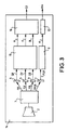
- FIG. 3 represents the block diagram of a third embodiment of a camera according to the invention.
- the camera 14 includes a lens 2, an optical splitter 3 and four sensors 4, 5, 6, 7 such as those shown in FIGS. 1 and 2.
- the electrical signals SR, SV, SB from the respective charge transfer devices 4, 5, 6 are sent into the processing circuit 15 and the electrical signal PIR from the charge transfer device 7 is sent into the processing circuit 9 .
- the processing circuit 15 makes it possible to sample and digitize the signals SR, SV, SB so as to constitute signals of colors R, G, B in 4: 4: 4 format, preferably coded on 10 bits.
- the processing circuit 9 is the same as the processing circuit with the same reference described in FIG. 1.
- the sampling frequency of the signal PIR is equal to the sampling frequency of the signals SR, SV, SB.
- a multiplexing and modulation device 16 makes it possible to generate a signal S2 consisting of multiplexed and modulated color information.
- the key signal K from the circuit processing 9 is modulated by the modulator 12 so as to constitute the modulated key signal Km.
- the processing circuit 15 makes it possible to digitize the color signals R, G, B.
- the invention also relates to the case where the color signals R, G, B are not digitized.
- the video signal S2 and the modulated key signal Km leave the camera on two separate outputs.
- FIG. 4 describes a fourth embodiment of the invention for which the video signal consisting of the color signals R, G, B and the key signal K leave the camera by a single output so as to constitute the signal ST2.
- the camera 17 includes a lens 2, an optical splitter 3, four sensors 4, 5, 6, 7 and two processing circuits 15 and 9, such as those mentioned above.
- a multiplexing and modulation device 18 makes it possible to generate a single output signal ST2.
- the output signal ST2 from the camera can then be transmitted, for example, to a television studio or a reporting car via a single cable.
- FIG. 5 represents the basic diagram of a camera head resulting from an improvement of the camera head represented in FIG. 2 or 4.
- All the circuits numbered 2, 3, 4, 5, 6, 7, 8 and 9 in FIG. 2 or 2, 3, 4, 5, 6, 7, 15 and 9 in FIG. 4 are here contained in a single block referenced 24, which also comprises a multiplexing circuit, not shown in FIG. 5, so that the signals coming from the respective elements 8 and 9, or 15 and 9 constitute a single multiplexed signal SU.
- the camera 19 comprises, in addition to the processing device 24, a video memory area 25, a compressor 26, a buffer memory 27, a circuit scrambling 28, a modulation circuit 29 and a regulation circuit 30.
- the processing device 24, the video memory area 25, the compressor 26, the buffer memory 27, the scrambling circuit 28 and the modulation circuit 29 are arranged in series.
- the subassembly constituted by the video memory area 25, the compressor 26, the buffer memory 27 and the regulation circuit 30 constitute a system making it possible to ensure a constant bit rate of the data coming from the processing device 24.
- the multiplexed signal SU from the processing device 24 consists of the video signal representing the subject in front of the background and the key signal.
- the signal SU is a digitized signal consisting either of the components Y, CB, CR, K in 4: 2: 2: 4 format coded on 10 bits, or of the components R, G, B, K in 4: 4 format: 4: 4 coded on 10 bits.
- the information from the processing device 24 is written to the video memory area 25 line by line.
- the video memory area 25 is, for example, a dual-access RAM type memory.
- the video memory area 25, the compression circuit 26 and the buffer memory 27 each include a video input and a video output.
- the buffer memory 27 also includes an auxiliary signal input and a control output.
- the compression circuit 26 also includes a compression control input and, preferably, a synchronization control input.
- the regulation circuit 30 includes a control input and a control output.
- the video output of the video memory area 25 is connected to the video input of the compressor 26 and the video output of the compressor 26 is connected to the video input of the buffer memory 27.
- the control output of the buffer memory 27 is connected to the control input of the regulation circuit 30 and the control output of the regulation circuit 30 is connected to the compression control input of the compression circuit 26.
- the compression performed by the circuit 26 is in JPEG mode and the number of lines accumulated in the video memory area 25 is at least equal to 8. More generally, however, the compression mode may be different from JPEG mode. It can be, for example, any of the MPEG modes and, more particularly, MPEG modes with reduced processing time such as, for example, the mode referenced MPEG-2 4: 2: 2 Profile Main Level (422 @ ML). It is then possible to work almost in real time.
- the control signal SC from the control output of the regulation circuit 30 is applied to the compressor 26 so as to trigger compression.
- the image is then broken down into image blocks of 8 ⁇ 8 samples corresponding to 8 image points of 81 successive lines.
- Each image block undergoes, for example, a discrete Cosine transform to provide transformed blocks of 64 coefficients. These coefficients are then quantified according to psycho-visual characteristics using rounding tables.
- the quantization carried out using rounding tables takes the duration of an image frame, ie 20 ms. More generally, the invention also relates to the cases where the quantization takes the duration of an integer number of times the duration of an image frame.
- the compressed data received from the compresser 26 is sent to a buffer memory 27.
- the buffer memory 27 is, for example, a memory of the dual access RAM type or even a memory of the FIFO type.
- the buffer memory 27 includes a counting circuit, not shown in FIG. 1. The function of the counting circuit is to count the number of times N that it has been written in the buffer memory 27 during the duration of the operation of quantification, or preferably the duration of an image frame (20 ms).
- the quantity N from the counting circuit is applied to a comparison circuit, not shown in the figure, and located at the input of the regulation circuit 30.
- the comparison circuit compares the value N with two threshold values. If N is greater than a first threshold value, the information coming from the comparison circuit controls the regulation circuit 30 so as to accentuate the compression ratio. If N is less than a second threshold value of value less than the first threshold value, the information coming from the comparison circuit controls the regulation circuit 30 so as to decrease the compression ratio. When N is between the two threshold values, the compression ratio remains unchanged.
- the first threshold value corresponds to 90% of the maximum number of data that it is possible to send on the line between two successive frames and the second threshold value corresponds to 80% of the maximum number of data that it is possible to send on the line between two successive frames. It follows that the compression of the data is not modified for a value of N of between 80% and 90% of the maximum number of data that it is possible to send on the line between two successive frames.
- the processes of increasing and decreasing the compression ratio are optimized by the planned possibility of modifying the value of the first and second thresholds by taking into account the evolution of the value of N itself .
- the regulation circuit 30 comprises a microprocessor.
- the management of the increase and decrease of the compression ratio is then carried out by programming.
- the assembly constituted by the compressor 26, the buffer memory 27 and the regulation circuit 30 starts up so as to ensure a high compression rate, such as, for example, a compression rate equal to 15, so as not to risk saturating the signal transmission.
- the regulation circuit 30 controls the compression ratio to the content of the image as a function of the value of N.
- the reference duration for carrying out the analysis which leads to the control of the compressed data is preferably equal to the duration of a frame, i.e. 20 ms.
- a synchronization signal S is applied to the analysis and processing device 24 and to the compressor 26 so as to stall in phase, relative to an external phase reference not shown in FIG. 5, the data generated by these circuits, thus making it possible to reduce the data transmission time as much as possible.
- FIGS. 5 and 6 are subjected, in a manner known per se, to different synchronization signals and to different clock signals which are not represented in these figures in order to avoid not weigh down the drawings.
- the compressor 26 uses a coding known to those skilled in the art under the name of variable length coding. It is then possible to reduce the size of words with a high probability.
- the compressor 30 includes an error correction circuit.
- the signal from the buffer memory 27 is sent to a scrambler 28 whose function is to distribute the value of the words to be transmitted equiprobably and the signal from the scrambler 28 is itself sent to a digital modulator 29.
- the digital modulator 29 relates to any type of modulation with high spectral efficiency for transmitting the information over a medium with limited bandwidth.
- the digital modulator 29 includes a filtering device adapted from the baseband before modulation, such as a Nyquist filter or a Gaussian filter.
- the carrier is synchronized with the rate of the elementary data transmitted.
- the signal V1 from the camera 19 may contain data other than that from the detection of the light signal L.
- service data DS such as parameters specific to the camera or still digital sound recording data can be introduced into the buffer memory 27 so as to be able to pass through the same channel as the video signal.
- These DS service data are introduced into the buffer memory 27 via the aforementioned auxiliary signal input.
- FIG. 6 represents the basic diagram of a control unit making it possible to process the video signal coming from a camera such as that represented in FIG. 5.
- the control unit 20 comprises, in series, a demodulator / demultiplexer 31, a descrambler 32, a decompressor 33, and a video memory area 34 and a video output interface 36.
- the control unit 20 also includes a synchronization device 35 which generates, under the action of an external time reference REF, a synchronization signal SZ applied to the memory area 34 as well as the signal S applied to the camera described in FIG. 6.
- the signal SZ advantageously makes it possible to synchronize the video signal SV coming from the control unit with other video signals, themselves synchronized with respect to the reference REF.
- a REF reference turns out to be appropriate in the case where several sources of video signals are used simultaneously.
- the function of the demodulator / demultiplexer 31 is to demodulate and demultiplex the signal V1 which it receives so as to generate a demodulated video signal Svd and a key signal Kd.
- the descrambler 32 and the decompressor 33 perform, respectively, the reverse operations of the operations performed by the scrambler 28 and the compressor 26.
- the video memory area 34 is adapted to the chosen compression mode.
- the video memory area 34 is a RAM memory type with dual access which, in the case of compression in JPEG mode, accumulates a number of lines equal to at least 8.
- the signal from the video memory area 34 is sent to the video output interface 36 whose function is to bring the video information from the control unit to the desired standard.
- the video output interface 36 can be a serializer making it possible to transform the parallel digital data coming from the video memory area 34 into serial data, or else a digital analog converter making it possible to transform the digital data coming from the video memory area 34 in analog signal, the standard of which can be, for example, the PAL, SECAM or NTSC standard.
- the key signal is also sent to the video output interface 36 so as to be set to the same standard as the video signal. According to other embodiments, however, the key signal is not set to the same standard as the video signal and leaves the control unit 20 without passing through the interface 36.
- the area of video memory 34 plays the same video frame until normal operating conditions are restored.
- the continuity of the video signal is then ensured at the output of the control unit.
- high compression ratios such as those applied at start-up, are applied to compressor 4.
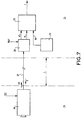
- FIG. 7 represents a complete subject inlay system using a camera such as that represented in FIG. 5 and a control unit such as that represented in FIG. 6.
- such a system includes a transmission line 21 making it possible to connect the camera to the control unit, a device 23 generating the video signal representing the new NF background on which must be embedded. the subject and a mixer 22 whose function is to generate the video image I representing the subject moving in front of the new background.
- the camera 19 is located in a first zone Z1 where the subject moving in front of the background is filmed.
- the control unit 20, the device 23 and the mixer 22 are located in a second zone Z2.
- the zones Z1 and Z2 can be in the same television studio but they can also be geographically separated so that, for example, the zone Z2 is in a different television studio at the television studio where the subject evolving in front of the film is filmed. background or in a reporting car away from the camera. Zones Z1 and Z2 are separated by a distance L.
- the control unit 20 allows demultiplexing and demodulation of the signals which it receives.
- the control unit comprises circuits making it possible to convert the signals of color into signals of luminance Y, of blue color difference CB and of red color difference CR that she receives.
- control unit 20 generates a video signal VI representing the subject moving in front of the background and the key signal K.
- the video signal VI, the key signal K, and the video signal NF representing the new background on which the subject is to be embedded are sent to the mixer 22 which has the function of generating the video image I representing the subject moving in front of the new background.
- the transmission between the camera 19 and the control unit 20 is carried out by a single transmission line of conventional structure 21, such as a coaxial or triaxial cable, a twisted pair or a two-wire line.
- a single transmission line of conventional structure 21 such as a coaxial or triaxial cable, a twisted pair or a two-wire line.
- the length L of the transmission line can vary by a few centimeters to several kilometers. For example, the transmission line can thus reach up to three kilometers.
- the video signal V1 and the synchronization signal S are carried on the same cable.
- the transmission between the camera and the control unit is carried out over the air.
- the definition of the cutting key applies to a camera.
- the invention however relates to any type of electronic device implementing the definition of the cutting key according to the invention.
- the invention also relates to autonomous cutting devices commonly called “chroma-keyers”.
- chroma-keyers autonomous cutting devices commonly called “chroma-keyers”.
- Such devices then no longer include the complex circuits which are necessary, according to the prior art, for calculating the cutting key.
Landscapes
- Engineering & Computer Science (AREA)
- Multimedia (AREA)
- Signal Processing (AREA)
- Studio Circuits (AREA)
- Processing Of Color Television Signals (AREA)
- Color Television Image Signal Generators (AREA)
Applications Claiming Priority (2)
| Application Number | Priority Date | Filing Date | Title |
|---|---|---|---|
| FR9606506A FR2749116B1 (fr) | 1996-05-24 | 1996-05-24 | Camera a effets speciaux |
| FR9606506 | 1996-05-24 |
Publications (1)
| Publication Number | Publication Date |
|---|---|
| EP0809408A1 true EP0809408A1 (fr) | 1997-11-26 |
Family
ID=9492446
Family Applications (1)
| Application Number | Title | Priority Date | Filing Date |
|---|---|---|---|
| EP97401129A Ceased EP0809408A1 (fr) | 1996-05-24 | 1997-05-23 | Caméra à effets spéciaux |
Country Status (4)
| Country | Link |
|---|---|
| US (1) | US6124887A (enExample) |
| EP (1) | EP0809408A1 (enExample) |
| JP (1) | JPH1051803A (enExample) |
| FR (1) | FR2749116B1 (enExample) |
Families Citing this family (8)
| Publication number | Priority date | Publication date | Assignee | Title |
|---|---|---|---|---|
| US6400766B1 (en) * | 1999-12-30 | 2002-06-04 | Quikcat.Com, Inc. | Method and apparatus for digital video compression using three-dimensional cellular automata transforms |
| EP1395062A1 (en) * | 2002-09-02 | 2004-03-03 | Thomson Licensing S.A. | Color image pickup device |
| EP1617650A1 (en) * | 2004-07-14 | 2006-01-18 | Thomson Licensing | Video signal transceiver |
| JP2006243940A (ja) * | 2005-03-01 | 2006-09-14 | Oki Electric Ind Co Ltd | カメラデータ転送装置 |
| AR064274A1 (es) * | 2006-12-14 | 2009-03-25 | Panasonic Corp | Metodo de codificacion de imagenes en movimiento, dispositivo de codificacion de imagenes en movimiento, metodo de grabacion de imagenes en movimiento, medio de grabacion, metodo de reproduccion de imagenes en movimiento, dispositivo de reproduccion de imagenes en movimiento, y sistema de reproducci |
| JP2008205871A (ja) * | 2007-02-21 | 2008-09-04 | Megachips Lsi Solutions Inc | 撮像ユニット、携帯端末装置、および携帯端末システム |
| PE20140057A1 (es) | 2010-09-20 | 2014-03-01 | Fraunhofer Ges Forschung | Metodo para diferenciar entre el fondo y el frente del escenario y tambien metodo para reemplazar un fondo en las imagenes de un decorado |
| CN114051145B (zh) * | 2022-01-11 | 2022-04-22 | 苏州浪潮智能科技有限公司 | 一种视频压缩处理方法、装置及介质 |
Citations (6)
| Publication number | Priority date | Publication date | Assignee | Title |
|---|---|---|---|---|
| GB1539199A (en) * | 1977-12-02 | 1979-01-31 | British Broadcasting Corp | Colour television |
| JPH0437383A (ja) * | 1990-06-01 | 1992-02-07 | Nippon Hoso Kyokai <Nhk> | 画像合成方法と装置 |
| JPH0447871A (ja) * | 1990-06-15 | 1992-02-18 | Nippon Telegr & Teleph Corp <Ntt> | 物体抽出装置 |
| WO1994026057A1 (en) * | 1993-04-29 | 1994-11-10 | Scientific Generics Limited | Background separation for still and moving images |
| JPH077665A (ja) * | 1993-06-14 | 1995-01-10 | Canon Inc | 画像抽出装置 |
| JPH07154777A (ja) * | 1993-11-30 | 1995-06-16 | Matsushita Electric Ind Co Ltd | 画像処理装置およびテレビ電話装置 |
Family Cites Families (3)
| Publication number | Priority date | Publication date | Assignee | Title |
|---|---|---|---|---|
| US3806633A (en) * | 1972-01-18 | 1974-04-23 | Westinghouse Electric Corp | Multispectral data sensor and display system |
| DE3905591C2 (de) * | 1989-02-23 | 1997-08-28 | Rheinmetall Ind Ag | Vorrichtung zur Gewinnung kontrastreicher Bilder |
| US5982423A (en) * | 1996-08-13 | 1999-11-09 | Sony Corporation | Video photographing apparatus having infrared rays AV transmitting function |
-
1996
- 1996-05-24 FR FR9606506A patent/FR2749116B1/fr not_active Expired - Fee Related
-
1997
- 1997-05-14 US US08/855,956 patent/US6124887A/en not_active Expired - Lifetime
- 1997-05-19 JP JP9128628A patent/JPH1051803A/ja active Pending
- 1997-05-23 EP EP97401129A patent/EP0809408A1/fr not_active Ceased
Patent Citations (6)
| Publication number | Priority date | Publication date | Assignee | Title |
|---|---|---|---|---|
| GB1539199A (en) * | 1977-12-02 | 1979-01-31 | British Broadcasting Corp | Colour television |
| JPH0437383A (ja) * | 1990-06-01 | 1992-02-07 | Nippon Hoso Kyokai <Nhk> | 画像合成方法と装置 |
| JPH0447871A (ja) * | 1990-06-15 | 1992-02-18 | Nippon Telegr & Teleph Corp <Ntt> | 物体抽出装置 |
| WO1994026057A1 (en) * | 1993-04-29 | 1994-11-10 | Scientific Generics Limited | Background separation for still and moving images |
| JPH077665A (ja) * | 1993-06-14 | 1995-01-10 | Canon Inc | 画像抽出装置 |
| JPH07154777A (ja) * | 1993-11-30 | 1995-06-16 | Matsushita Electric Ind Co Ltd | 画像処理装置およびテレビ電話装置 |
Non-Patent Citations (4)
| Title |
|---|
| PATENT ABSTRACTS OF JAPAN vol. 016, no. 221 (E - 1205) 22 May 1992 (1992-05-22) * |
| PATENT ABSTRACTS OF JAPAN vol. 016, no. 236 (E - 1210) 29 May 1992 (1992-05-29) * |
| PATENT ABSTRACTS OF JAPAN vol. 95, no. 001 * |
| PATENT ABSTRACTS OF JAPAN vol. 95, no. 006 * |
Also Published As
| Publication number | Publication date |
|---|---|
| JPH1051803A (ja) | 1998-02-20 |
| FR2749116A1 (fr) | 1997-11-28 |
| US6124887A (en) | 2000-09-26 |
| FR2749116B1 (fr) | 1998-06-19 |
Similar Documents
| Publication | Publication Date | Title |
|---|---|---|
| US20190349537A1 (en) | Apparatus and method for combining images | |
| EP0271122B1 (fr) | Système pour transmettre des images de télévision haute définition dans des canaux à bande étroite, ainsi qu'un émetteur et un récepteur convenant pour le système | |
| EP1142315B1 (fr) | Systeme d'insertion visuelle dans une sequence video | |
| FR2832892A1 (fr) | Camera video d'effets speciaux | |
| EP0540403B1 (fr) | Système d'analyse vidéo du montage d'un programme télévisé diffusé ou enregistré et son utilisation pour les techniques de post production, notamment multilingues | |
| FR2590099A1 (fr) | Procede pour transmettre une image de haute definition par un canal de communication a bande etroite | |
| FR2503968A1 (fr) | Generateur de signal de decoupage pour la realisation d'incrustations en television en couleur | |
| FR2462692A1 (fr) | Dispositif de mesure multiple du champ objet d'un appareil de prise de vues | |
| EP0330279A1 (fr) | Dispositif de sous-échantillonnage spatio-temporel de signaux vidéo numériques représentatifs d'une suite d'images entrelacées ou séquentielles, système de transmission d'images de télévision à haute définition incluant un tel dispositif, et étages d'émission et de réception pour un tel système | |
| FR2519501A1 (fr) | Systeme de television stereoscopique | |
| FR2648656A1 (fr) | Systeme d'enregistrement et de reproduction dans un appareil video a image fixe | |
| EP0809408A1 (fr) | Caméra à effets spéciaux | |
| EP0416985A1 (fr) | Procédé de multiplexage d'un signal sonore avec un signal vidéo analogique et système correspondant de distribution d'images fixes sonorisées | |
| FR2702914A1 (fr) | Dispositif de codage de suites d'images constituées d'images de nature film et d'images de nature vidéo, et dispositif de décodage correspondant. | |
| CA2961118A1 (fr) | Dispositif d'acquisition d'images bimode a photocathode | |
| FR2698509A1 (fr) | Ensemble de sélection d'un facteur de compression de données pour appareil de prise de vues. | |
| FR2543387A1 (enExample) | ||
| EP0135405A1 (fr) | Procédé et dispositif de détection de points en mouvement dans une image de télévision pour systèmes de télévision numérique de compression de débit à rafraîchissement conditionnel | |
| FR2838016A1 (fr) | Procede de traitement en temps reel d'un signal representatif d'une image | |
| EP1217831A1 (fr) | Procédé et dispositif de filtrage des données relatives au guide électronique de programmes d'un téléviseur | |
| WO2019166720A1 (fr) | Détection dynamique de lumière parasite dans une image numérique | |
| FR2556543A1 (fr) | Appareil de separation de signal de couleur | |
| FR2863755A1 (fr) | Procede et systeme d'identification d'un vehicule en deplacement | |
| EP0809397B1 (fr) | Camera vidéo numérique à débit sensiblement constant et système de transmission utilisant une telle camera | |
| EP0350122A1 (fr) | Procédés et dispositifs de codage et de décodage d'images de télévision à haute définition et systèmes de transmission d'images de télévision incluant de tels dispositifs |
Legal Events
| Date | Code | Title | Description |
|---|---|---|---|
| PUAI | Public reference made under article 153(3) epc to a published international application that has entered the european phase |
Free format text: ORIGINAL CODE: 0009012 |
|
| AK | Designated contracting states |
Kind code of ref document: A1 Designated state(s): DE FR GB |
|
| 17P | Request for examination filed |
Effective date: 19980520 |
|
| 17Q | First examination report despatched |
Effective date: 20050316 |
|
| STAA | Information on the status of an ep patent application or granted ep patent |
Free format text: STATUS: THE APPLICATION HAS BEEN REFUSED |
|
| 18R | Application refused |
Effective date: 20100213 |