EP0809265A2 - Name bearing plate with locking elements for quickly locking outer push-buttons - Google Patents
Name bearing plate with locking elements for quickly locking outer push-buttons Download PDFInfo
- Publication number
- EP0809265A2 EP0809265A2 EP96830520A EP96830520A EP0809265A2 EP 0809265 A2 EP0809265 A2 EP 0809265A2 EP 96830520 A EP96830520 A EP 96830520A EP 96830520 A EP96830520 A EP 96830520A EP 0809265 A2 EP0809265 A2 EP 0809265A2
- Authority
- EP
- European Patent Office
- Prior art keywords
- push
- bearing plate
- name bearing
- button
- locking
- Prior art date
- Legal status (The legal status is an assumption and is not a legal conclusion. Google has not performed a legal analysis and makes no representation as to the accuracy of the status listed.)
- Withdrawn
Links
- 239000011521 glass Substances 0.000 claims abstract description 14
- 230000008878 coupling Effects 0.000 claims abstract description 7
- 238000010168 coupling process Methods 0.000 claims abstract description 7
- 238000005859 coupling reaction Methods 0.000 claims abstract description 7
- 238000010276 construction Methods 0.000 claims description 12
- 229910001369 Brass Inorganic materials 0.000 claims description 7
- 239000010951 brass Substances 0.000 claims description 7
- 239000000463 material Substances 0.000 claims description 6
- 210000002105 tongue Anatomy 0.000 claims description 4
- 239000012777 electrically insulating material Substances 0.000 claims 1
- 230000000452 restraining effect Effects 0.000 description 4
- 230000002860 competitive effect Effects 0.000 description 1
- 238000010292 electrical insulation Methods 0.000 description 1
- 238000000034 method Methods 0.000 description 1
Images


Classifications
-
- G—PHYSICS
- G09—EDUCATION; CRYPTOGRAPHY; DISPLAY; ADVERTISING; SEALS
- G09F—DISPLAYING; ADVERTISING; SIGNS; LABELS OR NAME-PLATES; SEALS
- G09F7/00—Signs, name or number plates, letters, numerals, or symbols; Panels or boards
- G09F7/18—Means for attaching signs, plates, panels, or boards to a supporting structure
-
- G—PHYSICS
- G09—EDUCATION; CRYPTOGRAPHY; DISPLAY; ADVERTISING; SEALS
- G09F—DISPLAYING; ADVERTISING; SIGNS; LABELS OR NAME-PLATES; SEALS
- G09F13/00—Illuminated signs; Luminous advertising
- G09F13/04—Signs, boards or panels, illuminated from behind the insignia
-
- G—PHYSICS
- G09—EDUCATION; CRYPTOGRAPHY; DISPLAY; ADVERTISING; SEALS
- G09F—DISPLAYING; ADVERTISING; SIGNS; LABELS OR NAME-PLATES; SEALS
- G09F13/00—Illuminated signs; Luminous advertising
- G09F13/04—Signs, boards or panels, illuminated from behind the insignia
- G09F13/0418—Constructional details
- G09F13/0427—Constructional details in the form of buttons
-
- G—PHYSICS
- G09—EDUCATION; CRYPTOGRAPHY; DISPLAY; ADVERTISING; SEALS
- G09F—DISPLAYING; ADVERTISING; SIGNS; LABELS OR NAME-PLATES; SEALS
- G09F13/00—Illuminated signs; Luminous advertising
- G09F13/04—Signs, boards or panels, illuminated from behind the insignia
- G09F13/0418—Constructional details
- G09F13/045—Signs, boards or panels specially adapted for doors
-
- G—PHYSICS
- G09—EDUCATION; CRYPTOGRAPHY; DISPLAY; ADVERTISING; SEALS
- G09F—DISPLAYING; ADVERTISING; SIGNS; LABELS OR NAME-PLATES; SEALS
- G09F13/00—Illuminated signs; Luminous advertising
- G09F13/04—Signs, boards or panels, illuminated from behind the insignia
- G09F13/0418—Constructional details
- G09F13/0454—Slidable panels or parts
-
- G—PHYSICS
- G09—EDUCATION; CRYPTOGRAPHY; DISPLAY; ADVERTISING; SEALS
- G09F—DISPLAYING; ADVERTISING; SIGNS; LABELS OR NAME-PLATES; SEALS
- G09F13/00—Illuminated signs; Luminous advertising
- G09F13/04—Signs, boards or panels, illuminated from behind the insignia
- G09F13/0409—Arrangements for homogeneous illumination of the display surface, e.g. using a layer having a non-uniform transparency
Definitions
- the present invention relates to a name bearing plate with locking elements for quickly locking outer push-buttons.
- the aim of the present invention is to overcome the above mentioned drawbacks, by providing a name bearing plate construction with means for quickly locking outer push-buttons, and in particular affording the possibility of performing, in a brass name bearing plate, a snap coupling of the outer push-button, without the need of using assembling tools or instruments.
- a main object of the present invention is to provide such a name bearing plate in which the electrical insulating operation can be performed in a very simple manner, thereby solving all of the related electrical connecting operation problems.
- Another object of the present invention is to provide such a name bearing plate construction which, owing to its specifically designed configuration, is very reliable and safe in operation.
- Yet another object of the present invention is to provide such a name bearing plate construction, including locking means for quickly locking the outer push-buttons, which can be easily made starting from easily commercially available elements and materials and which, moreover, is very competitive from a mere economic standpoint.
- a name bearing plate construction with locking means for quickly locking the outer push-buttons, comprising a plate body having a plurality of windows for the name bearing glass elements adjoining push-button holes, characterized in that said name bearing glass elements define quick coupling means for locking the body of the push-button.
- the name bearing plate construction with locking means for quickly locking the outer push-buttons according to the present invention which has been generally indicated by the reference number 1, comprises a brass material plate, which is provided with a plurality of windows 3, which can be arranged in an adjoining mutual relationship, by pairs, or which can be provided as single mutually superimposed elements.
- a name bearing glass element is coupled, which element can be either of a double type, as shown in figures 3 to 5, or of a single type, as shown in figures 6 and 7.
- Each name bearing glass element defines an increased thickness region 11, which engages within the windows 3 and being provided with longitudinal side edges 12 having coupling tooth elements 13, in order to allow sheet element restraining elements 15 to be engaged therein, said restraining element 15 being provided with lugs 16 to be arranged between the tooth elements 13 for allowing application and removal operations to be easily performed.
- Adjoining the windows 3 are provided a plurality of holes, indicated by the reference number 18, in which push buttons, generally indicated by the reference number 20, can be engaged.
- the push-buttons 20 have a hollow push-button body 21 in the inside of which a slider 22 is provided, also made of a brass material, and being connected to one end of a pin element 23 provided, on end arm portions 24 thereof, with a ring like enlarged portion 25 snap engaging inside an annular groove 26 as formed on the slider.
- a spring 27 is moreover provided for operating between the push-button and innert bottom of the push-body 21.
- the push-body 21 is provided, on the outer surface thereof, with a cut-out 30 being delimitated by an abutment element 31.
- quick connecting means can be engaged, said quick connecting means being defined by the glass elements 10 and comprising resilient tongues 35 engaging in the cut-out 30 and abutting against the abutment element 31 thereby allowing the push-button 20 to be quickly and easily locked inside the plate 2.
- the push-button can be easily connected and locked by simply engaging the push-button body 21 inside the tongues 35, which in turn engage in the cut-out or groove 30 thereby providing a firm locking.
- the push-button can be quickly and easily assembled since said pin can be coupled to said slider by a simple pressing operation; the latter will cause the arm elements 23 to be deflected, so as to cause the enlarged portion 25 defined at the end parts of said arms of said pin to be easily engaged in the groove 26 of the slider.
- the used materials provided that they are compatible to the intended application, as well as the contingent size and shapes, can be any, depending on requirements.
Landscapes
- Physics & Mathematics (AREA)
- General Physics & Mathematics (AREA)
- Engineering & Computer Science (AREA)
- Theoretical Computer Science (AREA)
- Push-Button Switches (AREA)
- Slot Machines And Peripheral Devices (AREA)
- Fittings On The Vehicle Exterior For Carrying Loads, And Devices For Holding Or Mounting Articles (AREA)
- Casings For Electric Apparatus (AREA)
Abstract
Description
- The present invention relates to a name bearing plate with locking elements for quickly locking outer push-buttons.
- As is known, in making brass name bearing plates great difficulties are at present encountered for coupling the ring push-buttons, which are also conventionally made of a brass material.
- Actually, it is conventionally necessary to assemble several component elements by screw-type of connections, which have a comparatively high cost and require a comparatively long assembling time.
- Moreover, problems are frequently encountered in performing a proper electrical insulation, since it is necessary to adopt specifically designed insulating processes.
- Accordingly, the aim of the present invention is to overcome the above mentioned drawbacks, by providing a name bearing plate construction with means for quickly locking outer push-buttons, and in particular affording the possibility of performing, in a brass name bearing plate, a snap coupling of the outer push-button, without the need of using assembling tools or instruments.
- Within the scope of the above mentioned aim, a main object of the present invention is to provide such a name bearing plate in which the electrical insulating operation can be performed in a very simple manner, thereby solving all of the related electrical connecting operation problems.
- Another object of the present invention is to provide such a name bearing plate construction which, owing to its specifically designed configuration, is very reliable and safe in operation.
- Yet another object of the present invention is to provide such a name bearing plate construction, including locking means for quickly locking the outer push-buttons, which can be easily made starting from easily commercially available elements and materials and which, moreover, is very competitive from a mere economic standpoint.
- According to one aspect of the present invention, the above mentioned aim and objects, as well as yet other objects, which will become more apparent hereinafter, are achieved by a name bearing plate construction, with locking means for quickly locking the outer push-buttons, comprising a plate body having a plurality of windows for the name bearing glass elements adjoining push-button holes, characterized in that said name bearing glass elements define quick coupling means for locking the body of the push-button.
- Further characteristics and advantages of the present invention will become more apparent hereinafter from the following detailed disclosure of a name bearing plate construction with locking means for quickly locking the outer push-buttons, and being illustrated by way of an indicative, but not limitative example, in the accompanying drawings, where:
- Figure 1 is a cross sectional view illustrating a name bearing plate with adjoining windows therethrough;
- Figure 2 is a cross sectional view substantially taken along the section line II-II of Figure 1;
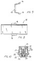
- Figure 3 illustrates a name bearing glass element provided for bearing two names;
- Figure 4 is an elevation side view illustrating a name bearing glass element, as partially cross-sectioned;
- Figure 5 is a view from inside illustrating a double name bearing glass element;
- Figure 6 is another view from inside illustrating a single name bearing glass element;
- Figure 7 is a cross sectional view substantially taken along the section line VII-VII of Figure 6;
- Figure 8 is a top plan view illustrating a name bearing sheet restraining element;
- Figure 9 is an end view illustrating that same sheet restraining element; and
- Figure 10 is a cross sectional view illustrating a push-button.
- With reference to the number reference of the above mentioned figures, the name bearing plate construction with locking means for quickly locking the outer push-buttons according to the present invention, which has been generally indicated by the reference number 1, comprises a brass material plate, which is provided with a plurality of
windows 3, which can be arranged in an adjoining mutual relationship, by pairs, or which can be provided as single mutually superimposed elements. - At the
windows 3, a name bearing glass element, generally indicated by thereference number 10, is coupled, which element can be either of a double type, as shown in figures 3 to 5, or of a single type, as shown in figures 6 and 7. - Each name bearing glass element defines an increased
thickness region 11, which engages within thewindows 3 and being provided withlongitudinal side edges 12 havingcoupling tooth elements 13, in order to allow sheetelement restraining elements 15 to be engaged therein, said restrainingelement 15 being provided withlugs 16 to be arranged between thetooth elements 13 for allowing application and removal operations to be easily performed. - Adjoining the
windows 3 are provided a plurality of holes, indicated by thereference number 18, in which push buttons, generally indicated by thereference number 20, can be engaged. - More specifically, the push-
buttons 20 have a hollow push-button body 21 in the inside of which aslider 22 is provided, also made of a brass material, and being connected to one end of apin element 23 provided, onend arm portions 24 thereof, with a ring like enlargedportion 25 snap engaging inside anannular groove 26 as formed on the slider. - A spring 27 is moreover provided for operating between the push-button and innert bottom of the push-
body 21. - The push-
body 21 is provided, on the outer surface thereof, with a cut-out 30 being delimitated by anabutment element 31. - In the cut-out 30 quick connecting means can be engaged, said quick connecting means being defined by the
glass elements 10 and comprisingresilient tongues 35 engaging in the cut-out 30 and abutting against theabutment element 31 thereby allowing the push-button 20 to be quickly and easily locked inside theplate 2. - From the above disclosure it should be apparent that the invention fully achieves the intended aim and objects.
- In particular, the fact is to be pointed out that the push-button can be easily connected and locked by simply engaging the push-
button body 21 inside thetongues 35, which in turn engage in the cut-out orgroove 30 thereby providing a firm locking. - To the foregoing it is to be added that also the push-button can be quickly and easily assembled since said pin can be coupled to said slider by a simple pressing operation; the latter will cause the
arm elements 23 to be deflected, so as to cause the enlargedportion 25 defined at the end parts of said arms of said pin to be easily engaged in thegroove 26 of the slider. - In practicing the invention, the used materials, provided that they are compatible to the intended application, as well as the contingent size and shapes, can be any, depending on requirements.
Claims (6)
- A name bearing plate construction, with locking means for quickly locking the outer push-buttons, comprising a plate-like body having a plurality of windows for the name bearing glass elements and adjoining holes for receiving respective push-buttons, characterized in that said name bearing glass elements define quick coupling means for locking the push-button body.
- A name bearing plate construction, according to the preceding claim, characterized in that said plate like body and the body of the push-button are made of a brass material.
- A name bearing plate construction, according to one or more of the preceding claims, characterized in that said quick coupling means comprise resilient tongues defined by said glass elements about an opening in which can be engaged the push-button body and having a cut-out delimited by an abutment element which can be engaged with the end portions of said resilient tongues.
- A name bearing plate construction, according to one or more of the preceding claims, characterized in that said push-button is provided with a brass slider, which is removably coupled to an electrically insulating material pin housed inside said push-button body.
- A name bearing plate construction, according to one or more of the preceding claims, characterized in that said pin is provided with a pair of mutually flexible arms being provided with a projecting ring element which can be engaged in a groove correspondingly formed on said slider.
- A name bearing plate construction, according to one or more of the preceding claims, characterized in that said push-button body is provided, at the end portion thereof opposite to that defining said cut-out with an abutment edge which can be coupled about said push-button hole.
Applications Claiming Priority (2)
| Application Number | Priority Date | Filing Date | Title |
|---|---|---|---|
| ITMI960401 | 1996-03-01 | ||
| IT1996MI000401U IT240702Y1 (en) | 1996-05-24 | 1996-05-24 | NAME HOLDER STRUCTURE WITH QUICK LOCKING DEVICES FOR EXTERNAL BUTTONS |
Publications (2)
| Publication Number | Publication Date |
|---|---|
| EP0809265A2 true EP0809265A2 (en) | 1997-11-26 |
| EP0809265A3 EP0809265A3 (en) | 1998-07-15 |
Family
ID=11373465
Family Applications (2)
| Application Number | Title | Priority Date | Filing Date |
|---|---|---|---|
| EP96830520A Withdrawn EP0809265A3 (en) | 1996-05-24 | 1996-10-11 | Name bearing plate with locking elements for quickly locking outer push-buttons |
| EP97830213A Expired - Lifetime EP0809224B1 (en) | 1996-05-24 | 1997-05-09 | Name bearing plate provided with quick locking means for locking the outer push-buttons |
Family Applications After (1)
| Application Number | Title | Priority Date | Filing Date |
|---|---|---|---|
| EP97830213A Expired - Lifetime EP0809224B1 (en) | 1996-05-24 | 1997-05-09 | Name bearing plate provided with quick locking means for locking the outer push-buttons |
Country Status (5)
| Country | Link |
|---|---|
| EP (2) | EP0809265A3 (en) |
| DE (1) | DE69707971T2 (en) |
| ES (1) | ES2167698T3 (en) |
| IT (1) | IT240702Y1 (en) |
| PT (1) | PT809224E (en) |
Family Cites Families (5)
| Publication number | Priority date | Publication date | Assignee | Title |
|---|---|---|---|---|
| CH654944A5 (en) * | 1981-10-23 | 1986-03-14 | Autelca Ag | Board with signs |
| DE3602283A1 (en) * | 1986-01-25 | 1987-07-30 | Ulrich Lippert Kg | Name-plate |
| DE4004337C1 (en) * | 1990-02-13 | 1991-06-06 | Ritto-Werk Loh Gmbh & Co Kg, 6342 Haiger, De | Door bell switch - has actuator panel formed with slot and has location for name card |
| DE4433162C2 (en) * | 1994-09-17 | 1999-11-11 | Lira Elektrotechnische Fabrik | Name plate buttons |
| DE4447176A1 (en) * | 1994-12-30 | 1996-07-04 | Lira Elektrotechnische Fabrik | Anti-vandalism type pushbutton actuated door bell system |
-
1996
- 1996-05-24 IT IT1996MI000401U patent/IT240702Y1/en active
- 1996-10-11 EP EP96830520A patent/EP0809265A3/en not_active Withdrawn
-
1997
- 1997-05-09 PT PT97830213T patent/PT809224E/en unknown
- 1997-05-09 DE DE69707971T patent/DE69707971T2/en not_active Expired - Fee Related
- 1997-05-09 EP EP97830213A patent/EP0809224B1/en not_active Expired - Lifetime
- 1997-05-09 ES ES97830213T patent/ES2167698T3/en not_active Expired - Lifetime
Non-Patent Citations (1)
| Title |
|---|
| None |
Also Published As
| Publication number | Publication date |
|---|---|
| ES2167698T3 (en) | 2002-05-16 |
| ITMI960401V0 (en) | 1996-05-24 |
| EP0809265A3 (en) | 1998-07-15 |
| EP0809224B1 (en) | 2001-11-07 |
| EP0809224A3 (en) | 1999-05-06 |
| EP0809224A2 (en) | 1997-11-26 |
| PT809224E (en) | 2002-04-29 |
| DE69707971D1 (en) | 2001-12-13 |
| DE69707971T2 (en) | 2002-06-27 |
| ITMI960401U1 (en) | 1997-11-24 |
| IT240702Y1 (en) | 2001-04-11 |
Similar Documents
| Publication | Publication Date | Title |
|---|---|---|
| US4072840A (en) | Removable keyboard switch | |
| EP0007709B1 (en) | Electrical connector | |
| US4027936A (en) | Connector having electro-conductive rubber terminal | |
| EP0920040A3 (en) | Dual tact switch assembly | |
| EP3790116A1 (en) | Connector and connector manufacturing method | |
| US4945195A (en) | Rotary switch | |
| US4331377A (en) | Terminal, preferably for mounting on circuit boards of printed circuits | |
| GB2375657A (en) | Multiple switched socket outlet | |
| EP0067524A1 (en) | Fastener for assembling two hollow members | |
| US4611880A (en) | Multipiece electrical connector | |
| EP0809265A2 (en) | Name bearing plate with locking elements for quickly locking outer push-buttons | |
| US5194703A (en) | Push-button arrangement | |
| US4894500A (en) | Rotary selector switch | |
| EP0484289A2 (en) | A connector for an electronic control unit | |
| EP0279784B1 (en) | Push button assembly structure specifically designed for controlling motor vehicle glass raising and lowering devices | |
| JPH0338739Y2 (en) | ||
| KR900005827Y1 (en) | Multi-stage knob | |
| JPH0212656Y2 (en) | ||
| EP1580857B1 (en) | Cable trunking and ducting | |
| JPH0348853Y2 (en) | ||
| JPH049709Y2 (en) | ||
| JPH0346393Y2 (en) | ||
| JPS6125179Y2 (en) | ||
| US4727526A (en) | Alarm on-off mechanism for alarm watch | |
| US4518834A (en) | Matrix slide switch |
Legal Events
| Date | Code | Title | Description |
|---|---|---|---|
| PUAI | Public reference made under article 153(3) epc to a published international application that has entered the european phase |
Free format text: ORIGINAL CODE: 0009012 |
|
| AK | Designated contracting states |
Kind code of ref document: A2 Designated state(s): AT BE CH DE ES FR GB GR IT LI NL |
|
| AX | Request for extension of the european patent |
Free format text: SI PAYMENT 961021 |
|
| PUAL | Search report despatched |
Free format text: ORIGINAL CODE: 0009013 |
|
| AK | Designated contracting states |
Kind code of ref document: A3 Designated state(s): AT BE CH DE ES FR GB GR IT LI NL |
|
| AX | Request for extension of the european patent |
Free format text: SI PAYMENT 961021 |
|
| 17P | Request for examination filed |
Effective date: 19980928 |
|
| 17Q | First examination report despatched |
Effective date: 20020208 |
|
| STAA | Information on the status of an ep patent application or granted ep patent |
Free format text: STATUS: THE APPLICATION IS DEEMED TO BE WITHDRAWN |
|
| 18D | Application deemed to be withdrawn |
Effective date: 20020820 |