EP0809079A1 - Wasserumwälzanlage mit Wasserstrahlpumpe - Google Patents
Wasserumwälzanlage mit Wasserstrahlpumpe Download PDFInfo
- Publication number
- EP0809079A1 EP0809079A1 EP96303555A EP96303555A EP0809079A1 EP 0809079 A1 EP0809079 A1 EP 0809079A1 EP 96303555 A EP96303555 A EP 96303555A EP 96303555 A EP96303555 A EP 96303555A EP 0809079 A1 EP0809079 A1 EP 0809079A1
- Authority
- EP
- European Patent Office
- Prior art keywords
- water
- cold water
- hot water
- check valve
- aspirator
- Prior art date
- Legal status (The legal status is an assumption and is not a legal conclusion. Google has not performed a legal analysis and makes no representation as to the accuracy of the status listed.)
- Withdrawn
Links
- XLYOFNOQVPJJNP-UHFFFAOYSA-N water Substances O XLYOFNOQVPJJNP-UHFFFAOYSA-N 0.000 title claims abstract description 239
- 238000000034 method Methods 0.000 claims description 4
- 238000011144 upstream manufacturing Methods 0.000 claims 4
- 238000007599 discharging Methods 0.000 claims 2
- 230000008878 coupling Effects 0.000 claims 1
- 238000010168 coupling process Methods 0.000 claims 1
- 238000005859 coupling reaction Methods 0.000 claims 1
- 238000009434 installation Methods 0.000 abstract description 13
- 239000002699 waste material Substances 0.000 abstract description 5
- 230000001105 regulatory effect Effects 0.000 abstract description 4
- 210000002445 nipple Anatomy 0.000 description 4
- 238000012360 testing method Methods 0.000 description 4
- 238000013459 approach Methods 0.000 description 3
- 230000007935 neutral effect Effects 0.000 description 3
- 238000013461 design Methods 0.000 description 2
- 230000009977 dual effect Effects 0.000 description 2
- 230000000694 effects Effects 0.000 description 2
- 238000010438 heat treatment Methods 0.000 description 2
- 238000012423 maintenance Methods 0.000 description 2
- 239000000463 material Substances 0.000 description 2
- 241001122767 Theaceae Species 0.000 description 1
- 230000001154 acute effect Effects 0.000 description 1
- 238000004458 analytical method Methods 0.000 description 1
- 235000012206 bottled water Nutrition 0.000 description 1
- 230000006835 compression Effects 0.000 description 1
- 238000007906 compression Methods 0.000 description 1
- 238000010276 construction Methods 0.000 description 1
- 239000003651 drinking water Substances 0.000 description 1
- 230000005611 electricity Effects 0.000 description 1
- 230000005484 gravity Effects 0.000 description 1
- 238000002347 injection Methods 0.000 description 1
- 239000007924 injection Substances 0.000 description 1
- 238000004519 manufacturing process Methods 0.000 description 1
- 239000002184 metal Substances 0.000 description 1
- 230000009972 noncorrosive effect Effects 0.000 description 1
- 230000000737 periodic effect Effects 0.000 description 1
- 238000009428 plumbing Methods 0.000 description 1
- 230000004044 response Effects 0.000 description 1
- 230000025508 response to water Effects 0.000 description 1
- 235000014347 soups Nutrition 0.000 description 1
- 229910001220 stainless steel Inorganic materials 0.000 description 1
- 239000010935 stainless steel Substances 0.000 description 1
- 239000013589 supplement Substances 0.000 description 1
Images
Classifications
-
- F—MECHANICAL ENGINEERING; LIGHTING; HEATING; WEAPONS; BLASTING
- F24—HEATING; RANGES; VENTILATING
- F24D—DOMESTIC- OR SPACE-HEATING SYSTEMS, e.g. CENTRAL HEATING SYSTEMS; DOMESTIC HOT-WATER SUPPLY SYSTEMS; ELEMENTS OR COMPONENTS THEREFOR
- F24D17/00—Domestic hot-water supply systems
- F24D17/0078—Recirculation systems
Definitions
- This invention relates to quickly providing and maintaining hot water to remote faucets in residential and small commercial buildings.
- Auxiliary heaters as shown in U.S. Patent No. 4,236,548 to Howard, 2 December, 1980 can be used to provide instant hot water to remote outlets, however the cost of initial procurement and installation is a significant drawback. They require connection to gas (and necessary vent stack) or electricity for their energy source. Operational costs will also be incurred. Heaters made for installation under the counter are designed to serve extremely hot water (approximately 80 to 85 degrees C.) for direct use in coffee, tea or soups without further heating. These heaters usually contain only a small volume of hot water (3 to 5 litres), and constitute a potential safety hazard due to their extreme temperature.
- the recently patented Dual Mode Hot Water Circulation Apparatus uses a cold water heat exchanger to induce a low rate convective circulation flow, plus an aspirator to supplement the convective flow with a higher rate circulation flow in response to water use in the building.
- This system yields excellent results, with hot water immediately available at any time, day or night.
- the length of the heat exchanger requires a space l to 1.5 meters long at an angle to the horizontal where the unit can be installed in the water supply pipe. This space may not always be available.
- the Dual Mode Hot Water Circulation Apparatus performs extremely well, material and manufacturing costs for it will be higher than for the present invention.
- the object of this invention is to provide instantly available hot water to remote faucets in residential or small commercial buildings. Additional objects and advantages of the present invention are as follows:
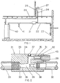
- a water circulation unit consists of an aspirator and a check valve in a housing (body), and fittings for installation into the building cold water pipe and connection to a small water return line.
- the water circulation unit 21 is installed in the building water supply pipe 22 downstream of the takeoff 23 for outside water outlets and lawn sprinkler systems.
- the water return line 24 leads from a tee 25 installed in the hot water pipe 26 (insulated for best performance) at the remote faucet 27, to a fitting on the circulation unit.
- the unit is capable of withstanding domestic water supply pressures.
- the water return line 24 is a small tube, nominally 1.0 cm outside diameter, of a length determined by each installation. It will typically be installed with flare or compression fittings.
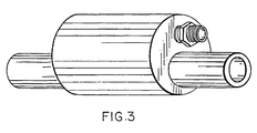
- the body 29 is a cylindrical or similar shaped structure constructed of non-corrosive metal or plastic compatible with use in potable water systems, and may be cast, machined, or injection molded.
- the aspirator 30 and check valve 31 are integral to the body 29, each having a separate bore.
- the unit has inlet and outlet pipe nipples 32 and 33 respectively, compatible with installation in the cold water pipe in most domestic or small commercial buildings according to standard plumbing practices.
- An internal passageway 34 leads from the outlet end of the check valve bore 35 to the aspirator bore 36. This passageway is closed from the exterior by a plug 37 installed in the body 29.
- the following elements are located in or attached to the body 29:
- the unit establishes a hot water circulation flow any time that a faucet is open and water is flowing in the building.
- the circulation flow is caused by the aspirator 30 located internal to the circulation unit 21.
- the reduced cross section of the aspirator nozzle 38 causes a high velocity in the water passing through the nozzle.
- the high velocity water reduces the pressure in the low pressure chamber 39 of the aspirator bore 36.
- the opening of the internal passageway 34 into the aspirator bore 36 is located in this chamber.
- the low pressure causes water to be drawn through the return line 24, through the check valve 31, and into the main stream flowing to the water heater 40. This water is replaced by water from the heater 40 flowing through the hot water pipe 26 to the tee 25 at the remote faucet 27, thereby establishing the circulation loop, and providing hot water to the remote faucet.
- the unit produces a circulation flow rate sufficient to quickly provide hot water at the remote faucet with the use of a relatively small return line that makes for simple installation.
- the unit will maintain hot water at the remote faucet whenever there is normal frequency of water use in the building. With the return line tee installed on the most remote faucet on any hot water branch, the system will service all faucets on that branch. It is possible to install multiple units in series in the cold water supply pipe with their respective return pipes connected near the remotest faucet of multiple hot water branches. Tests conducted with the unit installed in a typical residential water system have revealed no objectionable reduction in flow capacity or other undesirable effects.
- the unit is self regulating since aspirator-induced circulation flow occurs only when water is being used in the building, thereby conserving heat when hot water is not required.
- the aspirator water circulation unit Upon opening the remote faucet, heater temperature water is quickly available since the water pipe is already heated, and heater temperature water has progressed part of the distance due to the return line flow resulting from other water use in the building. Test results have shown that following periods of no water use in the building, the aspirator water circulation unit will reduce the time required to bring useful hot water to the remote faucet by approximately 80 % from the as-built water system configuration. The unit is noiseless, except for a minor click as the check valve closes when the remote water faucet is opened.
- This invention provides a passive, self-regulating water circulation apparatus, that will circulate water from the heater, to the remote faucet, through a small return circulation line and the circulation unit, and back to the heater, for the purpose of keeping hot water at remote faucets when water use in the building signals a potential need for hot water.
- the circulation is induced by an aspirator installed in the water supply line to the building water heater and cold water outlets.
- the aspirator operates at any time that water is being used in the building, and replenishes the hot water in the pipe leading to the remote faucets.
- the unit also includes a neutral buoyancy check valve to prevent reverse flow in the water return line. It is primarily intended for use in residential and/or small commercial buildings.
- the aspirator water circulation unit offers the following unique and novel features:
Landscapes
- Engineering & Computer Science (AREA)
- Physics & Mathematics (AREA)
- Thermal Sciences (AREA)
- Chemical & Material Sciences (AREA)
- Combustion & Propulsion (AREA)
- Mechanical Engineering (AREA)
- General Engineering & Computer Science (AREA)
- Domestic Hot-Water Supply Systems And Details Of Heating Systems (AREA)
Priority Applications (1)
| Application Number | Priority Date | Filing Date | Title |
|---|---|---|---|
| EP96303555A EP0809079A1 (de) | 1996-05-20 | 1996-05-20 | Wasserumwälzanlage mit Wasserstrahlpumpe |
Applications Claiming Priority (1)
| Application Number | Priority Date | Filing Date | Title |
|---|---|---|---|
| EP96303555A EP0809079A1 (de) | 1996-05-20 | 1996-05-20 | Wasserumwälzanlage mit Wasserstrahlpumpe |
Publications (1)
| Publication Number | Publication Date |
|---|---|
| EP0809079A1 true EP0809079A1 (de) | 1997-11-26 |
Family
ID=8224943
Family Applications (1)
| Application Number | Title | Priority Date | Filing Date |
|---|---|---|---|
| EP96303555A Withdrawn EP0809079A1 (de) | 1996-05-20 | 1996-05-20 | Wasserumwälzanlage mit Wasserstrahlpumpe |
Country Status (1)
| Country | Link |
|---|---|
| EP (1) | EP0809079A1 (de) |
Cited By (1)
| Publication number | Priority date | Publication date | Assignee | Title |
|---|---|---|---|---|
| EP1887150B1 (de) | 2006-04-13 | 2016-09-14 | Gebr. Kemper GmbH + Co. KG Metallwerke | Trink- und Brauchwassersystem sowie Verfahren zum Betrieb eines solchen Systems |
Citations (4)
| Publication number | Priority date | Publication date | Assignee | Title |
|---|---|---|---|---|
| DE2605994A1 (de) * | 1976-02-14 | 1977-08-25 | Baelz Gmbh Helmut | Warmwasserbereitungsanlage |
| US4197446A (en) * | 1976-06-29 | 1980-04-08 | Energal Limited | Energy-saving device for domestic water heaters |
| DE9407915U1 (de) * | 1993-05-13 | 1994-06-23 | Joh. Vaillant Gmbh U. Co, 42859 Remscheid | Brauchwasserbereiter |
| US5331996A (en) * | 1993-10-08 | 1994-07-26 | Ziehm Raymond G | Dual mode hot water circulation apparatus |
-
1996
- 1996-05-20 EP EP96303555A patent/EP0809079A1/de not_active Withdrawn
Patent Citations (4)
| Publication number | Priority date | Publication date | Assignee | Title |
|---|---|---|---|---|
| DE2605994A1 (de) * | 1976-02-14 | 1977-08-25 | Baelz Gmbh Helmut | Warmwasserbereitungsanlage |
| US4197446A (en) * | 1976-06-29 | 1980-04-08 | Energal Limited | Energy-saving device for domestic water heaters |
| DE9407915U1 (de) * | 1993-05-13 | 1994-06-23 | Joh. Vaillant Gmbh U. Co, 42859 Remscheid | Brauchwasserbereiter |
| US5331996A (en) * | 1993-10-08 | 1994-07-26 | Ziehm Raymond G | Dual mode hot water circulation apparatus |
Cited By (1)
| Publication number | Priority date | Publication date | Assignee | Title |
|---|---|---|---|---|
| EP1887150B1 (de) | 2006-04-13 | 2016-09-14 | Gebr. Kemper GmbH + Co. KG Metallwerke | Trink- und Brauchwassersystem sowie Verfahren zum Betrieb eines solchen Systems |
Similar Documents
| Publication | Publication Date | Title |
|---|---|---|
| US5518022A (en) | Aspirator water circulation apparatus | |
| US5331996A (en) | Dual mode hot water circulation apparatus | |
| US4936289A (en) | Usage responsive hot water recirculation system | |
| US5819785A (en) | Instantaneous hot water control device | |
| US7475703B2 (en) | Thermostatically controlled bypass valve | |
| US8522814B2 (en) | Water control valve assembly | |
| US5622203A (en) | Hot water circulation apparatus with adjustable venturi | |
| US6536464B1 (en) | Thermostatically controlled bypass valve and water circulating system for same | |
| US5323803A (en) | Instant hot water device | |
| US4450829A (en) | Water saving system | |
| US5009572A (en) | Water conservation device | |
| US6161567A (en) | Single chamber water circulator | |
| US4917142A (en) | Secondary circulation unit | |
| US6196246B1 (en) | Freeze-resistant plumbing system in combination with a backflow preventer | |
| CA2076924A1 (en) | Integral Check, Pressure Balanced, Control Valve | |
| US9255644B1 (en) | Prompt hot water and water conservation system and method | |
| US20100263604A1 (en) | Water heater with passive automatic hot water circulation through a home or building | |
| US7077155B2 (en) | Hot water recirculating system | |
| US4335848A (en) | System of central heating | |
| EP0809079A1 (de) | Wasserumwälzanlage mit Wasserstrahlpumpe | |
| EP0693658A1 (de) | Verbesserte Ventilanordnung für Anlagen, die sowohl für Heizungs- als auch für Haushaltsheisswasser vorgesehen ist | |
| WO1998013635A1 (en) | System for distributing fluid from a single source to multiple locations | |
| CA2176889C (en) | Aspirator water circulation apparatus | |
| US20030015326A1 (en) | Water distribution network for domestic water and fire protection application | |
| US9964315B1 (en) | Water conservation via convective circulation |
Legal Events
| Date | Code | Title | Description |
|---|---|---|---|
| PUAI | Public reference made under article 153(3) epc to a published international application that has entered the european phase |
Free format text: ORIGINAL CODE: 0009012 |
|
| AK | Designated contracting states |
Kind code of ref document: A1 Designated state(s): AT BE CH DE DK ES FI FR GB GR IT LI NL PT SE |
|
| AX | Request for extension of the european patent |
Free format text: AL;LT;LV;SI |
|
| 17P | Request for examination filed |
Effective date: 19980404 |
|
| 17Q | First examination report despatched |
Effective date: 19991215 |
|
| STAA | Information on the status of an ep patent application or granted ep patent |
Free format text: STATUS: THE APPLICATION IS DEEMED TO BE WITHDRAWN |
|
| 18D | Application deemed to be withdrawn |
Effective date: 20000417 |