EP0809007A2 - Control device for internal combustion engine - Google Patents
Control device for internal combustion engine Download PDFInfo
- Publication number
- EP0809007A2 EP0809007A2 EP97113898A EP97113898A EP0809007A2 EP 0809007 A2 EP0809007 A2 EP 0809007A2 EP 97113898 A EP97113898 A EP 97113898A EP 97113898 A EP97113898 A EP 97113898A EP 0809007 A2 EP0809007 A2 EP 0809007A2
- Authority
- EP
- European Patent Office
- Prior art keywords
- fuel
- cylinder
- engine
- amount
- ignition
- Prior art date
- Legal status (The legal status is an assumption and is not a legal conclusion. Google has not performed a legal analysis and makes no representation as to the accuracy of the status listed.)
- Withdrawn
Links
Images


Classifications
-
- F—MECHANICAL ENGINEERING; LIGHTING; HEATING; WEAPONS; BLASTING
- F02—COMBUSTION ENGINES; HOT-GAS OR COMBUSTION-PRODUCT ENGINE PLANTS
- F02D—CONTROLLING COMBUSTION ENGINES
- F02D41/00—Electrical control of supply of combustible mixture or its constituents
- F02D41/02—Circuit arrangements for generating control signals
- F02D41/04—Introducing corrections for particular operating conditions
- F02D41/042—Introducing corrections for particular operating conditions for stopping the engine
-
- F—MECHANICAL ENGINEERING; LIGHTING; HEATING; WEAPONS; BLASTING
- F02—COMBUSTION ENGINES; HOT-GAS OR COMBUSTION-PRODUCT ENGINE PLANTS
- F02D—CONTROLLING COMBUSTION ENGINES
- F02D41/00—Electrical control of supply of combustible mixture or its constituents
- F02D41/02—Circuit arrangements for generating control signals
- F02D41/04—Introducing corrections for particular operating conditions
- F02D41/06—Introducing corrections for particular operating conditions for engine starting or warming up
- F02D41/062—Introducing corrections for particular operating conditions for engine starting or warming up for starting
-
- F—MECHANICAL ENGINEERING; LIGHTING; HEATING; WEAPONS; BLASTING
- F02—COMBUSTION ENGINES; HOT-GAS OR COMBUSTION-PRODUCT ENGINE PLANTS
- F02D—CONTROLLING COMBUSTION ENGINES
- F02D41/00—Electrical control of supply of combustible mixture or its constituents
- F02D41/22—Safety or indicating devices for abnormal conditions
- F02D41/221—Safety or indicating devices for abnormal conditions relating to the failure of actuators or electrically driven elements
Definitions
- the present invention relates to a control device for an internal combustion engine.
- Japanese Unexamined Utility Model Publication No. 3-119551 discloses a control device for a fuel injection system with an injector for injecting fuel directly into the cylinder of an internal combustion engine.
- This disclosure explains that the fuel injector easily leaks fuel into a cylinder when fuel is not to be injected, i.e., when fuel cut is carried out, because the pressure of fuel in a pressure chamber of the fuel injection system is kept high.
- the control device lowers the fuel pressure in the pressure chamber during a fuel cut.
- the control device then corrects a fuel injection period directly after the fuel injection is restarted because a fuel pump in the fuel injection system can not quickly increase the lowered fuel pressure to a required level.
- a fuel leak from a fuel injector is caused due to the inaccurate processing of the seat part of the fuel injector, the wear thereof for a long time of use, or the inclusion of a foreign object therein.
- the fuel injector must be replaced.
- the above-mentioned control device tends to prevent a fuel leak during a fuel cut by lowering the pressure of fuel in the pressure chamber.
- the fuel injector is designed to improve the sealing of the fuel injection hole by the use of the high fuel pressure in the pressure chamber, the leak will be worsened due to a decrease in the fuel pressure.
- document GB-A-2 273 573 discloses a method for recognizing injection valve leakage, wherein cylinders are monitored into which there is no injection of fuel. These cylinders are subject to ignition during a starting operation after an adequate time of having been turned off is recognized and after synchronization of the engine has taken place. During this starting operation, it is detected whether one or more inflammations take place in these cylinders which are not fed with fuel but which are merely subject to ignition. Normally, the inflammations taken place in the cylinders lead to an increased rotational speed of the engine which is detected by corresponding sensor arrangements so that the evaluation of the detection of the increased rotational speed allows the recognition of inflammations, whereby the rotational speed course is evaluated before and after the first ignitions.
- an object of the present invention is to provide a control device for an internal combustion engine capable of detecting a fuel leak in a fuel injector during a stoppage of the engine and identify the leaking fuel injector.
- Figure 1 is a sectional view showing a manifold-injection-type internal combustion engine having a control device according to the present invention.
- the engine has a piston 1, a combustion chamber 2, and an ignition plug 3 facing the combustion chamber 2.
- An intake passage 5 is connected to the combustion chamber 2 via an intake valve 4.
- An exhaust passage 7 is connected to the combustion chamber 2 via an exhaust valve 6.
- a fuel injector 8 is arranged in the intake passage 5 for each cylinder. As is well known, the fuel injector 8 is connected to a pressure chamber of a fuel injection system.
- Reference numeral 20 is an electronic control unit which carries out a fuel injection control via the fuel injector 8, and an ignition time control via the ignition plug 3.
- the ECU 20 is constructed as a digital computer and includes a ROM (read only memory) 22, a RAM (random access memory) 23, a CPU (microprocessor, etc.) 24, an input port 25, and an output port 26.
- the ROM 22, the RAM 23, the CPU 24, the input port 25, and the output port 26 are interconnected by a bidirectional bus 21.
- An engine speed sensor 31 for detecting the engine speed is connected to the input port 25.
- An airflow meter 32 for detecting the amount of intake air is connected to the input port 25, via an AD converter 27a.
- a temperature sensor 33 for detecting the temperature of. the cooling water is connected to the input port 25, via an AD converter 27b.
- An ignition switch 34 which makes the engine start or stop is connected to the input port 25, via an AD converter 27c.
- the fuel injector 8 is connected to the output port 26, via a drive circuit 28a.
- the ignition plug 3 is connected to the output port, via a drive circuit 28b.
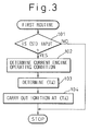
- the ECU 20 controls the ignition time, according to a first routine shown in figure 3.
- the first routine is carried out every predetermined period, and is explained as follows.
- step 101 it is determined whether or not a signal (S1) for starting the engine cranking is input from the ignition switch 34. When the determination is negative, the routine is stopped. On the other hand, when the determination is affirmative, the routine goes to step 102 and a current engine operating condition is determined on the basis of a current engine speed (N), a current amount of intake air (Q), and a temperature (THW) of the cooling water provided by the sensors 31, 32, 33.
- N current engine speed
- Q current amount of intake air
- TW temperature
- step 104 ignition is carried out at the optimum ignition time (Ti). Thus, ignition is started from a cylinder that carries out an initial compression stroke during the engine cranking.
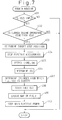
- the ECU 20 controls the fuel injection according to a second routine shown in figure 4.
- the second routine is carried out every predetermined period, and is explained as follows.
- step 201 it is determined whether or not a signal (S1) for starting the engine cranking is input from the ignition switch 34. When the determination is negative, the routine is stopped.
- step 202 it is determined whether or not the preparation for injecting fuel from the fuel injector 8 is finished.
- the preparation include, for example, determining that pressure in the pressure chamber of the fuel injection system has reached a predetermined value which makes the fuel injection possible. When the determination is negative, the routine is stopped.
- a current engine operating condition is determined on the basis of a current engine speed (N), a current amount of intake air (Q), and a temperature (THW) of cooling water provided by the sensors 31, 32, 33.
- N current engine speed
- Q current amount of intake air
- TW temperature
- an optimum fuel injection start time (Ts) during an intake stroke and an optimum amount of fuel injected (THU) for the current engine operating condition are determined from maps (not shown), respectively.
- step 206 fuel injection is carried out on the basis of the optimum fuel injection start time (Ts) and the optimum amount of fuel (THU) or the corrected amount thereof (TAU-TAUK).
- Ts optimum fuel injection start time
- TAU-TAUK corrected amount thereof
- Figure 5 is a third routine for detecting a fuel leak of a fuel injector and identifying the leaking fuel injector through the above-mentioned ignition time control and fuel injection control.
- the routine is carried out at every explosion stroke of each cylinder.
- step 301 it is determined whether or not time (t) which elapses after a signal (S1) for starting the engine cranking is input from the ignition switch 34 is shorter than or equal to a predetermined time (t1).
- t1 time which elapses after a signal (S1) for starting the engine cranking is input from the ignition switch 34 is shorter than or equal to a predetermined time (t1).
- a cylinder in which an initial fuel injection is carried out has not yet completed an explosion stroke after the initial fuel injection was finished, and the routine goes to step 302.
- step 302 it is determined whether or not a difference between a current engine speed (N) and the cranking engine speed (N1) is above a predetermined value (A).
- a flap (F) is reset (0).
- the routine is stopped.
- the determination at step 302 is affirmative, the routine goes to step 304 and thus the flag (F) is set (1).
- step 305 it is determined whether or not a fuel injection was already carried out in a cylinder that is presently in an explosion stroke. When the determination is affirmative, the routine is stopped.
- Each of the count values (C1), (C2), (C3), and (C4) of the respective cylinders is set to (0) when the engine is started for the first time. These count values are not reset even if the engine is stopped.
- step 307 it is determined whether or not the flag (F) is (0).
- the routine is stopped.
- step 308 it is determined that the fuel injector of the cylinder that the first fuel injection is carried out has a fuel leak so that the fuel leak count value (Cn) of this cylinder is increased by one.
- Figure 6 is a time chart from showing the ignition time, fuel injection time, and engine speed, in a start of a manifold-injection-type four-cylinder internal combustion engine. This engine injects fuel during an intake stroke.
- the first to fourth cylinders are ignited in order of #1, #3, #4, and #2.
- the figure shows that the engine is stopped with the first cylinder #1 being in an explosion stroke, the third cylinder #3 in a compression stroke, the fourth cylinder #4 in an intake stroke, and the second cylinder #2 in an exhaust stroke.
- a continuous line in the time chart represents changes in the engine speed in the case that every fuel, injector has no fuel leak.
- the engine is cranked with the cylinders being in the stopped strokes, and in the first cylinder that reaches an intake stroke after the preparedness for fuel injection (after about one turn of the engine cranking) is finished, an initial fuel injection is carried out. Accordingly, an initial explosion occurs in the initial explosion stroke of the first cylinder, and at the same time, the engine speed exceeds the cranking speed. Thereafter, the third, fourth, and second cylinders successively cause an explosion, to gradually increase the engine speed.
- a dot-and-dash line of the time chart represents changes in the engine speed when the second cylinder has a fuel leak.
- no fuel injection is carried out.
- fuel leaked into the intake passage of the second cylinder is drawn into the cylinder with intake air.
- the second cylinder causes an explosion when it is ignited in a compression stroke.
- the engine speed exceeds the cranking speed before the explosion stroke of the first cylinder that the first fuel injection is carried out.
- the determination at step 305 of the third routine is negative, and at step 306, the fuel leak count value (C2) of the second cylinder is increased by one. Namely, it, is determined that the fuel injector of the second cylinder has a fuel leak.
- a two-dot chain line of the time chart represents changes in the engine speed when the first cylinder has a fuel leak.
- fuel leaked into the intake passage as well as injected fuel are drawn into the first cylinder with intake air in an intake stroke just after the start of cranking. Due to this excessive fuel, no explosion occurs even if the cylinder is ignited in the following compression stroke. Accordingly, the flag (F) is remains at (0) without passing the step 304, and therefore, the determination at step 307 is affirmative, and at step 308 the fuel leak count value (C1) of the first cylinder is increased by one. Namely, it is determined that the fuel injector of the first cylinder has a fuel leak.
- a cylinder having a leaking fuel injector in the manifold-injection-type internal combustion engine is stopped in an intake stroke, only a part of the leaked fuel is supplied into the cylinder during the latter half of the intake stroke as soon as the engine is cranked and the amount of fuel supplied is not enough to burn in the cylinder. Accordingly, the unburned fuel can be discharged in an exhaust stroke, to deteriorate the quality of emission.
- a fourth routine of figure 7 can control a fuel cut time when the engine is stopped so that the cylinder in question is not stopped in an intake stroke.
- the fourth routine of Fig. 7 is carried out at intervals of predetermined crank angles.
- step 401 it is determined whether or not a signal (S2) for stopping the engine is input from the ignition switch 34. When the determination is negative, the routine is stopped. On the other hand, when the determination is affirmative, the routine goes to step 402, it is determined whether or not an accelerator pedal is released and a current engine operation is an idle condition. Usually, when a current engine operation is an idle condition, the signal (S2) is input, so that the determination at step 402 is usually affirmative. However, if the determination at step 402 is negative, the routine is repeated until the determination is affirmative. Thereafter, the routine goes to step 403.
- a target stop position of each cylinder is determined, according to the injector which has a fuel leak and any injector which is not yet tested for a fuel leak.
- electric accessories such as an air conditioner, that put load on the engine are stopped.
- a cooling water temperature (THW) is detected, as a value representing an engine friction based on the viscosity of a lubricant, and an engine speed (N) is detected, as a value representing kinetic energy.
- TSW cooling water temperature
- N engine speed
- K an engine revolution angle by the engine stopping after fuel cut is carried out from a given cylinder in the idle engine speed
- step 407 according to the engine revolution angle (K), a cylinder from which the fuel cut is started to realize the target stop position of each cylinder is determined.
- step 408 fuel cut is started from the determined cylinder.
- step 409 the actual engine revolution angle by the engine stopping after fuel cut is carried out from the determined cylinder is detected, and thus according to the actual angle, the map of Fig. 8 is updated.
- step 410 a main electric power is stopped, and the routine is stopped.
- the fuel cut time is delayed after the signal (S2) for stopping the engine is input from the ignition switch, such that the fuel cut is started from the fourth cylinder as shown in a time chart of figure 9.
- the engine revolution angle (K) is about 720 degrees at the maximum.
- a required time to realize the revolution angle (K) is about 0.2 seconds under a usual idling operation, and therefore, the driver will never sense the delay in the engine stop timing.
- the present invention has been explained with reference to the manifold-injection-type internal combustion engine in which a fuel injection is carried out during an intake stroke, the present invention is also applicable to manifold-injection-type internal combustion engines in which a fuel injection is carried out before an intake stroke. Moreover, the present invention is also applicable to a cylinder-injection-type internal combustion engines as shown in figure 10.
- the engine has a fuel injector 8' which is arranged in the cylinder head and injects fuel directly into the combustion chamber 2. Fuel injection of the engine is carried out during an intake stroke or during a compression stroke.
- Figure 11 shows a target stop position of each cylinder to surely burn leaked fuel when any one of fuel injectors leaks fuel in the manifold-injection-type and cylinder-injection-type internal combustion engines.
- the target stop position of one of the first, third, and fourth cylinders will be in an intake stroke. If the fuel injector of the second cylinder of the cylinder-injection-type engine has a fuel leak, the target stop position of the second or first cylinder will be in an intake stroke.
- the target stop position of the second cylinder is set to an intake stroke, to extend a period between the engine cranking start and an ignition time of the second cylinder. If a plurality of the fuel injectors have fuel leaks, the target stop positions of the cylinders are determined to minimize the number of cylinders that discharge unburned leaked fuel.
- the fuel injector of a given cylinder has a fuel leak in the manifold-injection-type internal combustion engine in which a fuel injection is carried out during an intake stroke, if a period between the stoppage and restart of the engine is short, the leak will be small so that the leaked fuel will not burn.
- the stop position of the cylinder in question is set to an explosion or compression stroke, so that fuel injection is carried out as soon as the leaked fuel is supplied into the cylinder in the first intake stroke during the engine cranking.
- the optimum amount of fuel injected (TAU) is corrected at step 205 of the second routine for controlling fuel injection.
- a map of figure 12 is used to estimate an amount of fuel leaked (TAUK) during the engine stoppage and the amount of fuel leaked (TAUK) is subtracted from the optimum amount of fuel injected (TAU) in an initial fuel injection of the fuel injector which has a fuel leak.
- the 12 is set such that the higher the temperature of cooling water (THW) at the start of the engine and the larger the fuel leak count value (Cn) is, the larger the amount of fuel leaked (TAUK) become. Because, the higher the temperature (THW) is, the shorter the time during the engine stoppage is. In connection with the fuel leak count value (Cn), the larger the fuel leak count value (Cn) is, the larger a degree of fuel leak in the fuel injector is. Because, when the fuel leak count value (Cn) is large, a fuel leak of the fuel injector is detected even if the engine stopped period is short.
- the map of Fig. 13 shows a coefficient (a) for correcting the amount of fuel reduced (TAUK) with respect to the number of cycles, i.e., the number of fuel injection operations carried out in a given one of the cylinders. According to this correction, an amount of fuel injected is made (TAU-TAUK*a) in the fuel injector which has a fuel leak.
- TAU-TAUK*a an amount of fuel injected is made (TAU-TAUK*a) in the fuel injector which has a fuel leak.
- step 302 of the third routine it is determined whether or not a given cylinder has caused combustion according to an increase in an engine speed.
- This does not limit the present invention. For example, the amount of intake air suddenly increases when the combustion causes an increase in the engine speed. Accordingly, determining whether or not a cylinder has caused combustion may be made by monitoring the amount of intake air with use of the airflow meter 32 disposed in the intake passage.
- Each cylinder may be provided with a temperature sensor 35 or a vibration sensor 36, as shown in Fig. 2, to directly detect heat or vibration caused by combustion.
- electrodes facing each other and spaced from each other may be arranged in each cylinder, to form one of circuits shown in figures 14 and 15.
- an ion current flows through the circuit.
- Monitoring the ion current by an ammeter 38 may detect the combustion.
- the voltage of the ion current changes in response to an air-fuel ratio as shown in figure 16.
- the voltage of the ion current is detected by a voltmeter 37 and it is possible, therefore, to estimate the amount of leaked fuel according to the air-fuel ratio, to thereby accurately correct a reduction in the amount of injected fuel at the start of the engine.
- the electrodes disposed in each cylinder may be the ignition plug 3.
- a fuel leak in a cylinder is detected by determining whether or not the cylinder has caused combustion without fuel injection, or whether or not the cylinder has caused no combustion even after fuel has been injected.
- ignition must be started from a cylinder that first reaches a compression stroke. To make the latter determination, it is not necessary to start ignition so early.
- a control device for an internal combustion engine comprises a fuel injector provided for each cylinder, an ignition plug starting ignition in each cylinder simultaneously with a start of the engine cranking, and a detection unit for detecting combustion in each cylinder when the engine is started which determines that the fuel injector of a cylinder in which ignition is carried out before fuel injection has a fuel leak when combustion is detected in the cylinder.
Landscapes
- Engineering & Computer Science (AREA)
- Chemical & Material Sciences (AREA)
- Combustion & Propulsion (AREA)
- Mechanical Engineering (AREA)
- General Engineering & Computer Science (AREA)
- Electrical Control Of Air Or Fuel Supplied To Internal-Combustion Engine (AREA)
- Combined Controls Of Internal Combustion Engines (AREA)
Abstract
Description
- The present invention relates to a control device for an internal combustion engine.
- Japanese Unexamined Utility Model Publication No. 3-119551 discloses a control device for a fuel injection system with an injector for injecting fuel directly into the cylinder of an internal combustion engine. This disclosure explains that the fuel injector easily leaks fuel into a cylinder when fuel is not to be injected, i.e., when fuel cut is carried out, because the pressure of fuel in a pressure chamber of the fuel injection system is kept high. To prevent the fuel leak, the control device lowers the fuel pressure in the pressure chamber during a fuel cut. The control device then corrects a fuel injection period directly after the fuel injection is restarted because a fuel pump in the fuel injection system can not quickly increase the lowered fuel pressure to a required level.
- A fuel leak from a fuel injector is caused due to the inaccurate processing of the seat part of the fuel injector, the wear thereof for a long time of use, or the inclusion of a foreign object therein. In all cases, if the fuel leak per unit time is large enough to hinder the operation of the engine, the fuel injector must be replaced. On the other hand, when the fuel leak does not require replacement of the fuel injector, the above-mentioned control device tends to prevent a fuel leak during a fuel cut by lowering the pressure of fuel in the pressure chamber. However, if the fuel injector is designed to improve the sealing of the fuel injection hole by the use of the high fuel pressure in the pressure chamber, the leak will be worsened due to a decrease in the fuel pressure. In such fuel injector, even if the engine is stopped and the fuel pump is stopped and thus the fuel pressure in the pressure chamber becomes equal to an atmospheric pressure, a fuel leak occurs. Accordingly, the above-mentioned control device is incapable of preventing this kind of a fuel leak.
- If the fuel leakage per unit time is small, it will not hinder the operation of the engine. However, once the fuel leakage rises to a certain level during stoppage of the engine, a large part thereof will be unburned and emitted outside when the engine is restarted, to provide a poor-quality emission.
- Moreover, document GB-A-2 273 573 discloses a method for recognizing injection valve leakage, wherein cylinders are monitored into which there is no injection of fuel. These cylinders are subject to ignition during a starting operation after an adequate time of having been turned off is recognized and after synchronization of the engine has taken place. During this starting operation, it is detected whether one or more inflammations take place in these cylinders which are not fed with fuel but which are merely subject to ignition. Normally, the inflammations taken place in the cylinders lead to an increased rotational speed of the engine which is detected by corresponding sensor arrangements so that the evaluation of the detection of the increased rotational speed allows the recognition of inflammations, whereby the rotational speed course is evaluated before and after the first ignitions. If the rotational speed after the first ignitions of the cylinders into which there has been no injection is higher than the speed before the first ignitions, this clearly indicates that additional inflammations have taken place and moreover indicates the existence of leaking injection valves which have supplied the engine cylinders without corresponding injection control.
- Therefore, an object of the present invention is to provide a control device for an internal combustion engine capable of detecting a fuel leak in a fuel injector during a stoppage of the engine and identify the leaking fuel injector.
- According to the present invention, this object is achieved by a control device for an internal combustion engine according to the appended claims.
- The present invention will be more fully understood from the description of preferred embodiments of the invention set forth below, together with the accompanying drawings.
- In the drawings:
- Figure 1 is a sectional view showing a manifold-injection-type internal combustion engine with a control device of the present invention.
- Figure 2 is a schematic view of the ECU in Fig. 1.
- Figure 3 is a first routine for controlling ignition time.
- Figure 4 is a second routine for controlling fuel injection.
- Figure 5 is a third routine for detecting a fuel leak of a fuel injector and identifying the leaking fuel injector.
- Figure 6 is a time chart showing ignition time, fuel injection time, and an engine speed from the engine cranking start.
- Figure 7 is a fourth routine for controlling fuel cut time when the engine is stopped.
- Figure 8 is a map used to determine the engine revolution angle.
- Figure 9 is a time chart showing ignition time, fuel injection time, and an engine speed when the engine is stopped.
- Figure 10 is a sectional view showing a cylinder-injection-type internal combustion engine with a control device of the present invention.
- Figure 11 is a table showing a relationship between a cylinder that has a fuel leak and target stop position of each cylinder.
- Figure 12 is a map used to determine an amount of fuel leaked during a stoppage of the engine.
- Figure 13 is a map used to determine a coefficient for correcting the amount of fuel reduced.
- Figure 14 shows a first circuit for detecting an ion current.
- Figure 15 shows a second circuit for detecting an ion current.
- Figure 16 is a graph showing a relationship between the voltage ratio of an ion current and an air-fuel ratio.
- Figure 1 is a sectional view showing a manifold-injection-type internal combustion engine having a control device according to the present invention. The engine has a
piston 1, acombustion chamber 2, and anignition plug 3 facing thecombustion chamber 2. Anintake passage 5 is connected to thecombustion chamber 2 via anintake valve 4. Anexhaust passage 7 is connected to thecombustion chamber 2 via anexhaust valve 6. Afuel injector 8 is arranged in theintake passage 5 for each cylinder. As is well known, thefuel injector 8 is connected to a pressure chamber of a fuel injection system. -
Reference numeral 20 is an electronic control unit which carries out a fuel injection control via thefuel injector 8, and an ignition time control via theignition plug 3. As shown in figure 2, theECU 20 is constructed as a digital computer and includes a ROM (read only memory) 22, a RAM (random access memory) 23, a CPU (microprocessor, etc.) 24, aninput port 25, and anoutput port 26. TheROM 22, theRAM 23, theCPU 24, theinput port 25, and theoutput port 26 are interconnected by abidirectional bus 21. - An
engine speed sensor 31 for detecting the engine speed is connected to theinput port 25. Anairflow meter 32 for detecting the amount of intake air is connected to theinput port 25, via anAD converter 27a. Atemperature sensor 33 for detecting the temperature of. the cooling water is connected to theinput port 25, via anAD converter 27b. Anignition switch 34 which makes the engine start or stop is connected to theinput port 25, via an AD converter 27c. Thefuel injector 8 is connected to theoutput port 26, via adrive circuit 28a. Theignition plug 3 is connected to the output port, via adrive circuit 28b. - The
ECU 20 controls the ignition time, according to a first routine shown in figure 3. The first routine is carried out every predetermined period, and is explained as follows. First, atstep 101, it is determined whether or not a signal (S1) for starting the engine cranking is input from theignition switch 34. When the determination is negative, the routine is stopped. On the other hand, when the determination is affirmative, the routine goes tostep 102 and a current engine operating condition is determined on the basis of a current engine speed (N), a current amount of intake air (Q), and a temperature (THW) of the cooling water provided by thesensors step 103, an optimum ignition time (Ti) for the current engine operating condition is determined from a map (not shown). Atstep 104, ignition is carried out at the optimum ignition time (Ti). Thus, ignition is started from a cylinder that carries out an initial compression stroke during the engine cranking. - The
ECU 20 controls the fuel injection according to a second routine shown in figure 4. The second routine is carried out every predetermined period, and is explained as follows. First, atstep 201, it is determined whether or not a signal (S1) for starting the engine cranking is input from theignition switch 34. When the determination is negative, the routine is stopped. On the other hand, when the determination is affirmative, the routine goes to step 202 and it is determined whether or not the preparation for injecting fuel from thefuel injector 8 is finished. The preparation include, for example, determining that pressure in the pressure chamber of the fuel injection system has reached a predetermined value which makes the fuel injection possible. When the determination is negative, the routine is stopped. On the other hand, when the determination is affirmative, the routine goes to step 203 and a current engine operating condition is determined on the basis of a current engine speed (N), a current amount of intake air (Q), and a temperature (THW) of cooling water provided by thesensors step 204, an optimum fuel injection start time (Ts) during an intake stroke and an optimum amount of fuel injected (THU) for the current engine operating condition are determined from maps (not shown), respectively. Atstep 205, in connection with the fuel injector which has a fuel leak, the optimum amount of fuel injected (THU) is corrected (
step 206, fuel injection is carried out on the basis of the optimum fuel injection start time (Ts) and the optimum amount of fuel (THU) or the corrected amount thereof (TAU-TAUK). Thus, fuel injection is started from a cylinder that reaches an initial intake stroke after the preparation for fuel injection is finished. - Figure 5 is a third routine for detecting a fuel leak of a fuel injector and identifying the leaking fuel injector through the above-mentioned ignition time control and fuel injection control. The routine is carried out at every explosion stroke of each cylinder. First, at
step 301, it is determined whether or not time (t) which elapses after a signal (S1) for starting the engine cranking is input from theignition switch 34 is shorter than or equal to a predetermined time (t1). When the determination is affirmative, a cylinder in which an initial fuel injection is carried out has not yet completed an explosion stroke after the initial fuel injection was finished, and the routine goes to step 302. - At
step 302, it is determined whether or not a difference between a current engine speed (N) and the cranking engine speed (N1) is above a predetermined value (A). When the determination is negative, the routine goes to step 303 and thus a flap (F) is reset (0). Next, the routine is stopped. On the other hand, when the determination atstep 302 is affirmative, the routine goes to step 304 and thus the flag (F) is set (1). Next, atstep 305, it is determined whether or not a fuel injection was already carried out in a cylinder that is presently in an explosion stroke. When the determination is affirmative, the routine is stopped. On the other hand, when the determination is negative, the routine goes to step 306 and thus it is determined that the fuel injector of this cylinder has a fuel leak so that a fuel leak count value (Cn) (for example, in the case that the engine has four cylinders, n = 1 to 4) of this cylinder is increased by one. Each of the count values (C1), (C2), (C3), and (C4) of the respective cylinders is set to (0) when the engine is started for the first time. These count values are not reset even if the engine is stopped. - Once such flow is repeated and the determination at
step 301 is negative, the routine goes to step 307 and thus it is determined whether or not the flag (F) is (0). When the determination atstep 307 is negative, the routine is stopped. On the other hand, when the determination atstep 307 is affirmative, the routine goes to step 308 and thus it is determined that the fuel injector of the cylinder that the first fuel injection is carried out has a fuel leak so that the fuel leak count value (Cn) of this cylinder is increased by one. - Figure 6 is a time chart from showing the ignition time, fuel injection time, and engine speed, in a start of a manifold-injection-type four-cylinder internal combustion engine. This engine injects fuel during an intake stroke. The first to fourth cylinders are ignited in order of #1, #3, #4, and #2. The figure shows that the engine is stopped with the
first cylinder # 1 being in an explosion stroke, thethird cylinder # 3 in a compression stroke, thefourth cylinder # 4 in an intake stroke, and thesecond cylinder # 2 in an exhaust stroke. - A continuous line in the time chart represents changes in the engine speed in the case that every fuel, injector has no fuel leak. In this case, the engine is cranked with the cylinders being in the stopped strokes, and in the first cylinder that reaches an intake stroke after the preparedness for fuel injection (after about one turn of the engine cranking) is finished, an initial fuel injection is carried out. Accordingly, an initial explosion occurs in the initial explosion stroke of the first cylinder, and at the same time, the engine speed exceeds the cranking speed. Thereafter, the third, fourth, and second cylinders successively cause an explosion, to gradually increase the engine speed.
- On the other hand, a dot-and-dash line of the time chart represents changes in the engine speed when the second cylinder has a fuel leak. In an intake stroke of the second cylinder just after the start of cranking, no fuel injection is carried out. In spite of no fuel injection, fuel leaked into the intake passage of the second cylinder is drawn into the cylinder with intake air. Since ignition is started simultaneously with the start of cranking, the second cylinder causes an explosion when it is ignited in a compression stroke. As a result, the engine speed exceeds the cranking speed before the explosion stroke of the first cylinder that the first fuel injection is carried out. Accordingly, the determination at
step 305 of the third routine is negative, and atstep 306, the fuel leak count value (C2) of the second cylinder is increased by one. Namely, it, is determined that the fuel injector of the second cylinder has a fuel leak. - A two-dot chain line of the time chart represents changes in the engine speed when the first cylinder has a fuel leak. In this case, fuel leaked into the intake passage as well as injected fuel are drawn into the first cylinder with intake air in an intake stroke just after the start of cranking. Due to this excessive fuel, no explosion occurs even if the cylinder is ignited in the following compression stroke. Accordingly, the flag (F) is remains at (0) without passing the
step 304, and therefore, the determination atstep 307 is affirmative, and atstep 308 the fuel leak count value (C1) of the first cylinder is increased by one. Namely, it is determined that the fuel injector of the first cylinder has a fuel leak. - When the cylinders are stopped in the strokes shown in Fig. 6, it is possible to surely detect a fuel leak of the fuel injector of any one of the first and second cylinders. For the other cylinders, they will be stopped in strokes that let a fuel leak be surely detected after the engine is repeatedly stopped and started.
Accordingly, a fuel leak in any one of the cylinders will be detected. - If a cylinder having a leaking fuel injector in the manifold-injection-type internal combustion engine is stopped in an intake stroke, only a part of the leaked fuel is supplied into the cylinder during the latter half of the intake stroke as soon as the engine is cranked and the amount of fuel supplied is not enough to burn in the cylinder. Accordingly, the unburned fuel can be discharged in an exhaust stroke, to deteriorate the quality of emission. To avoid this problem, if the third routine of Fig. 5 detects the fuel leak and the fuel injector having the leaking fuel injector is identified, a fourth routine of figure 7 can control a fuel cut time when the engine is stopped so that the cylinder in question is not stopped in an intake stroke.
- The fourth routine of Fig. 7 is carried out at intervals of predetermined crank angles. At
step 401, it is determined whether or not a signal (S2) for stopping the engine is input from theignition switch 34. When the determination is negative, the routine is stopped. On the other hand, when the determination is affirmative, the routine goes to step 402, it is determined whether or not an accelerator pedal is released and a current engine operation is an idle condition. Usually, when a current engine operation is an idle condition, the signal (S2) is input, so that the determination atstep 402 is usually affirmative. However, if the determination atstep 402 is negative, the routine is repeated until the determination is affirmative. Thereafter, the routine goes to step 403. - At
step 403, a target stop position of each cylinder is determined, according to the injector which has a fuel leak and any injector which is not yet tested for a fuel leak. Next, atstep 404, electric accessories, such as an air conditioner, that put load on the engine are stopped. Atstep 405, a cooling water temperature (THW) is detected, as a value representing an engine friction based on the viscosity of a lubricant, and an engine speed (N) is detected, as a value representing kinetic energy. According to these values, atstep 406, an engine revolution angle (K) by the engine stopping after fuel cut is carried out from a given cylinder in the idle engine speed, is determined from a map figure 8. Next, the routine goes to step 407. - At
step 407, according to the engine revolution angle (K), a cylinder from which the fuel cut is started to realize the target stop position of each cylinder is determined. Atstep 408, fuel cut is started from the determined cylinder. Next, atstep 409, the actual engine revolution angle by the engine stopping after fuel cut is carried out from the determined cylinder is detected, and thus according to the actual angle, the map of Fig. 8 is updated. Atstep 410, a main electric power is stopped, and the routine is stopped. - For example, if it is determined that the fuel injector of the second cylinder has a fuel leak and that the fuel injector of the third cylinder is not yet tested for a fuel leak, it is preferable to stop the third cylinder in an exhaust stroke and the second cylinder in a compression stroke because the target stop position of the second cylinder must be other than an intake stroke. In the case that the engine revolution angle (K) is about 360 degrees on the basis of the above-mentioned values, the fuel cut time is delayed after the signal (S2) for stopping the engine is input from the ignition switch, such that the fuel cut is started from the fourth cylinder as shown in a time chart of figure 9. In a four-cycle engine, the engine revolution angle (K) is about 720 degrees at the maximum. A required time to realize the revolution angle (K) is about 0.2 seconds under a usual idling operation, and therefore, the driver will never sense the delay in the engine stop timing.
- Although the present invention has been explained with reference to the manifold-injection-type internal combustion engine in which a fuel injection is carried out during an intake stroke, the present invention is also applicable to manifold-injection-type internal combustion engines in which a fuel injection is carried out before an intake stroke. Moreover, the present invention is also applicable to a cylinder-injection-type internal combustion engines as shown in figure 10. The engine has a fuel injector 8' which is arranged in the cylinder head and injects fuel directly into the
combustion chamber 2. Fuel injection of the engine is carried out during an intake stroke or during a compression stroke. Figure 11 shows a target stop position of each cylinder to surely burn leaked fuel when any one of fuel injectors leaks fuel in the manifold-injection-type and cylinder-injection-type internal combustion engines. As shown in this figure, if the fuel injector of the second cylinder of the manifold-injection-type engine has a fuel leak, the target stop position of one of the first, third, and fourth cylinders will be in an intake stroke. If the fuel injector of the second cylinder of the cylinder-injection-type engine has a fuel leak, the target stop position of the second or first cylinder will be in an intake stroke. - In the cylinder-injection-type engine, fuel leaks directly into a cylinder. Accordingly, if the second cylinder is in an explosion or exhaust stroke when the engine cranking is started, the leaked fuel will be unburned and discharged from the cylinder. It is preferable to set the target stop position of the second cylinder to an intake stroke, to extend a period between the engine cranking start and an ignition time of the second cylinder. If a plurality of the fuel injectors have fuel leaks, the target stop positions of the cylinders are determined to minimize the number of cylinders that discharge unburned leaked fuel. If three of the fuel injectors have fuel leaks in the cylinder-injection-type engine, the leaked fuel of one of the cylinders will be unburned and discharged from the cylinder. It is preferable to make this cylinder the one having the smallest fuel leak count value (Cn) in the third routine.
- In the case that the fuel injector of a given cylinder has a fuel leak in the manifold-injection-type internal combustion engine in which a fuel injection is carried out during an intake stroke, if a period between the stoppage and restart of the engine is short, the leak will be small so that the leaked fuel will not burn. To prevent this, the stop position of the cylinder in question is set to an explosion or compression stroke, so that fuel injection is carried out as soon as the leaked fuel is supplied into the cylinder in the first intake stroke during the engine cranking.
- In this case, an air-fuel ratio will be too rich if the amount of injected fuel is a usual optimum one determined according to the operating conditions of the engine because the leaked fuel is added to the injected fuel. Therefore, the fuel will not burn, and a large amount of unburned fuel will be discharged. To solve this problem, the optimum amount of fuel injected (TAU) is corrected at
step 205 of the second routine for controlling fuel injection. In this correction, a map of figure 12 is used to estimate an amount of fuel leaked (TAUK) during the engine stoppage and the amount of fuel leaked (TAUK) is subtracted from the optimum amount of fuel injected (TAU) in an initial fuel injection of the fuel injector which has a fuel leak. The map of Fig. 12 is set such that the higher the temperature of cooling water (THW) at the start of the engine and the larger the fuel leak count value (Cn) is, the larger the amount of fuel leaked (TAUK) become. Because, the higher the temperature (THW) is, the shorter the time during the engine stoppage is. In connection with the fuel leak count value (Cn), the larger the fuel leak count value (Cn) is, the larger a degree of fuel leak in the fuel injector is. Because, when the fuel leak count value (Cn) is large, a fuel leak of the fuel injector is detected even if the engine stopped period is short. In any one of the manifold-injection-type and cylinder-injection-type internal combustion engines, leaked fuel adheres to the intake passage or the cylinder, and the adhered fuel will not burn all at once. The remaining fuel is used for the next combustion. Considering this phenomenon, the amount of injected fuel may be gradually brought to an optimum value without suddenly achieving the optimum value in the next combustion. The map of Fig. 13 shows a coefficient (a) for correcting the amount of fuel reduced (TAUK) with respect to the number of cycles, i.e., the number of fuel injection operations carried out in a given one of the cylinders. According to this correction, an amount of fuel injected is made (TAU-TAUK*a) in the fuel injector which has a fuel leak. This technique is also applicable to the cylinder-injection-type internal combustion engine. To surely burn leaked fuel when fuel injection is carried out in an intake stroke, only the first fuel injection operation is delayed up to a compression stroke. - At
step 302 of the third routine, it is determined whether or not a given cylinder has caused combustion according to an increase in an engine speed. This does not limit the present invention. For example, the amount of intake air suddenly increases when the combustion causes an increase in the engine speed. Accordingly, determining whether or not a cylinder has caused combustion may be made by monitoring the amount of intake air with use of theairflow meter 32 disposed in the intake passage. Each cylinder may be provided with atemperature sensor 35 or avibration sensor 36, as shown in Fig. 2, to directly detect heat or vibration caused by combustion. - Alternatively, electrodes facing each other and spaced from each other may be arranged in each cylinder, to form one of circuits shown in figures 14 and 15. As usually known, when combustion occurs, an ion current flows through the circuit. Monitoring the ion current by an
ammeter 38 may detect the combustion. The voltage of the ion current changes in response to an air-fuel ratio as shown in figure 16. The voltage of the ion current is detected by avoltmeter 37 and it is possible, therefore, to estimate the amount of leaked fuel according to the air-fuel ratio, to thereby accurately correct a reduction in the amount of injected fuel at the start of the engine. The electrodes disposed in each cylinder may be theignition plug 3. - In the third routine, a fuel leak in a cylinder is detected by determining whether or not the cylinder has caused combustion without fuel injection, or whether or not the cylinder has caused no combustion even after fuel has been injected. To make the former determination, ignition must be started from a cylinder that first reaches a compression stroke. To make the latter determination, it is not necessary to start ignition so early.
- Although the invention has been described with reference to specific embodiments thereof, it should be apparent that numerous modifications can be made thereto by those skilled in the art, without departing from the basic concept and scope of the invention.
- A control device for an internal combustion engine comprises a fuel injector provided for each cylinder, an ignition plug starting ignition in each cylinder simultaneously with a start of the engine cranking, and a detection unit for detecting combustion in each cylinder when the engine is started which determines that the fuel injector of a cylinder in which ignition is carried out before fuel injection has a fuel leak when combustion is detected in the cylinder.
Claims (6)
- A control device of an internal combustion engine comprising:a fuel injector (8, 8') provided for each cylinder,ignition means (3, 20) for starting ignition in each cylinder simultaneously with a start of the engine cranking,detection means (20, 36) for detecting combustion in each cylinder when the engine is started,determination means (20) for determining that the fuel injector (8, 8') of a cylinder in which ignition is carried out before fuel injection by said ignition means (3, 20) has a fuel leak when said detection means (20, 36) detects combustion in said cylinder, andfuel reducing means (20) for reducing fuel to be injected from the leaking fuel injector determined by said determination means (20) when the engine is started.
- A control device for an internal combustion engine comprising:a fuel injector (8, 8') provided for each cylinder,detection means (20, 36) for detecting combustion in each cylinder when the engine is started,determination means (20) for determining that the fuel injector (8, 8') of a cylinder in which ignition is carried out after fuel injection has a fuel leak when said detection means (20, 36) does not detect combustion in said cylinder, andfuel reduction means (20) for reducing fuel to be injected from the leaking fuel injector determined by said determination means (20) when the engine is started.
- A control device according to claim 1, wherein said fuel reduction means (20) estimates an amount of fuel leaked from the leaking fuel injector during a stoppage of the engine and determines an amount of a fuel reduced according to the amount of a fuel leaked.
- A control device according to claim 2, wherein said fuel reduction means (20) estimates an amount of fuel leaked from the leaking fuel injector during a stoppage of the engine and determines an amount of a fuel reduced according to the amount of fuel leaked.
- A control device according to claim 3, wherein said fuel reduction means (20) estimates an amount of fuel leaked during a stoppage of the engine according to a decrease in the temperature (THW) of cooling water.
- A control device according to claim 4, wherein said fuel reduction means (20) estimates an amount of fuel leaked during a stoppage of the engine according to a decrease in the temperature (THW) of cooling water.
Applications Claiming Priority (5)
| Application Number | Priority Date | Filing Date | Title |
|---|---|---|---|
| JP262854/94 | 1994-10-26 | ||
| JP26285494 | 1994-10-26 | ||
| JP7241702A JPH08177586A (en) | 1994-10-26 | 1995-09-20 | Control device for internal combustion engine |
| JP241702/95 | 1995-09-20 | ||
| EP95116813A EP0709563B1 (en) | 1994-10-26 | 1995-10-25 | Control device for internal combustion engine |
Related Parent Applications (2)
| Application Number | Title | Priority Date | Filing Date |
|---|---|---|---|
| EP95116813.7 Division | 1995-10-25 | ||
| EP95116813A Division EP0709563B1 (en) | 1994-10-26 | 1995-10-25 | Control device for internal combustion engine |
Publications (2)
| Publication Number | Publication Date |
|---|---|
| EP0809007A2 true EP0809007A2 (en) | 1997-11-26 |
| EP0809007A3 EP0809007A3 (en) | 1999-02-03 |
Family
ID=26535402
Family Applications (2)
| Application Number | Title | Priority Date | Filing Date |
|---|---|---|---|
| EP97113898A Withdrawn EP0809007A3 (en) | 1994-10-26 | 1995-10-25 | Control device for internal combustion engine |
| EP95116813A Expired - Lifetime EP0709563B1 (en) | 1994-10-26 | 1995-10-25 | Control device for internal combustion engine |
Family Applications After (1)
| Application Number | Title | Priority Date | Filing Date |
|---|---|---|---|
| EP95116813A Expired - Lifetime EP0709563B1 (en) | 1994-10-26 | 1995-10-25 | Control device for internal combustion engine |
Country Status (4)
| Country | Link |
|---|---|
| US (1) | US5611314A (en) |
| EP (2) | EP0809007A3 (en) |
| JP (1) | JPH08177586A (en) |
| DE (1) | DE69504937T2 (en) |
Families Citing this family (22)
| Publication number | Priority date | Publication date | Assignee | Title |
|---|---|---|---|---|
| US6360161B1 (en) * | 2000-05-04 | 2002-03-19 | Bombardier Motor Corporation Of America | Method and system for fuel injector coefficient installation |
| US6701897B2 (en) * | 2001-02-16 | 2004-03-09 | Optimum Power Technology | Engine fuel delivery management system |
| EP1477654B1 (en) * | 2003-05-16 | 2006-01-04 | Ford Global Technologies, LLC, A subsidary of Ford Motor Company | Method to stop an internal combustion engine at a desired stand-by position |
| KR100588496B1 (en) * | 2003-06-09 | 2006-06-13 | 현대자동차주식회사 | Initial start control device and method of vehicle |
| DE102007021594B4 (en) * | 2007-05-08 | 2016-06-02 | Continental Automotive Gmbh | Method for diagnosing the leakage of an injector and associated control unit |
| JP4835520B2 (en) * | 2007-06-15 | 2011-12-14 | トヨタ自動車株式会社 | Control device for internal combustion engine |
| DE102009045306A1 (en) * | 2009-10-02 | 2011-04-07 | Robert Bosch Gmbh | Method and device for operating an internal combustion engine |
| DE102010062226B4 (en) | 2010-11-30 | 2018-10-25 | Continental Automotive Gmbh | Estimate a leakage fuel quantity of an injection valve during a stop time of a motor vehicle |
| US8267067B2 (en) | 2011-03-08 | 2012-09-18 | Ford Global Technologies, Llc | Method for starting an engine automatically |
| JP5838712B2 (en) * | 2011-10-14 | 2016-01-06 | いすゞ自動車株式会社 | Method for starting engine using dimethyl ether fuel and engine using dimethyl ether fuel |
| JP5821748B2 (en) * | 2012-03-30 | 2015-11-24 | トヨタ自動車株式会社 | Start control device for internal combustion engine |
| JP5821749B2 (en) * | 2012-03-30 | 2015-11-24 | トヨタ自動車株式会社 | Start control device for internal combustion engine |
| JP6191552B2 (en) * | 2014-06-19 | 2017-09-06 | トヨタ自動車株式会社 | Automatic stop control device for internal combustion engine |
| US9663096B2 (en) | 2015-02-20 | 2017-05-30 | Ford Global Technologies, Llc | Methods and systems for mitigating fuel injector leak |
| FR3047275B1 (en) * | 2016-01-29 | 2020-08-14 | Continental Automotive France | MANAGEMENT OF RESIDUAL DROPS ON INJECTORS |
| GB2550599B (en) * | 2016-05-24 | 2020-05-27 | Delphi Tech Ip Ltd | Method of controlling fuel injection test equipment |
| DE102017206416B3 (en) * | 2017-04-13 | 2018-08-02 | Mtu Friedrichshafen Gmbh | Method for determining a permanently injecting combustion chamber, injection system and internal combustion engine with such an injection system |
| CN108318252B (en) * | 2018-01-22 | 2020-06-16 | 哈尔滨工程大学 | Modular water spraying device for humidification test of inlet of gas compressor |
| DE102019212214B3 (en) * | 2019-08-14 | 2020-10-15 | Mtu Friedrichshafen Gmbh | Method for diagnosing an injector leakage in an internal combustion engine, internal combustion engine and computer program product |
| CN114856879B (en) * | 2022-04-11 | 2023-04-07 | 哈尔滨工程大学 | Diesel engine nozzle device capable of being used for combustion state online monitoring and detection method |
| GB2634328A (en) * | 2023-10-06 | 2025-04-09 | Phinia Delphi Luxembourg Sarl | Leakage detection in gas-fuelled power plants |
| GB2636161A (en) * | 2023-12-01 | 2025-06-11 | Phinia Delphi Luxembourg Sarl | Fault detection in gas-fuelled engine systems |
Family Cites Families (13)
| Publication number | Priority date | Publication date | Assignee | Title |
|---|---|---|---|---|
| US4469070A (en) * | 1980-03-12 | 1984-09-04 | Rassey Louis J | Fuel control valve |
| JPS611841A (en) * | 1984-06-12 | 1986-01-07 | Nippon Denso Co Ltd | Fuel injection device for internal-combustion engine |
| JPS6319536A (en) * | 1986-07-14 | 1988-01-27 | Hitachi Ltd | Detector for fine particle in solution |
| JPS63195356A (en) * | 1987-02-06 | 1988-08-12 | Mazda Motor Corp | Fuel feeding device for engine |
| JPH0319445A (en) * | 1989-06-16 | 1991-01-28 | Fujitsu Ltd | Cell synchronization control system |
| JPH03119551A (en) * | 1989-10-02 | 1991-05-21 | Canon Inc | Tape guide device |
| JPH03119551U (en) | 1990-03-22 | 1991-12-10 | ||
| JPH03271538A (en) * | 1990-03-22 | 1991-12-03 | Fuji Heavy Ind Ltd | Fuel injection control device |
| US5020362A (en) * | 1990-06-15 | 1991-06-04 | Hickok Electrical Instrument Company | Fuel injection system tester |
| JPH06137197A (en) * | 1992-09-09 | 1994-05-17 | Nippondenso Co Ltd | Control device for internal combustion engine |
| DE4243178B4 (en) * | 1992-12-19 | 2005-07-14 | Robert Bosch Gmbh | Method for detecting leaky injectors in an internal combustion engine |
| JP2767352B2 (en) * | 1993-02-02 | 1998-06-18 | 株式会社ユニシアジェックス | Air-fuel ratio control device for starting internal combustion engine |
| JP3064748B2 (en) * | 1993-07-14 | 2000-07-12 | 日産自動車株式会社 | Engine fuel control device |
-
1995
- 1995-09-20 JP JP7241702A patent/JPH08177586A/en active Pending
- 1995-10-25 DE DE69504937T patent/DE69504937T2/en not_active Expired - Fee Related
- 1995-10-25 EP EP97113898A patent/EP0809007A3/en not_active Withdrawn
- 1995-10-25 EP EP95116813A patent/EP0709563B1/en not_active Expired - Lifetime
- 1995-10-25 US US08/548,116 patent/US5611314A/en not_active Expired - Fee Related
Also Published As
| Publication number | Publication date |
|---|---|
| EP0709563A1 (en) | 1996-05-01 |
| JPH08177586A (en) | 1996-07-09 |
| DE69504937D1 (en) | 1998-10-29 |
| US5611314A (en) | 1997-03-18 |
| EP0709563B1 (en) | 1998-09-23 |
| DE69504937T2 (en) | 1999-04-29 |
| EP0809007A3 (en) | 1999-02-03 |
Similar Documents
| Publication | Publication Date | Title |
|---|---|---|
| EP0709563B1 (en) | Control device for internal combustion engine | |
| US5808189A (en) | Failure diagnosis controller of pressure sensor | |
| US6732707B2 (en) | Control system and method for internal combustion engine | |
| US20150120172A1 (en) | Spark plug degradation detection | |
| US7603994B2 (en) | Abnormality diagnosis device and control system for internal combustion engine | |
| US4492203A (en) | Fuel supply control method for an internal combustion engine equipped with a supercharger, having a fail-safe function for abnormality in intake passage pressure sensor means | |
| US5881552A (en) | Control system for internal combustion engines and control system for vehicles | |
| US5690075A (en) | Method of and apparatus for controlling fuel injection in internal combustion engine | |
| US5927248A (en) | Method of monitoring an overheating protective arrangement during full-load operation of an internal combustion engine | |
| US7167794B2 (en) | Control apparatus for an internal combustion engine | |
| US7128053B2 (en) | Control apparatus for internal combustion engine | |
| US5546905A (en) | Control apparatus for controlling the ignition timing of an internal combustion engine | |
| US7085671B2 (en) | Abnormality detection apparatus of engine temperature adjusting thermostat | |
| CN101680376A (en) | Starter for internal-combustion engine | |
| CN100560964C (en) | Method for determination of smoldering in internal combustion engines | |
| JP2000230453A (en) | Temperature sensor failure diagnosis device | |
| EP0176359B1 (en) | Fuel supply control method for multicylinder internal combustion engines during occurrence of abnormality in engine rotational angle position sensing means | |
| US6684153B2 (en) | Fuel nature judging device for internal combustion engine | |
| US4502448A (en) | Method for controlling control systems for internal combustion engines immediately after termination of fuel cut | |
| JP3972604B2 (en) | In-cylinder direct injection internal combustion engine fuel system diagnostic device | |
| JPH0263097B2 (en) | ||
| EP1321668A1 (en) | Apparatus for detecting abnormality of glow plugs | |
| JP2008280865A (en) | Start control device for internal combustion engine | |
| EP1416146B1 (en) | Internal combustion engine output control device | |
| US7104046B2 (en) | Controller for an internal combustion engine |
Legal Events
| Date | Code | Title | Description |
|---|---|---|---|
| PUAI | Public reference made under article 153(3) epc to a published international application that has entered the european phase |
Free format text: ORIGINAL CODE: 0009012 |
|
| AC | Divisional application: reference to earlier application |
Ref document number: 709563 Country of ref document: EP |
|
| AK | Designated contracting states |
Kind code of ref document: A2 Designated state(s): DE FR GB |
|
| PUAL | Search report despatched |
Free format text: ORIGINAL CODE: 0009013 |
|
| AK | Designated contracting states |
Kind code of ref document: A3 Designated state(s): DE FR GB |
|
| STAA | Information on the status of an ep patent application or granted ep patent |
Free format text: STATUS: THE APPLICATION IS DEEMED TO BE WITHDRAWN |
|
| 18D | Application deemed to be withdrawn |
Effective date: 19990804 |