EP0808964A2 - Tensioning device for flooring to be laid floatingly - Google Patents
Tensioning device for flooring to be laid floatingly Download PDFInfo
- Publication number
- EP0808964A2 EP0808964A2 EP97107348A EP97107348A EP0808964A2 EP 0808964 A2 EP0808964 A2 EP 0808964A2 EP 97107348 A EP97107348 A EP 97107348A EP 97107348 A EP97107348 A EP 97107348A EP 0808964 A2 EP0808964 A2 EP 0808964A2
- Authority
- EP
- European Patent Office
- Prior art keywords
- rod
- rod section
- pressure
- section
- length
- Prior art date
- Legal status (The legal status is an assumption and is not a legal conclusion. Google has not performed a legal analysis and makes no representation as to the accuracy of the status listed.)
- Withdrawn
Links
Images


Classifications
-
- E—FIXED CONSTRUCTIONS
- E04—BUILDING
- E04F—FINISHING WORK ON BUILDINGS, e.g. STAIRS, FLOORS
- E04F21/00—Implements for finishing work on buildings
- E04F21/20—Implements for finishing work on buildings for laying flooring
- E04F21/22—Implements for finishing work on buildings for laying flooring of single elements, e.g. flooring cramps ; flexible webs
Definitions
- the invention relates to a tensioning device for floating flooring such as laminates and finished parquet, with pressure jaws arranged at the two ends of a length-adjustable, multi-part rod for compressing a plurality of strip-shaped flooring panels to be joined together by means of tongue and groove.
- a tensioning device for floating flooring such as laminates and finished parquet
- pressure jaws arranged at the two ends of a length-adjustable, multi-part rod for compressing a plurality of strip-shaped flooring panels to be joined together by means of tongue and groove.
- Laminates and finished parquet differ in material thickness as well as in format, are also dimensioned differently by the various manufacturers with regard to the external dimensions as well as tongue and groove and consist of a carrier material and a surface layer made of other wood, which when used the clamping devices must not be damaged. Also, the tongue to be inserted into the groove of a subsequent plate at the edge of the plate must not be deformed by the pressure exerted by a tensioning device, because it would then no longer be possible to produce a clean plate connection.
- the present invention was therefore based on the object of providing a tensioning device suitable for the floating laying of flooring tiles, the pressure jaws of which only apply pressure against the substrate material when laying flooring tiles of different formats of different manufacturers and when laying thicker laminates or thicker finished parquet , whereby the length-adjustable rod connecting the two pressure jaws always lies fully on the top of each of the different types of material in the material thickness, so that when pressure is exerted on the side edges of, for example, three rows of plates, these cannot bulge in the middle.
- the object of the invention was further to very precisely the pressure to be exerted when laying flooring tiles of different formats, i.e. to be able to adjust continuously.
- the tensioning device has the features according to claims 1 and 2.
- the tensioning device has a multi-part, length-adjustable rod 1, the first rod section 2 of which is smaller in cross section than the longer one second rod section 3, in which the rod section 2 can be telescopically pushed in and pushed out.
- a flat plate 4 is welded on as a pressure jaw, which has edge strips 5 and 6 projecting horizontally on two mutually parallel edges. These consist of the bent edges of the plate 4, but could also be separately applied strips.
- the edge strips 5 and 6 have a different vertical distance from the rod section 2, so that the tensioning device can be used for laying laminates as well as for finished parquet, which is thicker in material thickness than the former.
- the edge strip 5 of the pressure jaw 4 lies below the spring 8 against the carrier material of the flooring plate made of laminate, as can be seen from FIG. 1.
- the bar section 2, which is rectangular in cross section, can be used after separation from the bar section 3 and rotation through 180 ° in the manner described above for the finished parquet 9, which is thicker in material thickness, as shown in FIG. 4. Due to this configuration, the wear layer visible after laying on the carrier material and the tongue and groove are never damaged.
- the multi-part rod 1 is always fully on the flooring slabs so that when pressure is exerted against, for example, three rows of flooring slabs joined against one another, these cannot bulge upward as a result of the pressure.
- the pressure jaw 10 is at a short distance from the wall on which the laying work begins.
- the rod section 2 with the pressure jaw 4 can also be easily exchanged for a different-format pressure jaw.
- a tensioning force is exerted on the tensioning device by means of a tensioning lever 12 which is mounted on the second, longer rod section 3 so as to be pivotable about an axis of rotation 13.
- a stepless length adjustment of the rod 1 is provided in the form of a movement screw consisting of a threaded sleeve 14 and a threaded bolt 15, which is connected to the tensioning lever 12 by means of a pivot axis 16.
- the end of the threaded bolt 15 of the motion screw is connected to a coupling piece 18 via a pivot axis 17.
- This coupling piece 18 can be firmly connected to the first rod section 2, for example connected by means of a screw 19 which is screwed into one of a series of threaded bores 20 which are spaced apart from one another in the first rod section 2 on the upper side.
- the pivot axis 17 between the coupling piece 18 and the movement screw 14, 15 is necessary because the movement screw also pivots upward during the pivoting movement of the tensioning lever 12, as can be seen from FIG. 3.
- the tensioning position is reached when the over-center position of the tensioning lever 12 is reached, when it lies completely on the rod 1.
Landscapes
- Engineering & Computer Science (AREA)
- Architecture (AREA)
- Civil Engineering (AREA)
- Structural Engineering (AREA)
- Floor Finish (AREA)
Abstract
Die Spannvorrichtung für schwimmend zu verlegenden Bodenbelag wie Laminate und Fertigparkett dient zum Gegeneinanderdrücken einer Anzahl mittels Nut und Feder ineinanderfügbarer streifenförmiger Bodenbelagsplatten. An den Enden einer längenverstellbaren, mehrteiligen Stange (1) sind Druckbacken (4, 10) angeordnet. Horizontal einwärts vorstehende Randleisten (5,6,) an der einen Druckbacke (4) drücken ausschliesslich gegen das Trägermaterial der Bodenbelagsplatte an,unter Schonung von Nutzschicht und Feder (8) der Bodenbelagsplatte.
Da Laminate und Fertigparkett eine unterschiedliche Materialdicke aufweisen, ist der Abstand der an der Druckbacke (4) vorstehenden Randleisten (5,6) von dem die Druckbacke tragenden ersten Stangenabschnitt (2) unterschiedlich gross und kann dieser aus dem zweiten Stangenabschnitt (3) herausziehbare Stangenabschnitt (2) nach Drehung um 180° und wieder Zusammenfügen zum Verlegen in der Materialstärke verschieden dicker Bodenbelagsplatten verwendet werden. Für die einstellbar feste Verbindung der teleskopartig ineinander schiebbaren beiden Stangenabschnitte (2,3) und zum Spannen dient ein auf dem Stangenabschnitt (3) angeordneter Spannhebel (12) und eine an diesen anschliessende, aus Gewindehülse (14) und Gewindebolzen (15) bestehende Bewegungsschraube für die stufenlose Längenverstellung der Spannvorrichtung durch Betätigung dieser Bewegungsschraube, sowie ein an diese anschliessendes Kupplungsstück (18), das mit dem ersten Stangenabschnitt (2) verschraubbar ist und zwecks stufenweiser Längenverstellung längs des eine Anzahl von Gewindebohrungen (20) aufweisenden ersten Stangenabschnitts (2) versetzt und verschraubt werden kann.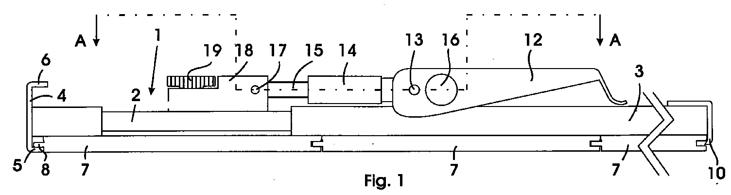
Since laminates and finished parquet have a different material thickness, the distance between the edge strips (5, 6) projecting from the pressure jaw (4) is different in size from the first bar section (2) carrying the pressure jaw, and the bar section can be pulled out of the second bar section (3) (2) after rotation by 180 ° and reassembling for laying in the material thickness of different thickness flooring slabs are used. A tensioning lever (12) arranged on the rod section (3) and a moving screw consisting of a threaded sleeve (14) and threaded bolt (15) are used for the adjustable, fixed connection of the two rod sections (2, 3) which can be telescopically pushed into one another for the stepless length adjustment of the tensioning device by actuating this movement screw, as well as a coupling piece (18) adjoining it, which can be screwed to the first rod section (2) and for the purpose of stepwise length adjustment along the first rod section (2) having a number of threaded bores (20) can be moved and screwed.
Description
Die Erfindung betrifft eine Spannvorrichtung für schwimmend zu verlegenden Bodenbelag wie Laminate und Fertigparkett, mit an den beiden Enden einer längenverstellbaren, mehrteiligen Stange angeordneten Druckbacken zum Zusammendrücken mehrerer parallel mittels Nut und Feder ineinander zu fügender streifenförmiger Bodenbelagsplatten.
Bei schwimmend verlegten Bodenbelägen, die aus Laminaten oder Fertigparkett bestehen, wird keine vollflächige Verleimung mit dem Boden sondern nur eine Verleimung der in der Regel zwei Meter langen streifenförmigen Bodenbelagsplatten an der Nut- und Federverbindung zwischen den Platten durchgeführt. Wenn diese Klebverbindung nicht schon in den ersten Reihen einer ganzen Zimmerbodenfläche sehr genau erfolgt, addieren sich einzelne Fehler zu einem am Ende nicht tollerierbaren Verlegeergebnis, so dass ein sauberer Anschluss an die dem Verlegebeginn gegenüber liegende Zimmerwand ausgeschlossen sein kann. Darum werden beim Verlegen der ersten Reihen eine Anzahl gleicher Spannvorrichtungen im Abstand voneinander eingesetzt, mit deren Hilfe die Plattenreihen mit nicht zu starkem und nicht zu schwachem Druck gegeneinander gepresst werden. Laminate und Fertigparkett unterscheiden sich in der Materialstärke wie auch im Format, sind ausserdem von den verschiedenen Herstellern bezüglich der Aussenabmessungen wie auch der Nut und Feder unterschiedlich bemasst und bestehen aus einem Trägermaterial und einer aus anderem Holz bestehenden, die Oberfläche bildenden Nutzschicht, die bei Einsatz der Spannvorrichtungen nicht beschädigt werden darf. Auch die in die Nut einer anschliessenden Platte einzufügende Feder am Plattenrand darf durch die Druckausübung einer Spannvorrichtung nicht verformt werden, weil die Herstellung einer sauberen Plattenverbindung dann nicht mehr möglich wäre.The invention relates to a tensioning device for floating flooring such as laminates and finished parquet, with pressure jaws arranged at the two ends of a length-adjustable, multi-part rod for compressing a plurality of strip-shaped flooring panels to be joined together by means of tongue and groove.
In the case of floating floor coverings consisting of laminates or finished parquet, no full-surface gluing to the floor is carried out, but only the generally two-meter-long strip-shaped floor covering panels are glued to the tongue and groove connection between the panels. If this adhesive connection is not made very precisely in the first rows of an entire room floor area, individual errors add up to an installation result that cannot be tolerated at the end, so that a clean connection to the room wall opposite the start of installation can be excluded. Therefore, when laying the first rows, a number of identical clamping devices are used at a distance from one another, with the aid of which the rows of plates are pressed against one another with pressure that is not too strong and not too weak. Laminates and finished parquet differ in material thickness as well as in format, are also dimensioned differently by the various manufacturers with regard to the external dimensions as well as tongue and groove and consist of a carrier material and a surface layer made of other wood, which when used the clamping devices must not be damaged. Also, the tongue to be inserted into the groove of a subsequent plate at the edge of the plate must not be deformed by the pressure exerted by a tensioning device, because it would then no longer be possible to produce a clean plate connection.
Bei bekannten Spannvorrichtungen dieser Art ist die schonende Druckausübung gegen die Ränder der Bodenbelagsplatten nicht gewährleistet, weil die vorzugsweise aus Gusseisen bestehenden Druckbacken der bekannten Spannvorrichtungen nicht ausschliesslich nur gegen das Träger material der Bodenbelagsplatten andrücken. Ausserdem ist es von Nach teil, wenn bei verschieden formatigen Bodenbelagsplatten die dafür notwendige Längenverstellung der Spannvorrichtung nur in Stufen erfolgen kann, weil der ausgeübte Druck dann zu gross oder zu klein ist.In known clamping devices of this type, gentle pressure is exerted against the edges of the flooring plates not guaranteed, because the pressure jaws, which are preferably made of cast iron, of the known clamping devices do not only press against the carrier material of the flooring plates. In addition, it is of part if the length adjustment of the tensioning device required for differently sized flooring slabs can only be done in stages because the pressure exerted is then too large or too small.
Der vorliegenden Erfindung lag daher die Aufgabe zugrunde, eine für die schwimmende Verlegung von Bodenbelagsplatten geeignete Spannvorrichtung zu schaffen, deren Druckbacken beim Verlegen von unterschiedlich formatigen Bodenbelagsplatten verschiedener Hersteller sowie beim Verlegen von in der Materialstärke dünneren Laminaten oder dickerem Fertigparkett ausschliesslich nur gegen das Trägermaterial Druck ausüben, wobei die die beiden Druckbacken verbindende längenverstellbare Stange bei jeder der in der Materialstärke verschiedenen Plattenarten immer auf deren Oberseite voll aufliegt, damit sich bei Druckausübung auf die Seitenränder von beispielsweise drei Plattenreihen diese sich nicht in der Mitte hochwölben können. Die Aufgabe der Erfindung bestand weiterhin darin, den auszuübenden Druck beim Verlegen von Bodenbelagsplatten verschiedener Formate sehr genau, d.h. stufenlos einstellen zu können. Zur Lösung der ganannten Aufgaben weist die Spannvorrichtung die Merkmale nach den Ansprüchen 1 und 2 auf.The present invention was therefore based on the object of providing a tensioning device suitable for the floating laying of flooring tiles, the pressure jaws of which only apply pressure against the substrate material when laying flooring tiles of different formats of different manufacturers and when laying thicker laminates or thicker finished parquet , whereby the length-adjustable rod connecting the two pressure jaws always lies fully on the top of each of the different types of material in the material thickness, so that when pressure is exerted on the side edges of, for example, three rows of plates, these cannot bulge in the middle. The object of the invention was further to very precisely the pressure to be exerted when laying flooring tiles of different formats, i.e. to be able to adjust continuously. To solve the above-mentioned tasks, the tensioning device has the features according to
Ein Ausführungsbeispiel des Erfindungsgegenstandes wird nachfolgend anhand der Zeichnungen näher erläutert. Es zeigen:
- Fig.1 eine Seitenansicht der Spannvorrichtung, auf drei Bodenbelagsplatten aufliegend;
- Fig.2. eine Draufsicht auf die Vorrichtung, teilweise im Horizontalschnitt gemäss der Linie A-A in Fig. 1;
- Fig.3 die Spannvorrichtung gemäss Fig. 1, mit hochgeschwenktem Spannhebel;
- Fig.4 einen Längsschnitt durch die Spannvorrichtung gemäss der Linie B-B in Fig.2.
- 1 shows a side view of the tensioning device, lying on three flooring panels;
- Fig. 2. a plan view of the device, partly in horizontal section along the line AA in Fig. 1;
- 3 the tensioning device according to FIG. 1, with the tensioning lever pivoted up;
- 4 shows a longitudinal section through the clamping device along the line BB in Figure 2.
Die Spannvorrichtung weist eine mehrteilige, längenverstellbare Stange 1 auf, deren erster Stangenabschnitt 2 im Querschnitt kleiner ist als der längere zweite Stangenabschnitt 3, in welchen der Stangenabschnitt 2 teleskopartig ein- und ausschiebbar ist. Am Ende des ersten Stangenabschnitts 2 ist als Druckbacke eine flache Platte 4 angeschweisst, die an zwei zueinander parallelen Rändern horizontal vorstehende Randleisten 5 und 6 aufweist Diese bestehen aus den umgebogenen Rändern der Platte 4, könnten aber auch separat aufgesetzte Leisten sein.The tensioning device has a multi-part, length-adjustable rod 1, the
Die Randleisten 5 und 6 haben einen unterschiedlichen senkrechten Abstand von dem Stangenabschnitt 2, damit die Spannvorrichtung für das Verlegen von Laminaten wie auch für Fertigparkett verwendet werden kann, welches gegenüber ersterem in der Materialstärke dicker ist. Bei dem Laminat 7 liegt die Randleiste 5 der Druckbacke 4 unterhalb der Feder 8 gegen das Trägermaterial der aus Laminat bestehenden Bodenbelagsplatte an, wie aus Fig. 1 hervorgeht. Der im Querschnitt rechteckförmige Stangenabschnitt 2 lässt sich nach Trennung von dem Stangenabschnitt 3 und Drehen um 180° in der zuvor beschriebenen Weise für das in der Materialstärke dickere Fertigparkett 9 verwenden, wie in Fig. 4 dargestellt ist. Aufgrund dieser Ausgestaltung wird die nach der Verlegung sichtbare Nutzschicht auf dem Trägermaterial wie auch die Nut und Feder nie beschädigt. Bei dieser Ausgestaltung und Anwendung liegt auch die mehrteilige Stange 1 immer voll auf den Bodenbelagsplatten auf, damit sich bei Druckausübung gegen beispielsweise drei gegeneinander gefügte Reihen von Bodenbelagsplatten diese sich nicht infolge des Drucks nach oben wölben können. Am gegenüber liegenden Ende der Spannvorrichtung befindet sich die Druckbacke 10 in geringem Abstand von der Wand an, an welcher die Verlegearbeit beginnt. Der Stangenabschnitt 2 mit der Druckbacke 4 lässt sich auch leicht gegen eine andersformatige Druckkbacke auswechseln.The
Für die Druckausübung auf die Bodenbelagsplatten wird an der Spannvorrichtung eine Spannkraft mittels eines Spannhebels 12 ausgeübt, der am zweiten längeren Stangenabschnitt 3 um eine Drehachse 13 schwenkbar gelagert ist. Um den genau erforderlichen Druck ausüben zu können, ist eine stufenlose Längenverstellung der Stange 1 in Form einer aus einer Gewindehülse 14 und einem Gewindebolzen 15 bestehenden Bewegungsschraube vorgesehen, die an den Spannhebel 12 mittels einer Schwenkachse 16 angeschlossen ist. Durch Drehen der Gewindehülse 14 verändert sich die Länge der Bewegungsschraube, wodurch eine Längenverstellung der mehrteiligen Stange 1 im Millimeterbereich zur Einstellung der erforderlichen Druckkraft erreichbar ist.To exert pressure on the floor covering panels, a tensioning force is exerted on the tensioning device by means of a
Das Ende des Gewindebolzens 15 der Bewegungsschraube ist über eine Schwenkachse 17 mit einem Kupplungsstück 18 verbunden. Dieses Kupplungsstück 18 ist mit dem ersten Stangenabschnitt 2 fest verbindbar, beispielsweise mittels einer Schraube 19 verbunden, die in eine von einer Reihe Gewindebohrungen 20 eingeschraubt ist, welche im Abstand voneinander in dem ersten Stangenabschnitt 2 oberseitig angeordnet sind. Dadurch ist eine stufenweise Veränderung der Länge der Stange 1 möglich, wenn die Spannvorrichtung für verschieden formatige Platten eingesetzt werden soll. Die Schwenkachse 17 zwischen den Kupplungsstück 18 und der Bewegungsschraube 14,15 ist erforderlich, weil die Bewegungsschraube bei der Schwenkbewegung des Spannhebels 12 ebenfalls nach oben schwenkt, wie aus Fig. 3 hervorgeht. Die Spannnstellung ist bei Erreichen der Uebertotpunktlage des Spannhebels 12 erreicht, wenn dieser auf der Stange 1 ganz aufliegt.The end of the threaded
Claims (5)
Applications Claiming Priority (2)
| Application Number | Priority Date | Filing Date | Title |
|---|---|---|---|
| CH1263/96 | 1996-05-20 | ||
| CH126396 | 1996-05-20 |
Publications (2)
| Publication Number | Publication Date |
|---|---|
| EP0808964A2 true EP0808964A2 (en) | 1997-11-26 |
| EP0808964A3 EP0808964A3 (en) | 1998-03-25 |
Family
ID=4206312
Family Applications (1)
| Application Number | Title | Priority Date | Filing Date |
|---|---|---|---|
| EP97107348A Withdrawn EP0808964A3 (en) | 1996-05-20 | 1997-05-03 | Tensioning device for flooring to be laid floatingly |
Country Status (2)
| Country | Link |
|---|---|
| US (1) | US5788221A (en) |
| EP (1) | EP0808964A3 (en) |
Cited By (4)
| Publication number | Priority date | Publication date | Assignee | Title |
|---|---|---|---|---|
| WO2006012706A1 (en) * | 2004-08-05 | 2006-02-09 | Paul Maxwell Travis Gaunt | Floor tool |
| WO2009052796A3 (en) * | 2007-10-24 | 2009-07-30 | Braun & Wuerfele Gmbh & Co | Device for laying planks, for example for terrace coverings |
| EP2562326A1 (en) * | 2011-08-25 | 2013-02-27 | SPAX International GmbH & Co. KG | Help device for aligning floor boards when laying hardwood floors |
| CN110872903A (en) * | 2019-12-02 | 2020-03-10 | 广东博智林机器人有限公司 | Floor side knocking device and floor mounting robot |
Families Citing this family (11)
| Publication number | Priority date | Publication date | Assignee | Title |
|---|---|---|---|---|
| CH691866A5 (en) * | 1997-01-06 | 2001-11-15 | Profloor Technology Gmbh | Pressure jaw for a clamping device for a floating floor covering to be laid. |
| US5971361A (en) * | 1997-04-17 | 1999-10-26 | Heimbach; Jacob C. | Clampless laminate flooring tool |
| US6079182A (en) * | 1997-11-05 | 2000-06-27 | Ellenberger; Jack Richard | Floor panel compressing apparatus and method |
| US6370836B1 (en) | 2000-08-24 | 2002-04-16 | Dalen Eugene Gunn | Floor board compression apparatus |
| USD485477S1 (en) | 2002-08-13 | 2004-01-20 | Garland Jerome Gaskins | Deck board straightener |
| US6669173B1 (en) | 2002-09-27 | 2003-12-30 | James R. Dunn | Dual purpose pneumatic floor covering device |
| US20070022845A1 (en) * | 2005-06-22 | 2007-02-01 | Andre Lee-Rodrigues | Heavy duty pull bar |
| US7886785B2 (en) * | 2007-02-15 | 2011-02-15 | Julius Young | Machine and method for installing curved hardwood flooring |
| US8434738B1 (en) | 2010-09-13 | 2013-05-07 | Powernail Company | Flooring installation tool |
| DE202011051107U1 (en) * | 2011-08-25 | 2011-11-08 | Spax International Gmbh & Co. Kg | Auxiliary device for aligning floorboards when laying floor boards |
| US20260022570A1 (en) * | 2024-07-16 | 2026-01-22 | Omg Building Products Llc | Hidden Clip for Grooved Building Members |
Family Cites Families (7)
| Publication number | Priority date | Publication date | Assignee | Title |
|---|---|---|---|---|
| US975566A (en) * | 1909-12-18 | 1910-11-15 | Frank Norton | Floor-set. |
| US1781833A (en) * | 1925-04-24 | 1930-11-18 | Cummer Freeman Baker | Siding clamp |
| US3779515A (en) * | 1972-03-09 | 1973-12-18 | D Larios | Adjustable decking and framing tool |
| US4620691A (en) * | 1985-05-16 | 1986-11-04 | Waters Jr Lloyd E | Board straightening device |
| FR2682978B1 (en) * | 1991-10-23 | 1998-08-07 | Bernard Legeai | DEVICE FOR POSITIONING SLABS USED IN THE BUILDING. |
| DE4304992A1 (en) * | 1992-02-18 | 1993-09-30 | Volker Born | Clamping device for boards - incorporates tensioning tie bar which connects two opposing jaws either side of boards. |
| DE9320608U1 (en) * | 1993-07-21 | 1994-10-20 | Schulte, Johannes, 59602 Rüthen | Device for laying a finished parquet or laminar floor |
-
1997
- 1997-05-03 EP EP97107348A patent/EP0808964A3/en not_active Withdrawn
- 1997-05-16 US US08/857,304 patent/US5788221A/en not_active Expired - Fee Related
Cited By (5)
| Publication number | Priority date | Publication date | Assignee | Title |
|---|---|---|---|---|
| WO2006012706A1 (en) * | 2004-08-05 | 2006-02-09 | Paul Maxwell Travis Gaunt | Floor tool |
| US7913976B2 (en) | 2004-08-05 | 2011-03-29 | Paul Maxwell Travis Gaunt | Floor tool assembly |
| WO2009052796A3 (en) * | 2007-10-24 | 2009-07-30 | Braun & Wuerfele Gmbh & Co | Device for laying planks, for example for terrace coverings |
| EP2562326A1 (en) * | 2011-08-25 | 2013-02-27 | SPAX International GmbH & Co. KG | Help device for aligning floor boards when laying hardwood floors |
| CN110872903A (en) * | 2019-12-02 | 2020-03-10 | 广东博智林机器人有限公司 | Floor side knocking device and floor mounting robot |
Also Published As
| Publication number | Publication date |
|---|---|
| US5788221A (en) | 1998-08-04 |
| EP0808964A3 (en) | 1998-03-25 |
Similar Documents
| Publication | Publication Date | Title |
|---|---|---|
| DE69413391T3 (en) | CONNECTION SYSTEM FOR FLOOR PLATES | |
| EP0808964A2 (en) | Tensioning device for flooring to be laid floatingly | |
| DE102008046476B4 (en) | Laying device for laying curbs | |
| DE102008018072B3 (en) | Boards shifting device for e.g. terrace covering, has outer frame part assigned to traction-longitudinal unit i.e. pull rod, where pressure/traction plate is arranged on outer end of traction-longitudinal unit as outer flanges | |
| DE4100327C2 (en) | Device for fastening a ski binding on a ski | |
| DE19945279C1 (en) | Device and method for producing floor panels and panels manufactured in accordance with the method | |
| DE3529877C1 (en) | Apparatus for bridging expansion joints | |
| DE60223678T2 (en) | DEVICE FOR DISTRIBUTING ADHESIVE MATERIAL | |
| DE102004029879A1 (en) | Panels with border especially for walls and ceilings | |
| DE4304992A1 (en) | Clamping device for boards - incorporates tensioning tie bar which connects two opposing jaws either side of boards. | |
| EP3839370A1 (en) | Device for fastening solar panels | |
| EP0619406B1 (en) | Clamping wedge for laying parquet planks | |
| DE69804569T2 (en) | Automatic screen printing system | |
| EP0577136B1 (en) | Apparatus for applying glue | |
| CH691866A5 (en) | Pressure jaw for a clamping device for a floating floor covering to be laid. | |
| AT515860B1 (en) | Arrangement and connecting body | |
| DE9413838U1 (en) | Device for releasable connection of abutting floor panels of a removable sports or multi-purpose hall floor | |
| DE102021001805A1 (en) | Pressing device for pressing workpieces made of wood, plastic, metal and the like | |
| DE3219151A1 (en) | Clamping device | |
| EP4215673B1 (en) | Levelling screed for a screeding structure of a sidewalk, small and area paver | |
| DE3517306A1 (en) | Device for aligning shuttering elements arranged next to one another | |
| EP0859103B1 (en) | Pressure jaw for a tensioning system | |
| DE2809584A1 (en) | Clamp for assembling mitred picture frame joint - has spring loaded serrated slider held by bolted support plate | |
| DE4442367C1 (en) | Plasterboard fitting aid for building work | |
| EP1630312B1 (en) | Wall connector |
Legal Events
| Date | Code | Title | Description |
|---|---|---|---|
| PUAI | Public reference made under article 153(3) epc to a published international application that has entered the european phase |
Free format text: ORIGINAL CODE: 0009012 |
|
| AK | Designated contracting states |
Kind code of ref document: A2 Designated state(s): AT CH DE FR GB LI SE |
|
| PUAL | Search report despatched |
Free format text: ORIGINAL CODE: 0009013 |
|
| AK | Designated contracting states |
Kind code of ref document: A3 Designated state(s): AT CH DE FR GB LI SE |
|
| 17P | Request for examination filed |
Effective date: 19980402 |
|
| 17Q | First examination report despatched |
Effective date: 19991020 |
|
| GRAG | Despatch of communication of intention to grant |
Free format text: ORIGINAL CODE: EPIDOS AGRA |
|
| GRAG | Despatch of communication of intention to grant |
Free format text: ORIGINAL CODE: EPIDOS AGRA |
|
| GRAH | Despatch of communication of intention to grant a patent |
Free format text: ORIGINAL CODE: EPIDOS IGRA |
|
| STAA | Information on the status of an ep patent application or granted ep patent |
Free format text: STATUS: THE APPLICATION IS DEEMED TO BE WITHDRAWN |
|
| 18D | Application deemed to be withdrawn |
Effective date: 20010118 |