EP0808408B1 - Apparatus for providing a slidingly-separable connection between a movable barrier and a means for guiding the barrier - Google Patents
Apparatus for providing a slidingly-separable connection between a movable barrier and a means for guiding the barrier Download PDFInfo
- Publication number
- EP0808408B1 EP0808408B1 EP96907045A EP96907045A EP0808408B1 EP 0808408 B1 EP0808408 B1 EP 0808408B1 EP 96907045 A EP96907045 A EP 96907045A EP 96907045 A EP96907045 A EP 96907045A EP 0808408 B1 EP0808408 B1 EP 0808408B1
- Authority
- EP
- European Patent Office
- Prior art keywords
- receptacle
- connecting member
- lateral connecting
- barrier
- block
- Prior art date
- Legal status (The legal status is an assumption and is not a legal conclusion. Google has not performed a legal analysis and makes no representation as to the accuracy of the status listed.)
- Expired - Lifetime
Links
- 230000004888 barrier function Effects 0.000 title claims abstract description 44
- 230000033001 locomotion Effects 0.000 description 12
- 238000000926 separation method Methods 0.000 description 8
- 230000007246 mechanism Effects 0.000 description 5
- 125000006850 spacer group Chemical group 0.000 description 2
- 229910000831 Steel Inorganic materials 0.000 description 1
- 230000001419 dependent effect Effects 0.000 description 1
- 239000002783 friction material Substances 0.000 description 1
- 230000003116 impacting effect Effects 0.000 description 1
- 238000004519 manufacturing process Methods 0.000 description 1
- 230000004048 modification Effects 0.000 description 1
- 238000012986 modification Methods 0.000 description 1
- 239000004033 plastic Substances 0.000 description 1
- 230000009467 reduction Effects 0.000 description 1
- 230000004044 response Effects 0.000 description 1
- 230000000087 stabilizing effect Effects 0.000 description 1
- 239000010959 steel Substances 0.000 description 1
Images


Classifications
-
- E—FIXED CONSTRUCTIONS
- E06—DOORS, WINDOWS, SHUTTERS, OR ROLLER BLINDS IN GENERAL; LADDERS
- E06B—FIXED OR MOVABLE CLOSURES FOR OPENINGS IN BUILDINGS, VEHICLES, FENCES OR LIKE ENCLOSURES IN GENERAL, e.g. DOORS, WINDOWS, BLINDS, GATES
- E06B9/00—Screening or protective devices for wall or similar openings, with or without operating or securing mechanisms; Closures of similar construction
- E06B9/56—Operating, guiding or securing devices or arrangements for roll-type closures; Spring drums; Tape drums; Counterweighting arrangements therefor
- E06B9/58—Guiding devices
-
- E—FIXED CONSTRUCTIONS
- E06—DOORS, WINDOWS, SHUTTERS, OR ROLLER BLINDS IN GENERAL; LADDERS
- E06B—FIXED OR MOVABLE CLOSURES FOR OPENINGS IN BUILDINGS, VEHICLES, FENCES OR LIKE ENCLOSURES IN GENERAL, e.g. DOORS, WINDOWS, BLINDS, GATES
- E06B9/00—Screening or protective devices for wall or similar openings, with or without operating or securing mechanisms; Closures of similar construction
- E06B9/56—Operating, guiding or securing devices or arrangements for roll-type closures; Spring drums; Tape drums; Counterweighting arrangements therefor
- E06B9/58—Guiding devices
- E06B9/581—Means to prevent or induce disengagement of shutter from side rails
-
- E—FIXED CONSTRUCTIONS
- E06—DOORS, WINDOWS, SHUTTERS, OR ROLLER BLINDS IN GENERAL; LADDERS
- E06B—FIXED OR MOVABLE CLOSURES FOR OPENINGS IN BUILDINGS, VEHICLES, FENCES OR LIKE ENCLOSURES IN GENERAL, e.g. DOORS, WINDOWS, BLINDS, GATES
- E06B9/00—Screening or protective devices for wall or similar openings, with or without operating or securing mechanisms; Closures of similar construction
- E06B9/56—Operating, guiding or securing devices or arrangements for roll-type closures; Spring drums; Tape drums; Counterweighting arrangements therefor
- E06B9/58—Guiding devices
- E06B2009/585—Emergency release to prevent damage of shutter or guiding device
Definitions
- the present invention relates generally to movable barriers, such as flexible roll-up curtain doors or panel doors, which can be opened by accumulating the door overhead, and more particularly to a slidingly-separable connection between a movable barrier and its associated jambs or guides.
- movable barriers such as flexible roll doors
- separable connections between the barrier and the means for guiding the barrier within the confines of the opening.
- the separable connection is provided to minimize damage in the event of an impact on the barrier, such as by a service vehicle.
- the separable connections of Mueller and subsequently others operate on the principle that the connections are slidingly separable.
- a first member attached to a guide mechanism in the door jambs extends toward the barrier and a portion thereof is cooperatively fitted into a receptacle-type structure in the barrier.
- this receptacle is fcrmed in a rigid leading edge of the barrier, commonly referred to as a bottom bar of the barrier.
- the guide follower separates and the barrier is allowed to move transversely of the opening without damage to the door or to the guide followers.
- Such systems have found widespread use and have been found to significantly reduce the damage to overhead doors caused by unintended impacts, as, for example, with a moving forklift.
- the bottom bar of the movable barrier becomes rotated.
- the bottom bar may also be forced into a translational motion in a direction which, while generally transverse to the plane of the barrier, is not 90° with respect to the plane of the barrier.
- upper and lower surfaces within the receptacle can jamb or bind on upper and lower surfaces of the first member. This can cause a substantial increase in the amount of force required for separation of the two components. In extreme cases, the resistance will so far exceed the desired predetermined separation force as to cause damage to the movable barrier and possibly to the guide means and associated apparatus.
- the present invention provides an apparatus for connecting a movable barrier to a means for guiding the barrier during operation to selectively block an opening.
- the connection separates upon a transbarrier impact in excess of a predetermined magnitude.
- the second end of the lateral connecting member generally defines other than rectangle.
- the second end of the lateral connecting member can generally define a square cross-section or a horizontally-extending circular or oval-shaped cylinder with flat upper and lower outer surfaces.
- FIG. 1 discloses a roll-up door 10, which includes opposed side jambs 11, a flexible curtain 12, a drum 14, a rigid leading edge for the curtain 12 in the form of a bottom bar 16, a guide 18 at each side of the curtain 12 for guiding it during opening and closing and for stabilizing the door in its closed position, and a tension mechanism 20 in each jamb 11 for providing a constant tension on the guides 18 for added control and stiffness of the flexible curtain 12.
- the flexible curtain 12 is rolled up and down on drum 14, while the guides 18 maintain the curtain 12 in a uniform path.
- the bottom bar 16 of the flexible curtain 12 is connected to the guide 18 through a laterally-extending lateral connecting member 22, which cooperatively is received in receptacle 24 of the bottom bar 16.
- the tension mechanism 20 is such as disclosed in U.S. Patent No. 4,997,022, the disclosure of which will be understood by those in the art:.
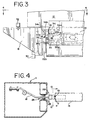
- the guide 18 follows a vertical slot 26 in the jambs 11, as best disclosed in FIG. 4.
- Spacers 28 are provided on both sides of guide 18 within the slot 26.
- the spacers 28 are manufactured from a low-friction material to reduce wear and to assist in smooth and uniform opening and closing of the flexible curtain 12.
- a rubber foot 30 on a lower portion of guide 18 is provided to limit the extent to which the door can be closed against a threshold. The rubber foot 30 also reduces impact from the door as it closes rapidly.
- Rubber foot 32 on an upper portion of the guide 18 provides a similar function for when the door is rolled to its uppermost position, providing a shock-absorbing positive stop.
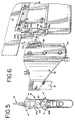
- FIG. 6 best discloses how the lateral connecting member 22 and the receptacle 24 appear after a separation due to a force of magnitude in excess of a predetermined amount.
- FIG. 3 shows the inner connection of the lateral connecting member 22 and the receptacle 24.
- FIGS. 3 and 6 disclose that receptacle 24, in this embodiment, is comprised of an upper block 34 and a lower block 36.
- a portion 34a of upper block 34 is recessed into the bottom bar 16, while a portion 34b of block 34 extends beyond an end of the bottom bar 16.
- Lower block 36 has a portion 36a, which is recessed into the bottom bar 16, and a portion 36b extends beyond the end of the bottom bar.
- a portion 34c of upper block 34 depends from a terminal end of portion 34b, creating a space 34d between portion 34c and the portion 34a of upper block 34.
- the extending portion 36b of lower block 36 and the extending portions 34b and 34c of upper block 34 define receptacle 24.
- Receptacle 24 receives the lateral connecting member 22, in a manner which will be described in more detail below.
- lateral connecting member 22 has a first end 22a connected to guide 18, and a second end, which extends into the receptacle 24 and defines a vertical elongate rectangular portion or shoe 22b.
- An extended base portion 22c of lateral connecting member 22 depends from first end 22a.
- portions 22a, 22b and 22c are formed as an integral piece of steel.
- the depending portion 22c is preferably welded to the guide member 18.
- a slot 19 in side face 17 of shoe 22b cooperates with a springloaded ball 13 loaded on an inside surface of the end of bottom bar 16 within the receptacle 24.
- this slot 19 and ball 13 are employed to help align and hold the shoe 22b in the receptacle during reassembly.
- Tension system 20 pulls the shoe 22b into depending portion 34c during normal operation, which stabilizes the interconnection by lateral and frictional forces.
- a permanent magnet 38 is cooperatively and magnetically coupled with reed-type magnetic sensor 40 to detect when the shoe 22b is separated from receptacle 24, so as to stop an electric motor (not shown) from continuing to open or close the flexible curtain 12 upon impact.
- portion 36b of lower block 36 has an upward-facing surface 42.
- Portion 34b of upper block 34 has a downward-facing surface 44.
- Shoe 22b has an upward-facing upper surface 46 and an opposed downward-facing lower outer surface 48.
- the surfaces 42, 44, 46 and 48 are those of most significant interest during impacts on the bottom bar 16, which cause the bottom bar to rotate in a manner, such as shown by arrows A in FIG. 5.
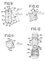
- FIGS. 7-11 schematically disclose various situations and configurations with respect to sliding separation between a receptacle and a shoe, such as shoe 22b, during impact and rotation.
- FIG. 7 discloses a cross-section of a shoe 50, having an upper outer surface 52 and a lower outer surface 54.
- a receptacle 60 is shown schematically having an inner upper surface 62 and a inner lower surface 64.
- the shoe 50 of FIG. 7 has a height H1 between its upper and lower outer surfaces 52, 54.
- FIG. 7A discloses the configuration of FIG. 7 in a condition where the receptacle 60 has rotated to an angle A, which is approximately 20° to the horizontal.
- the receptacle continues in translational movement in a direction along arrow V1
- the shoe 50 will clear the upper and lower receptacle surfaces 60, 64 without contact.
- the height H1 of the second end portion 50 is limited, such that H1 is less than the shortest vertical distance D between the upper inner surface 62 and the lower inner surface 64.
- FIG. 8 discloses a second end of a lateral connecting member or shoe 70 having a height H2 which is greater than H1 of the shoe 50.
- the receptacle 60 remains the same as in FIG. 7. As can be seen in FIG. 7, as can be seen in FIG.
- FIG. 9 discloses receptacle 60 with a shoe 80. While the height of shoe 80 is H2, it is believed that it will accommodate translational movement of the receptacle in a direction along either V1 or V2 without binding.
- the shoe 80 is of identical height to the shoe 70; however, after rotation of receptacle 60, if the receptacle 60 continues in a translational motion along a direction of arrow V1, its upper surface 62 will collide or engage an arcuate portion 84 of upper surface 82 of the shoe 80. Because the surface 84 is arcuate, minimal interference will take place.
- the tension applied to the guide 18 by the tensioning system 20 allows for some vertical play in the shoe 80. Specifically, the tension is applied by strap 21 to an end of guide 18, as shown in FIG. 6.
- the guide 18 acts as a long lever arm, which results in a rotational force, causing the shoe 22b to be urged upward in the direction of arrow B of FIGS.
- the embodiment shown schematically in FIG. 9 provides acceptable results where the impact force may cause a translational movement of receptacle 60 in any angle of directions between V1 and V2. It will be understood that, if one desires to accommodate a lesser angle, the dimensions, such as H2, may be increased and still obtain acceptable results. It will also be noted that the provision of the arcuate surface 84 reduces the maximum or greatest distance between upper and lower surfaces of shoe 80 because of the reduction of the diagonal extreme. This will permit increasing the height beyond H2, if desired. However, the limitation still applies that the greatest distance between any point on upper surface 82 and any point on lower surface 90 can be no greater than the smallest distance between any point on the upper inner surface 62 and the lower inner surface 64 of receptacle 60.
- FIG. 10 discloses a shoe 100, according to the principals discussed above, in a separating situation from a receptacle 110.
- the receptacle 110 and shoe 100 are of the same width dimensions as the embodiments disclosed in FIGS. 7-9 and it is believed that acceptable results may also be provided where, as with receptacle 110, the upper inner surface 112 thereof terminates in arcuate portions 114 and 116.
- the principles discussed above also apply to shoes of any cross-sectional shape, which present upper outer surfaces and lower outer surfaces and are employed with a receptacle which provides upper and lower inner surfaces.
- FIG. 11 discloses a shoe 120 having a generally cylindrical cross-section with blunted or flat upper outer surface 122 and flat lower outer surface 124.
- shoe 22b of lateral connecting member 22 and receptacle 24 is similar to the schematic configuration of FIG. 9. It is believed that the shoe 22b and receptacle 24 employ the principles discussed with regard to the configuration disclosed in FIG. 9.
- the shoe 22b is of a height and diagonal dimension selected for a range of rotation of receptacle 24, which is expected to be encountered for the configuration.
- the shoe has opposed sides 47 and 45 of preselected width dimension relative to the receptacle 24.
- the upper outer surface includes portions 46a and 46b connecting it with sides 45 and 47, respectively.
- the lower outer surface 48 includes arcuate portions 48a and 48b to connect it with sides 45 and 47, respectively.
- a friction plastic seat 43 is interposed between the lower inner surface 42 and the lower outer surface 48 to reduce noise, wear and friction during separation. As disclosed in FIG. 3, such low friction pads are also employed on various side surfaces within the receptacle to reduce noise, wear and friction, both during normal operation and during a separation due to impact.
Landscapes
- Structural Engineering (AREA)
- Engineering & Computer Science (AREA)
- Architecture (AREA)
- Civil Engineering (AREA)
- Input Circuits Of Receivers And Coupling Of Receivers And Audio Equipment (AREA)
- Operating, Guiding And Securing Of Roll- Type Closing Members (AREA)
- Power-Operated Mechanisms For Wings (AREA)
- Feeding And Controlling Fuel (AREA)
- Pivots And Pivotal Connections (AREA)
- Slide Fasteners (AREA)
- Refuge Islands, Traffic Blockers, Or Guard Fence (AREA)
- Cable Accessories (AREA)
- Purses, Travelling Bags, Baskets, Or Suitcases (AREA)
- Joining Of Building Structures In Genera (AREA)
- Vibration Dampers (AREA)
- Specific Sealing Or Ventilating Devices For Doors And Windows (AREA)
- Buildings Adapted To Withstand Abnormal External Influences (AREA)
- Devices Affording Protection Of Roads Or Walls For Sound Insulation (AREA)
- Closing And Opening Devices For Wings, And Checks For Wings (AREA)
- Preliminary Treatment Of Fibers (AREA)
- Footwear And Its Accessory, Manufacturing Method And Apparatuses (AREA)
Abstract
Description
Claims (16)
- An apparatus for connecting a movable barrier (12) to a means for guiding the barrier during operation to selectively block an opening, the connection separating upon impact in excess of a predetermined magnitude, comprising:a connecting member (22) attached to one of either the means for guiding the barrier or the movable barrier (12) and adapted to be received by a receptacle (24), the receptacle (24) being attached to the other of the means for guiding the barrier or the movable barrier (12);the apparatus being characterised in that the connecting member extends laterally and has opposed first (22a) and second (22b) ends, the first end (22a) being attached to one of either the means for guiding the barrier or the movable barrier, and the receptacle is adapted to receive the second end (22b) of the lateral connecting member (22); whereinthe lateral connecting member (22) and the receptacle (24) are cooperatively dimensioned so that, over a predetermined range of accommodatable relative rotation between the receptacle (24) and the lateral connecting member (22), the rotation being in a plane other than the plane of the barrier (12), the connecting member (22) and the receptacle (24) are separable upon impact in excess of a predetermined magnitude.
- An apparatus according to Claim 1,the second end (22b) of the lateral connecting member (22) having generally opposed upper (46) and lower (48) outer surfaces;the receptacle (24) having generally facing, upper (44) and lower (42) inner surfaces; andthe lateral connecting member (22) and the receptacle (24) being cooperatively dimensioned so that, over a predetermined range of relative rotation between the receptacle (24) and the said second end (22b) of the lateral connecting member (22), a smallest vertical distance between any point on the upper inner surface (44) and any point on the lower inner surface (42) of the receptacle (24) being no less after rotation than the height between the upper outer surface (46) and the lower outer surface (48) of the second end (22b) of the lateral connecting member (22).
- An apparatus according to Claim 1, wherein:the second end (22b) of the lateral connecting member (22) having generally opposed upper (46) and lower (48) outer surfaces;the receptacle (24) having generally facing, upper (44) and lower (42) inner surfaces; and,the lateral connecting member (22) and the receptacle (24) being cooperatively dimensioned so that, over a predetermined range of relative rotation between the receptacle (24) and the second end (22b) of the lateral connecting member (22), a greatest distance between any point on the upper outer surface (46) and any point on the lower outer surface (48) of the second end of the lateral connecting member (22) being no greater than the smallest distance between any point on the upper inner surface (44) and any point on the lower inner surface (42) of the receptacle (24).
- An apparatus according to Claim 3, wherein the upper (44, 112) and lower (42) inner surfaces of the receptacle (24, 110) terminate in upwardly directed arcuate portions (114, 116).
- An apparatus according to Claims 3 or 4 wherein:
the opposed upper (46) and lower (48) outer surfaces are spaced by side surfaces (45, 47) and the upper (46) and lower (48) outer surfaces include arcuate portions (46a, 46b, 48a, 48b) connecting with the side surfaces (45, 47). - An apparatus according to Claims 4 or 5, wherein the second end (22b) of the lateral connecting member (22) is an elongate vertical rectangle.
- An apparatus according to Claims 4 or 5, wherein the second end (22b) of the lateral connecting member (22) has a square cross section.
- An apparatus according to Claims 4 or 5, wherein the second end (22b) of the lateral connecting member (22) generally defines a horizontally extending circular cylinder.
- An apparatus according to any one of Claims 1 to 8, wherein a slot (19) is provided in a side face (17) of the second end (22b) of the lateral connecting member (22) and a spring loaded ball (13) is loaded against a surface (16) of the movable barrier, wherein the the slot (19) and ball (13) co-operate to assist in holding the lateral connecting member (22) in the receptacle (24).
- An apparatus according to Claim 1 wherein the receptacle (24) comprises:a first block (34) having first, second and third portions (34a, 34b, 34c), the first portion (34a) being on one of the means for guiding the barrier or the movable barrier (12), the second portion (34b) being adjacent the first portion (34a) and extending beyond an end of the other of the means for guiding the barrier or the movable barrier (12), and the third portion (34c) extending from the second portion (34b); anda second block (36) having first and second portions (36a, 36b), the first portion (36a) of the second block (36) being on the other of the means for guiding the barrier or the movable barrier (12), and the second portion (36b) of the second block (36) being adjacent the first portion (36a) of the second block (36) and extending beyond an end of the other of the means for guiding the barrier or the movable barrier (12).
- An apparatus according to Claim 12 wherein the first block (34) is an upper block, the second block (36) is a lower block positioned below the upper block, and the third portion (34c) of the first block (34) depends from the second portion (34b) of the first block (34) toward the lower block.
- The apparatus according to any one of Claims 1 to 11 wherein the second end (22b) of the lateral connecting member (22) defines a shoe adjacent to the first end (22a) of the lateral connecting member (22), and the receptacle (24) is adapted to receive the shoe.
- The apparatus of Claim 12 wherein the shoe is elongate and has a vertical orientation.
- The apparatus of Claim 13 wherein the shoe extends above the first end (22a) of the lateral connecting member (22).
- The apparatus according to any one of Claims 1 to 14 wherein the lateral connecting member (22) includes a base portion which extends from the first end (22a) of the lateral connecting member (22) and is on one of either the means for guiding the barrier or the movable barrier (12).
- An apparatus according to any one of Claims 1 to 15 wherein the predetermined range of accommodatable relative rotation between the receptacle (24) and the lateral connecting member (22) is from 0° up to about 20°.
Applications Claiming Priority (3)
| Application Number | Priority Date | Filing Date | Title |
|---|---|---|---|
| US387411 | 1995-02-10 | ||
| US08/387,411 US5620039A (en) | 1995-02-10 | 1995-02-10 | Apparatus for providing a slidingly-separable connection between a movable barrier and a means for guiding the barrier |
| PCT/US1996/001879 WO1996024743A1 (en) | 1995-02-10 | 1996-02-12 | Apparatus for providing a slidingly-separable connection between a movable barrier and a means for guiding the barrier |
Publications (2)
| Publication Number | Publication Date |
|---|---|
| EP0808408A1 EP0808408A1 (en) | 1997-11-26 |
| EP0808408B1 true EP0808408B1 (en) | 2001-08-29 |
Family
ID=23529757
Family Applications (1)
| Application Number | Title | Priority Date | Filing Date |
|---|---|---|---|
| EP96907045A Expired - Lifetime EP0808408B1 (en) | 1995-02-10 | 1996-02-12 | Apparatus for providing a slidingly-separable connection between a movable barrier and a means for guiding the barrier |
Country Status (11)
| Country | Link |
|---|---|
| US (1) | US5620039A (en) |
| EP (1) | EP0808408B1 (en) |
| JP (1) | JP3556673B2 (en) |
| KR (1) | KR100414257B1 (en) |
| CN (1) | CN1117206C (en) |
| AT (1) | ATE204946T1 (en) |
| AU (1) | AU5022896A (en) |
| BR (1) | BR9607585A (en) |
| DE (2) | DE808408T1 (en) |
| SI (1) | SI9620025B (en) |
| WO (1) | WO1996024743A1 (en) |
Families Citing this family (26)
| Publication number | Priority date | Publication date | Assignee | Title |
|---|---|---|---|---|
| US5535805A (en) | 1994-02-18 | 1996-07-16 | Hpd International, Inc. | Overhead door |
| DK171579B1 (en) * | 1995-01-18 | 1997-01-27 | Rasmussen Kann Ind As | End-stop mechanism for an electrically operated window guard device |
| US6089305A (en) * | 1995-02-10 | 2000-07-18 | Rite-Hite Holding Corporation | Curtain guiding assembly for a soft edge door with a selectively tensioned leading edge |
| FR2762349B1 (en) * | 1997-04-16 | 1999-05-21 | Nergeco Sa | SECURITY DOOR WITH SLIDING PANEL |
| CA2288652A1 (en) * | 1997-04-16 | 1998-10-22 | Nergeco | Security door with sliding panel |
| DE29716966U1 (en) | 1997-09-22 | 1997-11-13 | Schieffer Tor- und Schutzsysteme GmbH, 59557 Lippstadt | Roller door with a flexible door leaf |
| US6039106A (en) * | 1998-01-09 | 2000-03-21 | Albany International Corp. | Door with articulated cam |
| DE29906582U1 (en) * | 1999-04-14 | 2000-09-21 | Langenbach, Guido, 37191 Katlenburg-Lindau | Crash protection device |
| US6508292B1 (en) * | 2000-03-29 | 2003-01-21 | Fivent, S.A. | Retractable mosquito net |
| EP1191184A1 (en) * | 2000-09-25 | 2002-03-27 | Dynaco International | Shutter device for closing an opening |
| US6688374B2 (en) * | 2001-11-09 | 2004-02-10 | Rite-Hite Holding Corporation | Barrier with movable curtain |
| BE1016275A3 (en) * | 2002-06-13 | 2006-07-04 | Dynaco International Sa | Dipositif a component of a drum roll around. |
| US6942003B2 (en) * | 2003-07-25 | 2005-09-13 | Service Door Industries Limited | Roll-up door curtain and guides and bottom bar therefor |
| US8371357B2 (en) * | 2006-02-06 | 2013-02-12 | Assa Abloy Entrance Systems Ab | System to guide the slats of an industrial roller door to reduce damages after crash |
| JP4247751B2 (en) * | 2006-08-10 | 2009-04-02 | トヨタ紡織株式会社 | Sunshade equipment |
| FR2905721B1 (en) * | 2006-09-13 | 2011-03-04 | Dirickx Groupe | GUIDING DEVICE FOR PORTAL |
| US8037576B2 (en) * | 2007-08-16 | 2011-10-18 | 4Front Engineered Solutions, Inc. | Overhead doors and associated track and guide assemblies for use with same |
| US7900683B2 (en) * | 2008-01-18 | 2011-03-08 | Salvatore Michael Decola | Systems for bracing garage doors against hurricane force winds |
| DE102010020693A1 (en) * | 2010-05-17 | 2011-11-17 | Troodon Torsysteme Gmbh | Gate for closing an opening in a wall |
| US8832996B2 (en) * | 2010-10-05 | 2014-09-16 | Miller Edge, Inc. | Sensing edge |
| US10246927B2 (en) * | 2010-10-05 | 2019-04-02 | Miller Edge, Inc. | Sensing edge |
| EP2439368A3 (en) * | 2010-10-05 | 2014-07-23 | Miller Edge, Inc. | Resistor storage cavity in plug of sensing edge |
| US9074414B1 (en) * | 2011-04-06 | 2015-07-07 | John Steffi | Roll up guard curtain |
| US8893764B2 (en) | 2012-08-08 | 2014-11-25 | 4Front Engineered Solutions, Inc. | Overhead door decelerators and associated devices, systems, and methods |
| DE102012111611A1 (en) * | 2012-11-29 | 2014-06-05 | Efaflex Inzeniring D.O.O. | Roller shutter with a door leaf in the form of a flexible curtain |
| FR3081835B1 (en) * | 2018-06-05 | 2021-04-09 | Zodiac Seats France | SEATING ARRANGEMENT, ESPECIALLY OF AN AIRCRAFT |
Family Cites Families (23)
| Publication number | Priority date | Publication date | Assignee | Title |
|---|---|---|---|---|
| US1033224A (en) * | 1911-03-04 | 1912-07-23 | Raymond Andlauer | Curtain-fixture. |
| US1922389A (en) * | 1932-01-12 | 1933-08-15 | Harry B Lawson | Curtain fixture |
| GB563606A (en) * | 1943-04-15 | 1944-08-22 | John Howard Cooper | Improvements in door or like catches |
| FR966811A (en) * | 1948-05-05 | 1950-10-19 | Reciprocating stopper | |
| DE1619920B1 (en) * | 1967-09-27 | 1970-10-01 | Siemens Ag | Swirl device for pre-cleaning the raw gas flow of a three-phase vortex |
| US3797553A (en) * | 1972-07-17 | 1974-03-19 | P Elliott | Selective positioning means for curtain assembly |
| SE386944B (en) * | 1972-08-18 | 1976-08-23 | Nordiska Maskinfilt Ab | RULLJALUSIPORT |
| US3981343A (en) * | 1974-09-23 | 1976-09-21 | Arthur M. Brady | Counterbalancing mechanism for rolling doors |
| US4036517A (en) * | 1975-05-14 | 1977-07-19 | Talmadge Samuel I | Rotary door latch |
| US4478268B1 (en) * | 1980-12-29 | 1991-04-23 | Door structure | |
| US4676293A (en) * | 1983-03-18 | 1987-06-30 | Frommelt Industries, Inc. | Impact-resistant overhead door |
| CA1260025A (en) * | 1985-11-14 | 1989-09-26 | M & I Door Systems Limited | Apparatus for opening and closing industrial door |
| US4800946A (en) * | 1986-05-27 | 1989-01-31 | Frommelt Industries, Inc. | Windstrap for pliable roll-type overhead door |
| US4711505A (en) * | 1987-02-06 | 1987-12-08 | Lakso Matthew L | Locking system |
| FR2624190B1 (en) * | 1987-12-02 | 1990-05-11 | Nergeco Sa | REINFORCEMENT AND GUIDANCE BAR FOR A FLEXIBLE CURTAIN WITH VERTICAL LIFTING DOOR |
| US5141043A (en) * | 1989-05-19 | 1992-08-25 | Nergeco Sa | Lifting curtain door |
| US5048588A (en) * | 1989-06-26 | 1991-09-17 | Kelley Company Inc. | Roll-up door construction |
| US5025847A (en) * | 1989-06-27 | 1991-06-25 | Rytec Corporation | Apparatus for accommodating application of a force in excess of a predetermined magnitude and closure employing such apparatus |
| US5141044A (en) * | 1991-01-25 | 1992-08-25 | Asi Technologies, Inc. | Breakaway roll-up door |
| US5139074A (en) * | 1991-04-03 | 1992-08-18 | Kelley Company Inc. | Industrial door having flexible and releasable beam |
| US5139075A (en) * | 1991-05-31 | 1992-08-18 | Eddy Desrochers | Operator for a rolling door assembly |
| US5222541A (en) * | 1992-07-22 | 1993-06-29 | Kelley Company, Inc. | Industrial door having releasable beam and tension bracket retention mechanism |
| US5271448A (en) * | 1992-07-27 | 1993-12-21 | Rytec Corporation | Movable barrier with two part guide follower |
-
1995
- 1995-02-10 US US08/387,411 patent/US5620039A/en not_active Expired - Lifetime
-
1996
- 1996-02-12 AT AT96907045T patent/ATE204946T1/en not_active IP Right Cessation
- 1996-02-12 SI SI9620025A patent/SI9620025B/en not_active IP Right Cessation
- 1996-02-12 WO PCT/US1996/001879 patent/WO1996024743A1/en not_active Ceased
- 1996-02-12 DE DE0808408T patent/DE808408T1/en active Pending
- 1996-02-12 AU AU50228/96A patent/AU5022896A/en not_active Abandoned
- 1996-02-12 BR BR9607585A patent/BR9607585A/en not_active IP Right Cessation
- 1996-02-12 KR KR1019970705537A patent/KR100414257B1/en not_active Expired - Fee Related
- 1996-02-12 JP JP52447996A patent/JP3556673B2/en not_active Expired - Lifetime
- 1996-02-12 EP EP96907045A patent/EP0808408B1/en not_active Expired - Lifetime
- 1996-02-12 CN CN96192507A patent/CN1117206C/en not_active Expired - Lifetime
- 1996-02-12 DE DE69614826T patent/DE69614826T2/en not_active Expired - Lifetime
Also Published As
| Publication number | Publication date |
|---|---|
| WO1996024743A1 (en) | 1996-08-15 |
| BR9607585A (en) | 1998-12-15 |
| KR100414257B1 (en) | 2004-04-29 |
| KR19980702142A (en) | 1998-07-15 |
| EP0808408A1 (en) | 1997-11-26 |
| DE69614826D1 (en) | 2001-10-04 |
| DE808408T1 (en) | 1998-06-25 |
| CN1178568A (en) | 1998-04-08 |
| HK1015431A1 (en) | 1999-10-15 |
| SI9620025B (en) | 1999-12-31 |
| SI9620025A (en) | 1998-02-28 |
| AU5022896A (en) | 1996-08-27 |
| JPH11504686A (en) | 1999-04-27 |
| JP3556673B2 (en) | 2004-08-18 |
| ATE204946T1 (en) | 2001-09-15 |
| US5620039A (en) | 1997-04-15 |
| DE69614826T2 (en) | 2002-04-04 |
| CN1117206C (en) | 2003-08-06 |
Similar Documents
| Publication | Publication Date | Title |
|---|---|---|
| US5620039A (en) | Apparatus for providing a slidingly-separable connection between a movable barrier and a means for guiding the barrier | |
| KR100831102B1 (en) | Damping device | |
| JP7094011B2 (en) | Sliding door bounce prevention device | |
| JP2001507418A (en) | Cable-type window lifter with guide rail | |
| KR101192049B1 (en) | Floor lock | |
| JP4875875B2 (en) | Door closing device | |
| JP5131899B2 (en) | Closed stop device for self-closing sliding doors | |
| JP4383774B2 (en) | Elevator door shielding device | |
| JPH02120487A (en) | Travel guider for door | |
| JP3907249B2 (en) | Sliding door structure | |
| JPH08277678A (en) | Closing device for sliding door | |
| JP3527479B2 (en) | Sliding door free stop device | |
| KR200485400Y1 (en) | Rotation type apparatus for preventing a finger from inserting in a door of elevator | |
| HK1015431B (en) | Apparatus for providing a slidingly-separable connection between a movable barrier and a means for guiding the barrier | |
| JPH0349266Y2 (en) | ||
| JP3552833B2 (en) | Automatic closing type sliding door braking system | |
| JP3866382B2 (en) | Upper guidance device for sliding doors | |
| JPH0978933A (en) | Sliding-door stopper mechanism | |
| JPS6119955Y2 (en) | ||
| JPH1171081A (en) | Elevator doorway | |
| JP3430294B2 (en) | Sliding door guide device | |
| JP4426502B2 (en) | Hanging door | |
| JP4330544B2 (en) | Self-closing sliding door | |
| JPH0746694Y2 (en) | Door opener | |
| JP3940443B2 (en) | Guard arm device |
Legal Events
| Date | Code | Title | Description |
|---|---|---|---|
| PUAI | Public reference made under article 153(3) epc to a published international application that has entered the european phase |
Free format text: ORIGINAL CODE: 0009012 |
|
| 17P | Request for examination filed |
Effective date: 19970910 |
|
| AK | Designated contracting states |
Kind code of ref document: A1 Designated state(s): AT BE CH DE DK ES FR GB GR IE IT LI LU MC NL PT SE |
|
| 17Q | First examination report despatched |
Effective date: 19971218 |
|
| DET | De: translation of patent claims | ||
| TCAT | At: translation of patent claims filed | ||
| GRAG | Despatch of communication of intention to grant |
Free format text: ORIGINAL CODE: EPIDOS AGRA |
|
| GRAG | Despatch of communication of intention to grant |
Free format text: ORIGINAL CODE: EPIDOS AGRA |
|
| GRAH | Despatch of communication of intention to grant a patent |
Free format text: ORIGINAL CODE: EPIDOS IGRA |
|
| GRAH | Despatch of communication of intention to grant a patent |
Free format text: ORIGINAL CODE: EPIDOS IGRA |
|
| GRAA | (expected) grant |
Free format text: ORIGINAL CODE: 0009210 |
|
| AK | Designated contracting states |
Kind code of ref document: B1 Designated state(s): AT BE CH DE DK ES FR GB GR IE IT LI LU MC NL PT SE |
|
| PG25 | Lapsed in a contracting state [announced via postgrant information from national office to epo] |
Ref country code: LI Free format text: LAPSE BECAUSE OF FAILURE TO SUBMIT A TRANSLATION OF THE DESCRIPTION OR TO PAY THE FEE WITHIN THE PRESCRIBED TIME-LIMIT Effective date: 20010829 Ref country code: IT Free format text: LAPSE BECAUSE OF FAILURE TO SUBMIT A TRANSLATION OF THE DESCRIPTION OR TO PAY THE FEE WITHIN THE PRESCRIBED TIME-LIMIT;WARNING: LAPSES OF ITALIAN PATENTS WITH EFFECTIVE DATE BEFORE 2007 MAY HAVE OCCURRED AT ANY TIME BEFORE 2007. THE CORRECT EFFECTIVE DATE MAY BE DIFFERENT FROM THE ONE RECORDED. Effective date: 20010829 Ref country code: CH Free format text: LAPSE BECAUSE OF FAILURE TO SUBMIT A TRANSLATION OF THE DESCRIPTION OR TO PAY THE FEE WITHIN THE PRESCRIBED TIME-LIMIT Effective date: 20010829 Ref country code: AT Free format text: LAPSE BECAUSE OF FAILURE TO SUBMIT A TRANSLATION OF THE DESCRIPTION OR TO PAY THE FEE WITHIN THE PRESCRIBED TIME-LIMIT Effective date: 20010829 |
|
| REF | Corresponds to: |
Ref document number: 204946 Country of ref document: AT Date of ref document: 20010915 Kind code of ref document: T |
|
| REG | Reference to a national code |
Ref country code: CH Ref legal event code: EP |
|
| REG | Reference to a national code |
Ref country code: CH Ref legal event code: NV Representative=s name: KIRKER & CIE SA |
|
| REG | Reference to a national code |
Ref country code: IE Ref legal event code: FG4D |
|
| REF | Corresponds to: |
Ref document number: 69614826 Country of ref document: DE Date of ref document: 20011004 |
|
| PG25 | Lapsed in a contracting state [announced via postgrant information from national office to epo] |
Ref country code: PT Free format text: LAPSE BECAUSE OF FAILURE TO SUBMIT A TRANSLATION OF THE DESCRIPTION OR TO PAY THE FEE WITHIN THE PRESCRIBED TIME-LIMIT Effective date: 20011129 Ref country code: DK Free format text: LAPSE BECAUSE OF FAILURE TO SUBMIT A TRANSLATION OF THE DESCRIPTION OR TO PAY THE FEE WITHIN THE PRESCRIBED TIME-LIMIT Effective date: 20011129 |
|
| PG25 | Lapsed in a contracting state [announced via postgrant information from national office to epo] |
Ref country code: GR Free format text: LAPSE BECAUSE OF FAILURE TO SUBMIT A TRANSLATION OF THE DESCRIPTION OR TO PAY THE FEE WITHIN THE PRESCRIBED TIME-LIMIT Effective date: 20011130 |
|
| REG | Reference to a national code |
Ref country code: GB Ref legal event code: IF02 |
|
| EN | Fr: translation not filed | ||
| PG25 | Lapsed in a contracting state [announced via postgrant information from national office to epo] |
Ref country code: FR Free format text: LAPSE BECAUSE OF FAILURE TO SUBMIT A TRANSLATION OF THE DESCRIPTION OR TO PAY THE FEE WITHIN THE PRESCRIBED TIME-LIMIT Effective date: 20020125 |
|
| PG25 | Lapsed in a contracting state [announced via postgrant information from national office to epo] |
Ref country code: LU Free format text: LAPSE BECAUSE OF NON-PAYMENT OF DUE FEES Effective date: 20020212 Ref country code: IE Free format text: LAPSE BECAUSE OF NON-PAYMENT OF DUE FEES Effective date: 20020212 |
|
| PG25 | Lapsed in a contracting state [announced via postgrant information from national office to epo] |
Ref country code: ES Free format text: LAPSE BECAUSE OF FAILURE TO SUBMIT A TRANSLATION OF THE DESCRIPTION OR TO PAY THE FEE WITHIN THE PRESCRIBED TIME-LIMIT Effective date: 20020228 |
|
| REG | Reference to a national code |
Ref country code: CH Ref legal event code: PL |
|
| PLBE | No opposition filed within time limit |
Free format text: ORIGINAL CODE: 0009261 |
|
| STAA | Information on the status of an ep patent application or granted ep patent |
Free format text: STATUS: NO OPPOSITION FILED WITHIN TIME LIMIT |
|
| 26N | No opposition filed | ||
| PG25 | Lapsed in a contracting state [announced via postgrant information from national office to epo] |
Ref country code: MC Free format text: LAPSE BECAUSE OF NON-PAYMENT OF DUE FEES Effective date: 20020901 |
|
| REG | Reference to a national code |
Ref country code: IE Ref legal event code: MM4A |
|
| PGFP | Annual fee paid to national office [announced via postgrant information from national office to epo] |
Ref country code: BE Payment date: 20030425 Year of fee payment: 8 |
|
| PG25 | Lapsed in a contracting state [announced via postgrant information from national office to epo] |
Ref country code: BE Free format text: LAPSE BECAUSE OF NON-PAYMENT OF DUE FEES Effective date: 20040228 |
|
| ET | Fr: translation filed | ||
| REG | Reference to a national code |
Ref country code: FR Ref legal event code: ERR Free format text: BOPI DE PUBLICATION N: 02/04 PAGES:243 PARTIE DU BULLETIN CONCERNEE: BREVETS EUROPEENS DONT LA TRADUCTION N'A PAS ETE REMISE A I'INPI IL Y A LIEU DE SUPPRIMER: LA MENTION DE LA NON REMISE. LA REMISE DE LA TRADUCTION EST PUBLIEE DANS LE PRESENT BOPI. |
|
| BERE | Be: lapsed |
Owner name: *RYTEC CORP. Effective date: 20040228 |
|
| REG | Reference to a national code |
Ref country code: FR Ref legal event code: PLFP Year of fee payment: 20 |
|
| PGFP | Annual fee paid to national office [announced via postgrant information from national office to epo] |
Ref country code: DE Payment date: 20150310 Year of fee payment: 20 Ref country code: NL Payment date: 20150309 Year of fee payment: 20 |
|
| PGFP | Annual fee paid to national office [announced via postgrant information from national office to epo] |
Ref country code: SE Payment date: 20150311 Year of fee payment: 20 Ref country code: FR Payment date: 20150323 Year of fee payment: 20 Ref country code: GB Payment date: 20150311 Year of fee payment: 20 |
|
| REG | Reference to a national code |
Ref country code: DE Ref legal event code: R071 Ref document number: 69614826 Country of ref document: DE |
|
| REG | Reference to a national code |
Ref country code: NL Ref legal event code: MK Effective date: 20160211 |
|
| REG | Reference to a national code |
Ref country code: GB Ref legal event code: PE20 Expiry date: 20160211 |
|
| REG | Reference to a national code |
Ref country code: SE Ref legal event code: EUG |
|
| PG25 | Lapsed in a contracting state [announced via postgrant information from national office to epo] |
Ref country code: GB Free format text: LAPSE BECAUSE OF EXPIRATION OF PROTECTION Effective date: 20160211 |