EP0807836A2 - Procédé de fabrication d'un composant guide d'ondes integré et arrangement - Google Patents
Procédé de fabrication d'un composant guide d'ondes integré et arrangement Download PDFInfo
- Publication number
- EP0807836A2 EP0807836A2 EP97103691A EP97103691A EP0807836A2 EP 0807836 A2 EP0807836 A2 EP 0807836A2 EP 97103691 A EP97103691 A EP 97103691A EP 97103691 A EP97103691 A EP 97103691A EP 0807836 A2 EP0807836 A2 EP 0807836A2
- Authority
- EP
- European Patent Office
- Prior art keywords
- component
- waveguide
- substrate
- cover
- grooves
- Prior art date
- Legal status (The legal status is an assumption and is not a legal conclusion. Google has not performed a legal analysis and makes no representation as to the accuracy of the status listed.)
- Withdrawn
Links
Images


Classifications
-
- G—PHYSICS
- G02—OPTICS
- G02B—OPTICAL ELEMENTS, SYSTEMS OR APPARATUS
- G02B6/00—Light guides; Structural details of arrangements comprising light guides and other optical elements, e.g. couplings
- G02B6/24—Coupling light guides
- G02B6/36—Mechanical coupling means
- G02B6/3628—Mechanical coupling means for mounting fibres to supporting carriers
- G02B6/3648—Supporting carriers of a microbench type, i.e. with micromachined additional mechanical structures
- G02B6/3652—Supporting carriers of a microbench type, i.e. with micromachined additional mechanical structures the additional structures being prepositioning mounting areas, allowing only movement in one dimension, e.g. grooves, trenches or vias in the microbench surface, i.e. self aligning supporting carriers
-
- G—PHYSICS
- G02—OPTICS
- G02B—OPTICAL ELEMENTS, SYSTEMS OR APPARATUS
- G02B6/00—Light guides; Structural details of arrangements comprising light guides and other optical elements, e.g. couplings
- G02B6/24—Coupling light guides
- G02B6/26—Optical coupling means
- G02B6/30—Optical coupling means for use between fibre and thin-film device
-
- G—PHYSICS
- G02—OPTICS
- G02B—OPTICAL ELEMENTS, SYSTEMS OR APPARATUS
- G02B6/00—Light guides; Structural details of arrangements comprising light guides and other optical elements, e.g. couplings
- G02B6/24—Coupling light guides
- G02B6/36—Mechanical coupling means
- G02B6/3628—Mechanical coupling means for mounting fibres to supporting carriers
- G02B6/3684—Mechanical coupling means for mounting fibres to supporting carriers characterised by the manufacturing process of surface profiling of the supporting carrier
- G02B6/3696—Mechanical coupling means for mounting fibres to supporting carriers characterised by the manufacturing process of surface profiling of the supporting carrier by moulding, e.g. injection moulding, casting, embossing, stamping, stenciling, printing, or with metallic mould insert manufacturing using LIGA or MIGA techniques
-
- G—PHYSICS
- G02—OPTICS
- G02B—OPTICAL ELEMENTS, SYSTEMS OR APPARATUS
- G02B6/00—Light guides; Structural details of arrangements comprising light guides and other optical elements, e.g. couplings
- G02B6/24—Coupling light guides
- G02B6/36—Mechanical coupling means
- G02B6/38—Mechanical coupling means having fibre to fibre mating means
- G02B6/3801—Permanent connections, i.e. wherein fibres are kept aligned by mechanical means
- G02B6/3803—Adjustment or alignment devices for alignment prior to splicing
Definitions
- the invention is based on a method for producing an integrated optical waveguide component with fiber couplings using a substrate component which has molded structures and a cover component which is obtained by molding the substrate component, and a corresponding arrangement.
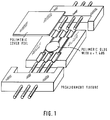
- a waveguide component which has fiber couplings. It consists of a base part made of polymeric material and a cover component, which is constructed as a negative form of the base part. V-shaped fiber coupling areas are provided at the outer ends. In the central region of the base part, a waveguide recess is provided, which is coated with an optical active ingredient, e.g. B. is provided with a UV-curing adhesive.
- an optical active ingredient e.g. B. is provided with a UV-curing adhesive.
- Figure 1 shows a similar waveguide component.
- the fibers to be coupled are aligned beforehand (prealignment fixture).
- PMMA cover foils polymeric cover foils
- a core monomer adhesive is dripped into the waveguide depressions, pressed out with a film to a thickness of less than 1 ⁇ m and then cured by UV or thermal polymerization.
- the core polymer has an approximately 5 * 10 -3 higher refractive index and thus represents a dielectric waveguide with the surrounding polymer substrate.
- the length of these foils must be cut to an accuracy of approx. +/- 10 ⁇ m.
- the fibers to be coupled are placed in the V-grooves before the waveguide is bonded and glued to the substrate by the overflowing core monomer.
- the method with the measures according to claim 1 makes it possible that the processes of the fastener adjustment and the waveguide gluing do not have to be carried out at the same time as in the solutions according to the prior art.
- the core material on the substrate surface can be expressed to a thickness of less than 1 ⁇ m without the passive fiber adjustment being destroyed or disturbed.
- Foil covers to be cut to size, as in the example shown in FIG. 1, are unnecessary since the foil cover can be replaced by a molded microstructured cover component.
- the method according to the invention is suitable for both to be glued, d. H. covers remaining on the substrate component, as well as for strip-off covers.
- the lid components do not have to be cut manually with high precision, but instead automatically fit to the associated substrate component with a high precision to a few ⁇ m, since they come from the same mask.
- the essential, applied design idea is the possibility to be able to produce positive and negative forms using a triple-copy technique in nickel electroplating.
- Polymer substrates for waveguide components are manufactured, for example, with 6 * 6 ⁇ m waveguide grooves and effectively 67 ⁇ m deep fiber guide grooves, which have to be glued with a higher refractive index, polymeric core material for further processing.
- the core material on the substrate surface must be expressed to a thickness of less than 1 ⁇ m, but the passive fiber adjustment must not be disturbed or destroyed.
- the present invention describes a method for producing an integrated optical waveguide component with a particularly favorable waveguide bond.
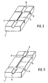
- FIG. 2 shows a silicon master structure and FIG. 3 shows a substrate component 1, which can represent both a passive (only waveguide grooves) and an active one (with embedded electro-optical components or heating electrodes).
- the waveguide structure area 3 can be seen, which is essentially transverse to the between two Fiber coupling areas - V-grooves 6 - arranged parallel grooves 4, 4 'extends.
- the master structure FIG. 2
- all structures, with the exception of the saw cuts, which represent the grooves 4, 4 ' are produced using an exposure mask and are therefore very precisely reproducible. Since the saw cut extends over the entire silicon wafer and there is practically no deviation from parallelism in the cutting direction, it can be assumed that the distance from the saw cut to the saw cut is always the same over the wafer.
- FIGS. 4 and 5 serve to explain the nickel electroplating copying technique.
- FIG. 4 shows 1st or 3rd generation nickel sheet obtained by electroplating, which can be used as cover component 2 without the webs in the waveguide structure area.
- the webs 5, 5 ' correspond to the grooves 4, 4' of the substrate component 1 and engage them in a precise fit when they are joined together.
- FIG. 5 shows a second generation nickel sheet from which a strip-off cover made of plastic can be molded.
- the invention is based on the knowledge that 1st, 2nd and 3rd generation nickel sheet are exact, better than ⁇ m accurate replicas, which differ only by a positive-negative conversion between two neighboring generations.
- FIG. 8 shows how, due to the geometric relationships described, a 3rd generation nickel sheet originating from the area AA 'snaps precisely into the saw cuts of the polymer substrate.
- the fiber guide grooves cannot be filled with core material, since the V-groove areas 6 of cover component 2 and substrate component are positive - negative identical copies that lie exactly on top of each other (webs 5, 5 '), especially with high mechanical pressure and a thin chrome plating Nickel strip-off cover in the V-groove area 6.
- the processes of waveguide formation in the structural area and the coupling of the fibers can thus be carried out at different times.
- a material of high optical transparency is used for the waveguide formation, whereas a material of high strength, in particular with regard to high temperature shock resistance, can be used for the coupling of the fibers.
- a disadvantage of the construction method described above i. is the permanent use of an expensive microstructured nickel sheet as a strip-off lid.
- incisions, holes, metallizations can be made on the microstructure cover etc. are not easily tested because the strip-off lid made of nickel is too valuable for risky modifications.
- the strip-off lid by plastic molding, z. B. by a thermoplastic impression, generated by a 2nd generation nickel, ie the molded plastic part is geometrically identical to a 3rd generation nickel strip-off cover, apart from changes in geometry due to different thermal expansion between metal and plastic, and can therefore be just like this be used if the plastic material has been correctly selected.
- Advantage of the construction process ii. is the possibility to produce almost any amount of strip-off lids by injection molding. In production, this gives you the option of using a separate cover component for each substrate component, so you do not need to clean the strip-off cover after each use. Chromium plating of the V-groove area with the aim of displacing the monomer from this area is like in method i. advantageous.
- the construction methods i. and ii. each produce a so-called strip-off waveguide, i.e. H. the waveguide core is initially unprotected on the surface of the polymer substrate and must therefore be protected with a polymer film in the next step.
- the third construction method iii. also uses a microstructure lid. However, this consists of a plastic that is glued by the core monomer, so that the cover can no longer be removed after the waveguide has been produced.
- the microstructure cover component 2 is molded from a mold insert that can be produced as follows: the starting point is a 2nd generation nickel sheet, which can be modified by fine mechanical rework. The V-groove area including the saw cut 4, 4 'is cut out from the associated 3rd generation nickel sheet. This part is reworked in such a way that its width just corresponds to the width of the fiber ribbon used later, i.e. z. B. for an eight-fiber ribbon 2 mm.
- the part is fitted into the V-groove area of the 2nd generation nickel sheet. Since both parts are inverse copies of each other, there is no gap in the saw cut of the 2nd generation nickel sheet (see Fig. 10). Then both parts are fixed by e.g. B. spot welding. Then the mold insert z. B. reworked by surface grinding so that ideally a 59.5 ⁇ m high step (Fig. 10). The molded from the mold insert, z. B. made of PMMA, press the fibers into the V-groove area of the substrate and at the same time close off the wave structure area 3 precisely, without a subsequent precise sawing as with conventional methods would be necessary.
- the negative-positive impression can also be taken in reverse order; d. H. as a starting form, a lid component is used, from which the substrate component is molded.
Applications Claiming Priority (2)
| Application Number | Priority Date | Filing Date | Title |
|---|---|---|---|
| DE19619353 | 1996-05-14 | ||
| DE19619353A DE19619353A1 (de) | 1996-05-14 | 1996-05-14 | Verfahren zur Herstellung eines integriert optischen Wellenleiterbauteiles sowie Anordnung |
Publications (2)
| Publication Number | Publication Date |
|---|---|
| EP0807836A2 true EP0807836A2 (fr) | 1997-11-19 |
| EP0807836A3 EP0807836A3 (fr) | 1997-12-17 |
Family
ID=7794244
Family Applications (1)
| Application Number | Title | Priority Date | Filing Date |
|---|---|---|---|
| EP97103691A Withdrawn EP0807836A3 (fr) | 1996-05-14 | 1997-03-06 | Procédé de fabrication d'un composant guide d'ondes integré et arrangement |
Country Status (3)
| Country | Link |
|---|---|
| US (1) | US5867619A (fr) |
| EP (1) | EP0807836A3 (fr) |
| DE (1) | DE19619353A1 (fr) |
Cited By (27)
| Publication number | Priority date | Publication date | Assignee | Title |
|---|---|---|---|---|
| EP1645633A2 (fr) | 2004-10-05 | 2006-04-12 | SunGene GmbH | Cassettes d'expression constitutives pour la régulation de l'expression chez les plantes. |
| EP1655364A2 (fr) | 2004-11-05 | 2006-05-10 | BASF Plant Science GmbH | Cassettes d'expression pour une expression préférentielle dans les graines |
| EP1662000A2 (fr) | 2004-11-25 | 2006-05-31 | SunGene GmbH | Cassettes d'expression pour l'expression préférée dans des cellules stomatiques de plantes |
| EP1666599A2 (fr) | 2004-12-04 | 2006-06-07 | SunGene GmbH | Cassettes d'expression pour l'expression préférée dans les cellules du mésophylle et/ou de l'épiderme de plantes |
| EP1669456A2 (fr) | 2004-12-11 | 2006-06-14 | SunGene GmbH | Cassettes d'expression pour l'expression preférentielle dans les méristèmes de plantes |
| EP1669455A2 (fr) | 2004-12-08 | 2006-06-14 | SunGene GmbH | Cassettes d'expression pour l'expression spécifique aux tissus vasculaires des plantes |
| WO2006089950A2 (fr) | 2005-02-26 | 2006-08-31 | Basf Plant Science Gmbh | Cassettes d'expression destinees a une expression preferentielle de semences chez des plantes |
| WO2006111512A1 (fr) | 2005-04-19 | 2006-10-26 | Basf Plant Science Gmbh | Methodes ameliorees controlant une expression genique |
| WO2006120197A2 (fr) | 2005-05-10 | 2006-11-16 | Basf Plant Science Gmbh | Cassettes d'expression pour l'expression preferentielle de semence dans des plantes |
| WO2006133983A1 (fr) | 2005-04-19 | 2006-12-21 | Basf Plant Science Gmbh | Expression specifique de l'albumen farineux et/ou de l'embryon en germination dans des plantes monocotyledonees |
| WO2008099013A1 (fr) | 2007-02-16 | 2008-08-21 | Basf Plant Science Gmbh | Séquences d'acides nucléiques pour la régulation de l'expression spécifique de l'embryon dans des plantes monocotyles |
| EP2036984A2 (fr) | 2002-07-26 | 2009-03-18 | BASF Plant Science GmbH | Reversion de l'effet sélectif négatif d'un protéin de marquage comme procédure de sélection |
| EP2045327A2 (fr) | 2005-03-08 | 2009-04-08 | BASF Plant Science GmbH | Expression à amélioration de séquences d'intron |
| EP2159289A2 (fr) | 2005-06-23 | 2010-03-03 | BASF Plant Science GmbH | Procédés améliorés pour la production de plants stablement transformés |
| EP2163635A1 (fr) | 2004-08-02 | 2010-03-17 | BASF Plant Science GmbH | Procédé d'isolation de séquence de terminaison de transcription |
| EP2186903A2 (fr) | 2005-02-09 | 2010-05-19 | BASF Plant Science GmbH | Cassettes d'expression pour la régulation de l'expression chez les plantes monocotylédones |
| WO2011003901A1 (fr) | 2009-07-10 | 2011-01-13 | Basf Plant Science Company Gmbh | Cassettes d'expression pour l'expression spécifiquement dans l'endosperme dans des plantes |
| EP2275564A1 (fr) | 2009-07-17 | 2011-01-19 | Freie Universität Berlin | Supports et procédé pour la production de plantes transgéniques qui résistent aux tumeurs |
| WO2011064750A1 (fr) | 2009-11-27 | 2011-06-03 | Basf Plant Science Company Gmbh | Endonucléases chimériques et utilisations de celles-ci |
| WO2011064736A1 (fr) | 2009-11-27 | 2011-06-03 | Basf Plant Science Company Gmbh | Endonucléases optimisées et leurs utilisations |
| WO2011067712A1 (fr) | 2009-12-03 | 2011-06-09 | Basf Plant Science Company Gmbh | Cassette d'expression pour expression spécifique de l'embryon dans des plantes |
| US8022272B2 (en) | 2001-07-13 | 2011-09-20 | Sungene Gmbh & Co. Kgaa | Expression cassettes for transgenic expression of nucleic acids |
| DE112010004584T5 (de) | 2009-11-27 | 2012-11-29 | Basf Plant Science Company Gmbh | Chimäre Endonukleasen und Anwendungen davon |
| EP2612918A1 (fr) | 2012-01-06 | 2013-07-10 | BASF Plant Science Company GmbH | Recombinaison in planta |
| EP2980220A1 (fr) | 2005-09-20 | 2016-02-03 | BASF Plant Science GmbH | Procédés améliorés de contrôle de l'expression de gènes |
| WO2021122080A1 (fr) | 2019-12-16 | 2021-06-24 | BASF Agricultural Solutions Seed US LLC | Édition génomique améliorée à l'aide de nickases appariées |
| WO2021122081A1 (fr) | 2019-12-16 | 2021-06-24 | Basf Se | Introduction précise d'adn ou de mutations dans le génome du blé |
Families Citing this family (10)
| Publication number | Priority date | Publication date | Assignee | Title |
|---|---|---|---|---|
| DE19842694A1 (de) * | 1998-09-17 | 2000-04-20 | Harting Elektrooptische Bauteile Gmbh & Co Kg | Mikrostrukturierter Körper sowie Verfahren zu seiner Herstellung |
| US6304695B1 (en) | 1999-05-17 | 2001-10-16 | Chiaro Networks Ltd. | Modulated light source |
| US6366720B1 (en) | 1999-07-09 | 2002-04-02 | Chiaro Networks Ltd. | Integrated optics beam deflector assemblies utilizing side mounting blocks for precise alignment |
| GB9919847D0 (en) * | 1999-08-20 | 1999-10-27 | British Telecomm | Alignment device |
| US7068870B2 (en) * | 2000-10-26 | 2006-06-27 | Shipley Company, L.L.C. | Variable width waveguide for mode-matching and method for making |
| US6813023B2 (en) | 2002-01-03 | 2004-11-02 | Chiaro Nerwork Ltd. | Automatic optical inter-alignment of two linear arrangements |
| US6886994B2 (en) * | 2002-07-18 | 2005-05-03 | Chiaro Networks Ltd. | Optical assembly and method for manufacture thereof |
| US6808322B2 (en) * | 2002-09-24 | 2004-10-26 | Triquint Technology Holding Co. | Devices and method of mounting |
| KR100476317B1 (ko) * | 2002-10-24 | 2005-03-16 | 한국전자통신연구원 | 광결합 소자 및 그 제작 방법, 광결합 소자 제작을 위한마스터 및 그 제작 방법 |
| CN107144919A (zh) * | 2017-06-28 | 2017-09-08 | 湖北工业大学 | 一种聚合物光波导芯片的制作方法 |
Citations (4)
| Publication number | Priority date | Publication date | Assignee | Title |
|---|---|---|---|---|
| WO1993021550A1 (fr) * | 1992-04-10 | 1993-10-28 | Robert Bosch Gmbh | Procede pour la fabrication de composants optiques en polymere avec couplage integre puce/fibre par moulage |
| EP0589268A1 (fr) * | 1992-09-17 | 1994-03-30 | Robert Bosch Gmbh | Circuit optique integré avec une structure de Bragg |
| EP0608566A2 (fr) * | 1992-12-28 | 1994-08-03 | Matsushita Electric Industrial Co., Ltd. | Substrat pour monter des composants optiques et son procédé de production |
| US5343544A (en) * | 1993-07-02 | 1994-08-30 | Minnesota Mining And Manufacturing Company | Integrated optical fiber coupler and method of making same |
Family Cites Families (4)
| Publication number | Priority date | Publication date | Assignee | Title |
|---|---|---|---|---|
| US4639074A (en) * | 1984-06-18 | 1987-01-27 | At&T Bell Laboratories | Fiber-waveguide self alignment coupler |
| FR2661516B1 (fr) * | 1990-04-27 | 1992-06-12 | Alcatel Fibres Optiques | Composant d'optique integree et procede de fabrication. |
| FR2692684B1 (fr) * | 1992-06-19 | 1997-04-04 | Corning Inc | Composant optique connecte a un reseau de fibres optiques. |
| US5600745A (en) * | 1996-02-08 | 1997-02-04 | Industrial Technology Research Institute | Method of automatically coupling between a fiber and an optical waveguide |
-
1996
- 1996-05-14 DE DE19619353A patent/DE19619353A1/de not_active Withdrawn
-
1997
- 1997-03-06 EP EP97103691A patent/EP0807836A3/fr not_active Withdrawn
- 1997-05-12 US US08/854,860 patent/US5867619A/en not_active Expired - Fee Related
Patent Citations (4)
| Publication number | Priority date | Publication date | Assignee | Title |
|---|---|---|---|---|
| WO1993021550A1 (fr) * | 1992-04-10 | 1993-10-28 | Robert Bosch Gmbh | Procede pour la fabrication de composants optiques en polymere avec couplage integre puce/fibre par moulage |
| EP0589268A1 (fr) * | 1992-09-17 | 1994-03-30 | Robert Bosch Gmbh | Circuit optique integré avec une structure de Bragg |
| EP0608566A2 (fr) * | 1992-12-28 | 1994-08-03 | Matsushita Electric Industrial Co., Ltd. | Substrat pour monter des composants optiques et son procédé de production |
| US5343544A (en) * | 1993-07-02 | 1994-08-30 | Minnesota Mining And Manufacturing Company | Integrated optical fiber coupler and method of making same |
Cited By (43)
| Publication number | Priority date | Publication date | Assignee | Title |
|---|---|---|---|---|
| US8022272B2 (en) | 2001-07-13 | 2011-09-20 | Sungene Gmbh & Co. Kgaa | Expression cassettes for transgenic expression of nucleic acids |
| US8604278B2 (en) | 2001-07-13 | 2013-12-10 | Sungene Gmbh & Co. Kgaa | Expression cassettes for transgenic expression of nucleic acids |
| EP2036984A2 (fr) | 2002-07-26 | 2009-03-18 | BASF Plant Science GmbH | Reversion de l'effet sélectif négatif d'un protéin de marquage comme procédure de sélection |
| EP2166104A1 (fr) | 2004-08-02 | 2010-03-24 | BASF Plant Science GmbH | Procédé d'isolation de séquence de terminaison de transcription |
| EP2163635A1 (fr) | 2004-08-02 | 2010-03-17 | BASF Plant Science GmbH | Procédé d'isolation de séquence de terminaison de transcription |
| EP2166103A1 (fr) | 2004-08-02 | 2010-03-24 | BASF Plant Science GmbH | Procédé d'isolation de séquence de terminaison de transcription |
| EP2166097A1 (fr) | 2004-10-05 | 2010-03-24 | SunGene GmbH | Cassettes d'expression constitutive pour la régulation de l'expression chez les plantes |
| EP1645633A2 (fr) | 2004-10-05 | 2006-04-12 | SunGene GmbH | Cassettes d'expression constitutives pour la régulation de l'expression chez les plantes. |
| EP2166098A1 (fr) | 2004-10-05 | 2010-03-24 | SunGene GmbH | Cassettes d'expression constitutive pour la régulation de l'expression chez les plantes |
| EP1655364A2 (fr) | 2004-11-05 | 2006-05-10 | BASF Plant Science GmbH | Cassettes d'expression pour une expression préférentielle dans les graines |
| EP1662000A2 (fr) | 2004-11-25 | 2006-05-31 | SunGene GmbH | Cassettes d'expression pour l'expression préférée dans des cellules stomatiques de plantes |
| EP2163631A1 (fr) | 2004-11-25 | 2010-03-17 | SunGene GmbH | Cassettes d'expression pour l'expression préférée dans des cellules stomatiques de plantes |
| EP1666599A2 (fr) | 2004-12-04 | 2006-06-07 | SunGene GmbH | Cassettes d'expression pour l'expression préférée dans les cellules du mésophylle et/ou de l'épiderme de plantes |
| EP1669455A2 (fr) | 2004-12-08 | 2006-06-14 | SunGene GmbH | Cassettes d'expression pour l'expression spécifique aux tissus vasculaires des plantes |
| EP2072620A2 (fr) | 2004-12-08 | 2009-06-24 | SunGene GmbH | Cassettes d'expression pour l'expression spécifique aux tissus vasculaires des plantes |
| EP1669456A2 (fr) | 2004-12-11 | 2006-06-14 | SunGene GmbH | Cassettes d'expression pour l'expression preférentielle dans les méristèmes de plantes |
| EP2186903A2 (fr) | 2005-02-09 | 2010-05-19 | BASF Plant Science GmbH | Cassettes d'expression pour la régulation de l'expression chez les plantes monocotylédones |
| WO2006089950A2 (fr) | 2005-02-26 | 2006-08-31 | Basf Plant Science Gmbh | Cassettes d'expression destinees a une expression preferentielle de semences chez des plantes |
| EP2045327A2 (fr) | 2005-03-08 | 2009-04-08 | BASF Plant Science GmbH | Expression à amélioration de séquences d'intron |
| EP2166101A2 (fr) | 2005-03-08 | 2010-03-24 | BASF Plant Science GmbH | Séquences introniques facilitant l'expression |
| EP2166099A2 (fr) | 2005-03-08 | 2010-03-24 | BASF Plant Science GmbH | Expression à amélioration de séquences d'intron |
| EP2166100A2 (fr) | 2005-03-08 | 2010-03-24 | BASF Plant Science GmbH | Séquences introniques facilitant l'expression |
| EP2169058A2 (fr) | 2005-03-08 | 2010-03-31 | BASF Plant Science GmbH | Expression à amélioration de séquences d'intron |
| EP2166102A2 (fr) | 2005-03-08 | 2010-03-24 | BASF Plant Science GmbH | Expression à amélioration de séquences d'intron |
| WO2006111512A1 (fr) | 2005-04-19 | 2006-10-26 | Basf Plant Science Gmbh | Methodes ameliorees controlant une expression genique |
| WO2006133983A1 (fr) | 2005-04-19 | 2006-12-21 | Basf Plant Science Gmbh | Expression specifique de l'albumen farineux et/ou de l'embryon en germination dans des plantes monocotyledonees |
| WO2006120197A2 (fr) | 2005-05-10 | 2006-11-16 | Basf Plant Science Gmbh | Cassettes d'expression pour l'expression preferentielle de semence dans des plantes |
| EP2159289A2 (fr) | 2005-06-23 | 2010-03-03 | BASF Plant Science GmbH | Procédés améliorés pour la production de plants stablement transformés |
| EP2980220A1 (fr) | 2005-09-20 | 2016-02-03 | BASF Plant Science GmbH | Procédés améliorés de contrôle de l'expression de gènes |
| WO2008099013A1 (fr) | 2007-02-16 | 2008-08-21 | Basf Plant Science Gmbh | Séquences d'acides nucléiques pour la régulation de l'expression spécifique de l'embryon dans des plantes monocotyles |
| WO2011003901A1 (fr) | 2009-07-10 | 2011-01-13 | Basf Plant Science Company Gmbh | Cassettes d'expression pour l'expression spécifiquement dans l'endosperme dans des plantes |
| EP2275564A1 (fr) | 2009-07-17 | 2011-01-19 | Freie Universität Berlin | Supports et procédé pour la production de plantes transgéniques qui résistent aux tumeurs |
| DE112010004583T5 (de) | 2009-11-27 | 2012-10-18 | Basf Plant Science Company Gmbh | Chimäre Endonukleasen und Anwendungen davon |
| WO2011064736A1 (fr) | 2009-11-27 | 2011-06-03 | Basf Plant Science Company Gmbh | Endonucléases optimisées et leurs utilisations |
| DE112010004584T5 (de) | 2009-11-27 | 2012-11-29 | Basf Plant Science Company Gmbh | Chimäre Endonukleasen und Anwendungen davon |
| DE112010004582T5 (de) | 2009-11-27 | 2012-11-29 | Basf Plant Science Company Gmbh | Optimierte Endonukleasen und Anwendungen davon |
| WO2011064750A1 (fr) | 2009-11-27 | 2011-06-03 | Basf Plant Science Company Gmbh | Endonucléases chimériques et utilisations de celles-ci |
| WO2011067712A1 (fr) | 2009-12-03 | 2011-06-09 | Basf Plant Science Company Gmbh | Cassette d'expression pour expression spécifique de l'embryon dans des plantes |
| EP3002332A2 (fr) | 2009-12-03 | 2016-04-06 | BASF Plant Science Company GmbH | Cassettes d'expression pour expression spécifique à des embryons dans des plantes |
| EP2612918A1 (fr) | 2012-01-06 | 2013-07-10 | BASF Plant Science Company GmbH | Recombinaison in planta |
| WO2013102875A1 (fr) | 2012-01-06 | 2013-07-11 | Basf Plant Science Company Gmbh | Recombinaison in planta |
| WO2021122080A1 (fr) | 2019-12-16 | 2021-06-24 | BASF Agricultural Solutions Seed US LLC | Édition génomique améliorée à l'aide de nickases appariées |
| WO2021122081A1 (fr) | 2019-12-16 | 2021-06-24 | Basf Se | Introduction précise d'adn ou de mutations dans le génome du blé |
Also Published As
| Publication number | Publication date |
|---|---|
| DE19619353A1 (de) | 1997-11-20 |
| US5867619A (en) | 1999-02-02 |
| EP0807836A3 (fr) | 1997-12-17 |
Similar Documents
| Publication | Publication Date | Title |
|---|---|---|
| EP0807836A2 (fr) | Procédé de fabrication d'un composant guide d'ondes integré et arrangement | |
| EP0560043B1 (fr) | Méthode de fabrication d'éléments pour des réseaux de guide d'ondes et éléments fabriqués utilisant cette méthode | |
| EP0635139B1 (fr) | Procede pour la fabrication de composants optiques en polymere avec couplage integre puce/fibre par moulage | |
| EP0622647A2 (fr) | Guide d'onde optique à substrat plan et son utilisation | |
| EP0429877B1 (fr) | Dispositif de positionnement de fibres optiques dans des éléments de connexion | |
| EP0883825B1 (fr) | Procede de production de composants optiques avec guides d'ondes optiques accouples, et composants optiques produits selon ce procede | |
| DE60309669T2 (de) | Verfahren zur herstellung einer optischen vorrichtung mittels eines replikationsverfahrens | |
| EP0445527A2 (fr) | Composante optique de guide d'onde et m˩thode de fabrication d'une composante optique de guide d'onde | |
| DE4401219A1 (de) | Integriert optisches Bauelement und Verfahren zur Herstellung eines integriert optischen Bauelements | |
| DE4440981A1 (de) | Optisches Verbundbauelement vom Reflexionstyp | |
| EP0037007B1 (fr) | Procédé de fabrication d'un coupleur optique à 4 portes | |
| DE4200397C1 (fr) | ||
| DE4423842C2 (de) | Steckverbinder für Lichtwellenleiter und Formeinsatz zur Herstellung desselben | |
| EP0576999A1 (fr) | Méthode et dispositif pour produire des éléments optiques | |
| EP0589268B1 (fr) | Circuit optique integré avec une structure de Bragg | |
| WO1994028449A1 (fr) | Procede de fabrication d'elements de guidage pour guides d'ondes lumineuses a fibres optiques | |
| EP1005663B1 (fr) | Procede de production d'un composant optique integre a la puce a guides d'ondes avec connecteur enfichable | |
| EP1671167B1 (fr) | Procede de realisation de cartes de circuits imprimes electro-optiques comprenant des guides d'onde polysiloxane, et leur utilisation | |
| DE19602736A1 (de) | Verfahren und Vorrichtung zur Herstellung von optischen Linsen und optischen Linsenarrays | |
| DE3712145A1 (de) | Optisches bauelement mit veraenderlicher brennweite | |
| DE4200396C1 (fr) | ||
| DE2926003A1 (de) | Vorrichtung und verfahren zur herstellung von teilen eines optischen verzweigerelementes | |
| DE3810044A1 (de) | Verfahren zum herstellen eines traegerteils mit hochpraezisen nuten | |
| DE3112887C2 (de) | Verfahren zur Herstellung eines Koppelelementes zum Ein- und/oder Auskoppeln von Licht | |
| EP0523514A1 (fr) | Procédé pour fabriquer un coupleur optique planaire |
Legal Events
| Date | Code | Title | Description |
|---|---|---|---|
| PUAI | Public reference made under article 153(3) epc to a published international application that has entered the european phase |
Free format text: ORIGINAL CODE: 0009012 |
|
| PUAL | Search report despatched |
Free format text: ORIGINAL CODE: 0009013 |
|
| AK | Designated contracting states |
Kind code of ref document: A2 Designated state(s): DE FR GB IT |
|
| AK | Designated contracting states |
Kind code of ref document: A3 Designated state(s): DE FR GB IT |
|
| 17P | Request for examination filed |
Effective date: 19980617 |
|
| RAP1 | Party data changed (applicant data changed or rights of an application transferred) |
Owner name: HARTING ELEKTRO-OPTISCHE BAUTEILE GMBH & CO. KG. |
|
| STAA | Information on the status of an ep patent application or granted ep patent |
Free format text: STATUS: THE APPLICATION IS DEEMED TO BE WITHDRAWN |
|
| 18D | Application deemed to be withdrawn |
Effective date: 20021001 |