EP0807772A2 - Method for driving a vehicle with plural prime movers - Google Patents
Method for driving a vehicle with plural prime movers Download PDFInfo
- Publication number
- EP0807772A2 EP0807772A2 EP97107057A EP97107057A EP0807772A2 EP 0807772 A2 EP0807772 A2 EP 0807772A2 EP 97107057 A EP97107057 A EP 97107057A EP 97107057 A EP97107057 A EP 97107057A EP 0807772 A2 EP0807772 A2 EP 0807772A2
- Authority
- EP
- European Patent Office
- Prior art keywords
- drive
- transmission
- control device
- machine
- downstream
- Prior art date
- Legal status (The legal status is an assumption and is not a legal conclusion. Google has not performed a legal analysis and makes no representation as to the accuracy of the status listed.)
- Granted
Links
Images

Classifications
-
- B—PERFORMING OPERATIONS; TRANSPORTING
- B60—VEHICLES IN GENERAL
- B60W—CONJOINT CONTROL OF VEHICLE SUB-UNITS OF DIFFERENT TYPE OR DIFFERENT FUNCTION; CONTROL SYSTEMS SPECIALLY ADAPTED FOR HYBRID VEHICLES; ROAD VEHICLE DRIVE CONTROL SYSTEMS FOR PURPOSES NOT RELATED TO THE CONTROL OF A PARTICULAR SUB-UNIT
- B60W10/00—Conjoint control of vehicle sub-units of different type or different function
- B60W10/10—Conjoint control of vehicle sub-units of different type or different function including control of change-speed gearings
-
- B—PERFORMING OPERATIONS; TRANSPORTING
- B60—VEHICLES IN GENERAL
- B60K—ARRANGEMENT OR MOUNTING OF PROPULSION UNITS OR OF TRANSMISSIONS IN VEHICLES; ARRANGEMENT OR MOUNTING OF PLURAL DIVERSE PRIME-MOVERS IN VEHICLES; AUXILIARY DRIVES FOR VEHICLES; INSTRUMENTATION OR DASHBOARDS FOR VEHICLES; ARRANGEMENTS IN CONNECTION WITH COOLING, AIR INTAKE, GAS EXHAUST OR FUEL SUPPLY OF PROPULSION UNITS IN VEHICLES
- B60K17/00—Arrangement or mounting of transmissions in vehicles
- B60K17/04—Arrangement or mounting of transmissions in vehicles characterised by arrangement, location or kind of gearing
- B60K17/06—Arrangement or mounting of transmissions in vehicles characterised by arrangement, location or kind of gearing of change-speed gearing
- B60K17/08—Arrangement or mounting of transmissions in vehicles characterised by arrangement, location or kind of gearing of change-speed gearing of mechanical type
-
- B—PERFORMING OPERATIONS; TRANSPORTING
- B60—VEHICLES IN GENERAL
- B60K—ARRANGEMENT OR MOUNTING OF PROPULSION UNITS OR OF TRANSMISSIONS IN VEHICLES; ARRANGEMENT OR MOUNTING OF PLURAL DIVERSE PRIME-MOVERS IN VEHICLES; AUXILIARY DRIVES FOR VEHICLES; INSTRUMENTATION OR DASHBOARDS FOR VEHICLES; ARRANGEMENTS IN CONNECTION WITH COOLING, AIR INTAKE, GAS EXHAUST OR FUEL SUPPLY OF PROPULSION UNITS IN VEHICLES
- B60K17/00—Arrangement or mounting of transmissions in vehicles
- B60K17/34—Arrangement or mounting of transmissions in vehicles for driving both front and rear wheels, e.g. four wheel drive vehicles
- B60K17/356—Arrangement or mounting of transmissions in vehicles for driving both front and rear wheels, e.g. four wheel drive vehicles having fluid or electric motor, for driving one or more wheels
-
- B—PERFORMING OPERATIONS; TRANSPORTING
- B60—VEHICLES IN GENERAL
- B60K—ARRANGEMENT OR MOUNTING OF PROPULSION UNITS OR OF TRANSMISSIONS IN VEHICLES; ARRANGEMENT OR MOUNTING OF PLURAL DIVERSE PRIME-MOVERS IN VEHICLES; AUXILIARY DRIVES FOR VEHICLES; INSTRUMENTATION OR DASHBOARDS FOR VEHICLES; ARRANGEMENTS IN CONNECTION WITH COOLING, AIR INTAKE, GAS EXHAUST OR FUEL SUPPLY OF PROPULSION UNITS IN VEHICLES
- B60K6/00—Arrangement or mounting of plural diverse prime-movers for mutual or common propulsion, e.g. hybrid propulsion systems comprising electric motors and internal combustion engines
- B60K6/20—Arrangement or mounting of plural diverse prime-movers for mutual or common propulsion, e.g. hybrid propulsion systems comprising electric motors and internal combustion engines the prime-movers consisting of electric motors and internal combustion engines, e.g. HEVs
- B60K6/50—Architecture of the driveline characterised by arrangement or kind of transmission units
- B60K6/52—Driving a plurality of drive axles, e.g. four-wheel drive
-
- F—MECHANICAL ENGINEERING; LIGHTING; HEATING; WEAPONS; BLASTING
- F16—ENGINEERING ELEMENTS AND UNITS; GENERAL MEASURES FOR PRODUCING AND MAINTAINING EFFECTIVE FUNCTIONING OF MACHINES OR INSTALLATIONS; THERMAL INSULATION IN GENERAL
- F16H—GEARING
- F16H61/00—Control functions within control units of change-speed- or reversing-gearings for conveying rotary motion ; Control of exclusively fluid gearing, friction gearing, gearings with endless flexible members or other particular types of gearing
- F16H61/02—Control functions within control units of change-speed- or reversing-gearings for conveying rotary motion ; Control of exclusively fluid gearing, friction gearing, gearings with endless flexible members or other particular types of gearing characterised by the signals used
- F16H61/0202—Control functions within control units of change-speed- or reversing-gearings for conveying rotary motion ; Control of exclusively fluid gearing, friction gearing, gearings with endless flexible members or other particular types of gearing characterised by the signals used the signals being electric
- F16H61/0204—Control functions within control units of change-speed- or reversing-gearings for conveying rotary motion ; Control of exclusively fluid gearing, friction gearing, gearings with endless flexible members or other particular types of gearing characterised by the signals used the signals being electric for gearshift control, e.g. control functions for performing shifting or generation of shift signal
- F16H61/0213—Control functions within control units of change-speed- or reversing-gearings for conveying rotary motion ; Control of exclusively fluid gearing, friction gearing, gearings with endless flexible members or other particular types of gearing characterised by the signals used the signals being electric for gearshift control, e.g. control functions for performing shifting or generation of shift signal characterised by the method for generating shift signals
-
- B—PERFORMING OPERATIONS; TRANSPORTING
- B60—VEHICLES IN GENERAL
- B60K—ARRANGEMENT OR MOUNTING OF PROPULSION UNITS OR OF TRANSMISSIONS IN VEHICLES; ARRANGEMENT OR MOUNTING OF PLURAL DIVERSE PRIME-MOVERS IN VEHICLES; AUXILIARY DRIVES FOR VEHICLES; INSTRUMENTATION OR DASHBOARDS FOR VEHICLES; ARRANGEMENTS IN CONNECTION WITH COOLING, AIR INTAKE, GAS EXHAUST OR FUEL SUPPLY OF PROPULSION UNITS IN VEHICLES
- B60K1/00—Arrangement or mounting of electrical propulsion units
- B60K1/02—Arrangement or mounting of electrical propulsion units comprising more than one electric motor
-
- Y—GENERAL TAGGING OF NEW TECHNOLOGICAL DEVELOPMENTS; GENERAL TAGGING OF CROSS-SECTIONAL TECHNOLOGIES SPANNING OVER SEVERAL SECTIONS OF THE IPC; TECHNICAL SUBJECTS COVERED BY FORMER USPC CROSS-REFERENCE ART COLLECTIONS [XRACs] AND DIGESTS
- Y02—TECHNOLOGIES OR APPLICATIONS FOR MITIGATION OR ADAPTATION AGAINST CLIMATE CHANGE
- Y02T—CLIMATE CHANGE MITIGATION TECHNOLOGIES RELATED TO TRANSPORTATION
- Y02T10/00—Road transport of goods or passengers
- Y02T10/60—Other road transportation technologies with climate change mitigation effect
- Y02T10/62—Hybrid vehicles
Definitions
- the invention relates to a method and a device for operating a vehicle with a plurality of drive machines according to the preamble of claims 1 and 6.
- Electric machines are increasingly being used today to drive vehicles, especially commercial vehicles in road traffic (see, for example, "An electric single-wheel drive for city buses of the future" by B. Wüst, R. Müller, A. Lange in “DER NAHVERKEHR”, 6/1994, Albatschverlag, Düsseldorf).
- the object of the invention is therefore to overcome the disadvantages of the prior art and to provide a method for driving a vehicle with a plurality of drive machines and a control device therefor, which allows the drive system to always be operated in the range of the optimum efficiency even for different speed ranges and to constantly provide the required tractive force.
- a synchronized or unsynchronized multi-stage transmission which optimizes the ranges, is connected downstream of each of the prime movers, which are preferably electrical machines, in a vehicle comprising a plurality of prime movers, each of which drives a wheel or an axle Efficiency is transformed into other output speeds and these gears are controlled according to the method and the control device according to the invention such that only a brief reduction in the tractive force or no interruption in tractive force occurs.
- the invention proposes, according to the characterizing part of the method according to the invention, that when the switching point is reached, the downstream gears are shifted in time so that there is no interruption in tractive force.
- the control device for driving control for such a vehicle is designed so that the control device has a first memory area in which the speed is read in and the overall efficiency of the drive machine is determined on the basis of a characteristic field, the control device is connected to the transmission downstream of the first drive machine via a first switching line, such that when the switching point is reached a switching pulse for switching the transmission is supplied via the switching line, and the Control device is connected to the transmission downstream of the second drive machine via a second switching line, such that a switching pulse for switching the transmission is supplied to the transmission after the first transmission has been switched over.
- the drive machine is an electrical machine, preferably a transverse flux machine, as is known, for example, from German patent DE 39 27 453 D2.
- the drive machines can be assigned to each wheel of an axle, or only to the respective axles. According to the arrangement of the drive machines, it is possible in a first embodiment of the invention that first the transmission of the drive machine, which acts on the front axle, is switched, and then the transmission, which acts on the rear axle, or vice versa.
- gearboxes are conceivable: In a first embodiment it can be provided that first the gearbox of the left wheel drive is switched in the direction of travel of the front or rear axle and then that Gearbox of the drive machine of the right wheel of the front or rear axle.
- Particularly preferred is an embodiment in which the power of the prime mover, the transmission of which is not shifted, is increased in order to compensate for the interruption in tractive force caused by the shifting, which occurs on the other transmission, in such a way that there is no reduction in tractive force at all.
- gears As a gear it is provided that multi-stage, preferably two-stage gears are used. A particularly inexpensive design can be realized if the gears are designed as very simple claw gears, which can either be synchronized or unsynchronized. Automatically shifting or shiftable transmissions are particularly preferred for carrying out the method according to the invention.
- the drive machine in the present case the motor-operated transverse flux machine, is operating in the optimum range with regard to the efficiency.
- a new value is read in after a read-in waiting time ⁇ T, which can be in the range from 1 ms to 1 s. If the prime mover does not work in the optimal range, the downstream transmission should be switched over. In this way, it is possible to transform the range of the optimal efficiency of the electrical machine into another output speed range. For example, in the case of a two-stage gearbox, the range of optimal efficiency can then be passed through twice, which increases the overall efficiency becomes.
- the invention provides that the transmissions assigned to the different drive machines are not switched simultaneously but in succession. In the exemplary embodiment shown here, this is achieved by first switching the transmission of the first drive machine. In the embodiment shown, a query is made as to whether the switchover has taken place, this can be done, for example, by again determining the current speed value of the drive machine at periodic query time intervals ⁇ t. If the switchover has not yet taken place, the query is carried out again after ⁇ t. If, on the other hand, the transmission of the first drive machine has been switched over, the transmission of the second drive machine is subsequently switched over.
- the front axle can be assigned a drive machine with a transmission and the rear axle can be assigned the same. It is then possible to first switch the gearbox of the front axle drive machine and then the gearbox of the rear axle or vice versa.
- each wheel of an axle is assigned its own drive machine with a downstream transmission.
- the following switching sequence options then result: First, the gearbox assigned to the drive machine on the left in the direction of travel of the front axle is shifted and then that of the drive machine in the right wheel is seen in the direction of travel.
- the switching process on the rear axle then takes place analogously to that of the front axle.
- a cross connection is provided. This means that first the gear of a wheel of the front axle is switched, for example that assigned to the left wheel as seen in the direction of travel, and then the gear of the right wheel of the rear axle.
- a driving control device for performing this method is also specified.
- Such an exemplary device is shown in Figure 2.
- Figure 1 shows the drive machines 1, 2 assigned to the respective wheels 5, 6 of an axle, which can be the front axle or rear axle, and the downstream gearboxes 3, 4.
- the downstream transmissions are multi-stage, preferably two-stage transmissions, which can be synchronized or unsynchronized. It is particularly advantageous to provide a two-stage dog gear as a gear (see, for example, Dubbel, Taschenbuch für den Maschinenbau, 1996, pages G 63 to G 195), which are characterized in particular by a simple gear structure. Furthermore, such gearboxes only require auxiliary energy during the shifting, as a result of which the loss in efficiency through the gearbox itself is low.
- the respective drive unit comprising the drive machine, which in the present case is a transverse flux machine, and the transmission are each assigned to a wheel.
- the transverse flux machine 1 and the downstream transmission 3 are assigned to the left wheel 5 seen in the direction of travel, and in an analogous manner the transverse flux machine 2 and the transmission 4 are assigned to the right wheel 6 seen in the direction of travel.
- Both the transverse flux motors 1, 2 and the gears 3, 4 are connected via control lines 7, 8, 9, 10 to a control device 20, which is preferably a microcomputer with corresponding outputs.
- Measuring lines 21, 22, which are also connected to the control device, are provided between the transverse flux machine and the subsequent transmission. Measuring signals, which are picked up by means of sensors or sensors from the transverse flux machine, are sent to the Control device transmitted. In one embodiment, the sensors or sensors can be speed sensors with which the instantaneous speed of the transverse flux machine is determined. With the help of the control lines 7, 8, 9, 10, control signals are transmitted both to the transverse flux machine and to the downstream transmission.
- the control lines 9, 10 can be used, for example, to transmit signals to an actuator which actuates the transmission, that is to say in the present case, switches over. Commercially available solenoid valves, such as those used for transmission control, are conceivable as actuators.
- the control lines 7, 8 connected to the transverse flux machine make it possible to control them, for example to increase the power output briefly, as long as the transmission of the other machine is switched over, so that an interruption in traction is commented on.
- the present invention thus for the first time specifies a method and a device for operating a vehicle with a plurality of drive machines, in which it is possible to increase the overall efficiency by using simply constructed gears.
Landscapes
- Engineering & Computer Science (AREA)
- Mechanical Engineering (AREA)
- Chemical & Material Sciences (AREA)
- Combustion & Propulsion (AREA)
- Transportation (AREA)
- General Engineering & Computer Science (AREA)
- Control Of Transmission Device (AREA)
- Electric Propulsion And Braking For Vehicles (AREA)
Abstract
Description
Die Erfindung betrifft ein Verfahren und eine Vorrichtung zum Betreiben eines Fahrzeuges mit mehreren Antriebsmaschinen gemäß dem Oberbegriff der Ansprüche 1 und 6.The invention relates to a method and a device for operating a vehicle with a plurality of drive machines according to the preamble of claims 1 and 6.
Elektrische Maschinen finden heute vermehrt Verwendung auch zum Antrieb von Fahrzeugen, insbesondere Nutzfahrzeugen im Straßenverkehr (siehe z.B. "Ein elektrischer Einzelradantrieb für Citybusse der Zukunft" von B. Wüst, R. Müller, A. Lange in "DER NAHVERKEHR", 6/1994, Alba Fachverlag, Düsseldorf).Electric machines are increasingly being used today to drive vehicles, especially commercial vehicles in road traffic (see, for example, "An electric single-wheel drive for city buses of the future" by B. Wüst, R. Müller, A. Lange in "DER NAHVERKEHR", 6/1994, Alba Fachverlag, Düsseldorf).
Bei elektrischen Maschinen gibt es Betriebsbereiche mit sehr gutem Wirkungsgrad und Betriebsbereiche mit niedrigerem Wirkungsgrad. Werden elektrische Maschinen wie in oben genanntem Artikel beschrieben in Fahrzeugen eingesetzt, so wird in der Regel das Antriebssystem so ausgelegt, daß der überwiegende Betriebsanteil in den Bereichen optimalen Wirkungsgrades stattfindet. Der Betrieb in den Bereichen geringeren Wirkungsgrades läßt sich jedoch aufgrund der benötigten Drehzahlbereiche nicht vermeiden. Deshalb wird in verschiedenen Einsatzfällen der elektrischen Maschinen ein Getriebe nachgeschaltet. Dieses Getriebe hat aber den Nachteil, daß eine Zugkraftunterbrechung während der Schaltung, z.B. bei einem Klauengetriebe, auftritt bzw. zur Vermeidung einer solchen Zugkraftunterbrechung ein entsprechend aufwendiges Getriebe eingesetzt werden muß, wie z.B. ein Planetengetriebe mit Lamellenkupplung oder - bremse.Electrical machines have operating areas with very good efficiency and operating areas with lower efficiency. If electrical machines are used in vehicles as described in the article mentioned above, the drive system is usually designed so that the predominant part of the operation takes place in the areas of optimum efficiency. However, operation in the areas of lower efficiency cannot be avoided due to the required speed ranges. For this reason, a gearbox is installed in various electrical machine applications. However, this transmission has the disadvantage that an interruption in traction during the shift, e.g. occurs in a dog gear, or a correspondingly complex gear must be used to avoid such an interruption in tractive force, such as a planetary gear with multi-plate clutch or brake.
Wegen der mit dem Schaltvorgang einhergehenden Zugkraftunterbrechung sind bislang für die Antriebssysteme von Straßenfahrzeugen immer nur Radgetriebe mit konstanter Übersetzung vorgesehen gewesen (siehe z.B. o.g. Veröffentlichung "Ein elektrischer Einzelradantrieb für City-Busse der Zukunft").Because of the interruption in tractive power associated with the gearshift, up to now have only been for the drive systems of road vehicles Wheel transmissions with constant gear ratios were provided (see egog publication "An electric single wheel drive for city buses of the future").
Des weiteren ist ein Einsatz von selbsttätig schaltenden bzw. schaltbaren Getrieben im Stand der Technik für Elektroantriebe bislang ausgeschlossen worden, da hierfür zuviel Energie aufgewandt werden mußte.Furthermore, the use of automatically switching or switchable transmissions in the prior art for electric drives has been ruled out to date, since too much energy had to be used for this.
Aufgabe der Erfindung ist es somit, die Nachteile des Standes der Technik zu überwinden und ein Verfahren zum Antrieb eines Fahrzeuges mit mehreren Antriebsmaschinen und eine Steuereinrichtung hierfür anzugeben, die es erlaubt, das Antriebssystem auch für unterschiedliche Drehzahlbereiche immer im Bereich des optimalen Wirkungsgrades zu betreiben und ständig die benötigte Zugkraft zur Verfügung zu stellen.The object of the invention is therefore to overcome the disadvantages of the prior art and to provide a method for driving a vehicle with a plurality of drive machines and a control device therefor, which allows the drive system to always be operated in the range of the optimum efficiency even for different speed ranges and to constantly provide the required tractive force.
Zur Lösung dieser Aufgabe ist erfindungsgemäß vorgesehen, daß bei einem Fahrzeug, das mehrere Antriebsmaschinen umfaßt, die jeweils ein Rad oder eine Achse antreiben, jeder der Antriebsmaschinen, die vorzugsweise elektrische Maschinen sind, ein synchronisiertes oder unsynchronisiertes mehrstufiges Getriebe nachgeschaltet ist, das die Bereiche optimalen Wirkungsgrades in andere Abtriebsdrehzahlen transformiert und diese Getriebe gemäß dem erfindungsgemäßen Verfahren und der erfindungsgemäßen Steuervorrichtung derart gesteuert werden, daß nur eine kurzzeitige Reduzierung der Zugkraft bzw. keine Zugkraftunterbrechung auftritt. Hierzu schlägt die Erfindung gemäß dem kennzeichnenden Teil des erfindungsgemäßen Verfahrens nach Anspruch 1 vor, daß bei Erreichen des Schaltpunktes die nachgeordneten Getriebe zeitlich versetzt geschaltet werden, damit keine Zugkraftunterbrechung auftritt.To achieve this object, it is provided according to the invention that a synchronized or unsynchronized multi-stage transmission, which optimizes the ranges, is connected downstream of each of the prime movers, which are preferably electrical machines, in a vehicle comprising a plurality of prime movers, each of which drives a wheel or an axle Efficiency is transformed into other output speeds and these gears are controlled according to the method and the control device according to the invention such that only a brief reduction in the tractive force or no interruption in tractive force occurs. To this end, the invention proposes, according to the characterizing part of the method according to the invention, that when the switching point is reached, the downstream gears are shifted in time so that there is no interruption in tractive force.
Gemäß dem kennzeichnenden Teil von Anspruch 6 ist die Steuereinrichtung zur Fahrsteuerung für ein derartiges Fahrzeug so ausgelegt, daß die Steuereinrichtung einen ersten Speicherbereich aufweist, in den die Drehzahl eingelesen wird und anhand eines Kennlinienfeldes der Gesamtwirkungsgrad der Antriebsmaschine bestimmt wird, die Steuereinrichtung an das der ersten Antriebsmaschine nachgeordnete Getriebe über eine erste Schaltleitung angeschlossen ist, derart, daß bei Erreichen des Schaltpunktes ein Schaltimpuls zum Schalten des Getriebes über die Schaltleitung zugeführt wird, und die Steuereinrichtung an das der zweiten Antriebsmaschine nachgeordnete Getriebe über eine zweite Schaltleitung angeschlossen ist, derart, daß ein Schaltimpuls zum Schalten des Getriebes dem Getriebe zugeführt wird, nachdem die Umschaltung des ersten Getriebes erfolgt ist.According to the characterizing part of claim 6, the control device for driving control for such a vehicle is designed so that the control device has a first memory area in which the speed is read in and the overall efficiency of the drive machine is determined on the basis of a characteristic field, the control device is connected to the transmission downstream of the first drive machine via a first switching line, such that when the switching point is reached a switching pulse for switching the transmission is supplied via the switching line, and the Control device is connected to the transmission downstream of the second drive machine via a second switching line, such that a switching pulse for switching the transmission is supplied to the transmission after the first transmission has been switched over.
Weiterbildungen und besonders vorteilhafte Ausgestaltungen sind Gegenstand der den Hauptansprüchen nachgeordneten Unteransprüche.Further developments and particularly advantageous refinements are the subject of the subordinate claims subordinate to the main claims.
Insbesondere kann in einer bevorzugten Ausführungsform vorgesehen sein, daß die Antriebsmaschine eine elektrische Maschine ist, vorzugsweise eine Transversalflußmaschine, wie sie beispielsweise aus der deutschen Patentschrift DE 39 27 453 D2 bekannt ist.In particular, it can be provided in a preferred embodiment that the drive machine is an electrical machine, preferably a transverse flux machine, as is known, for example, from German patent DE 39 27 453 D2.
Die Antriebsmaschinen können in einer Ausführungsform der Erfindung jedem Rad einer Achse zugeordnet sein, oder aber nur den jeweiligen Achsen. Entsprechend der Anordnung der Antriebsmaschinen ist es in einer ersten Ausführungsform der Erfindung möglich, daß zunächst das Getriebe der Antriebsmaschine, die auf die Vorderachse wirkt, geschaltet wird, und anschließend das Getriebe, das auf die Hinterachse wirkt oder umgekehrt.In one embodiment of the invention, the drive machines can be assigned to each wheel of an axle, or only to the respective axles. According to the arrangement of the drive machines, it is possible in a first embodiment of the invention that first the transmission of the drive machine, which acts on the front axle, is switched, and then the transmission, which acts on the rear axle, or vice versa.
Ist eine Antriebsmaschine für jedes Rad der Achse vorgesehen, so sind die folgenden Schaltabfolgen der Getriebe denkbar: In einer ersten Ausführungsform kann vorgesehen sein, daß zunächst das Getriebe der Antriebsmaschine des linken Rades in Fahrtrichtung gesehen der Vorder- bzw. Hinterachse geschaltet wird und anschließend das Getriebe der Antriebsmaschine des rechten Rades der Vorder- bzw. Hinterachse.If a drive machine is provided for each wheel of the axle, the following switching sequences of the gearboxes are conceivable: In a first embodiment it can be provided that first the gearbox of the left wheel drive is switched in the direction of travel of the front or rear axle and then that Gearbox of the drive machine of the right wheel of the front or rear axle.
Selbstverständlich ist es möglich, dies auch umgekehrt auszuführen. In einer Weiterbildung der Erfindung kann vorgesehen sein, eine Schaltabfolge zu realisieren, bei der zunächst das Getriebe der Antriebsmaschine des linken Rades in Fahrtrichtung gesehen der Vorderachse geschaltet wird und anschließend das Getriebe der Antriebsmaschine des rechten Rades in Fahrtrichtung gesehen der Hinterachse oder umgekehrt.Of course, it is also possible to do this in reverse. In a further development of the invention, it can be provided to implement a shift sequence in which the transmission of the drive unit of the left wheel is viewed in the direction of travel of the front axle and then the transmission of the drive unit of the right wheel is viewed in the direction of travel of the rear axle or vice versa.
Besonders bevorzugt ist eine Ausführungsform, bei der die Leistung der Antriebsmaschine, deren Getriebe nicht geschaltet wird, erhöht wird, um die durch die Schaltung verursachte Zugkraftunterbrechung, die an dem anderen Getriebe auftritt, zu kompensieren, derart, daß überhaupt keine Zugkraftreduktion auftritt.Particularly preferred is an embodiment in which the power of the prime mover, the transmission of which is not shifted, is increased in order to compensate for the interruption in tractive force caused by the shifting, which occurs on the other transmission, in such a way that there is no reduction in tractive force at all.
Als Getriebe ist vorgesehen, daß mehrstufige, vorzugsweise zweistufige Getriebe zum Einsatz gelangen. Eine besonders preisgünstige Bauform kann dann realisiert werden, wenn die Getriebe als sehr einfache Klauengetriebe ausgebildet sind, die entweder synchronisiert oder unsynchronisiert ausgelegt sein können. Besonders bevorzugt zur Durchführung des erfindungsgemäßen Verfahrens sind selbsttätig schaltende bzw. schaltbare Getriebe.As a gear it is provided that multi-stage, preferably two-stage gears are used. A particularly inexpensive design can be realized if the gears are designed as very simple claw gears, which can either be synchronized or unsynchronized. Automatically shifting or shiftable transmissions are particularly preferred for carrying out the method according to the invention.
Die Erfindung soll nachfolgend anhand der Zeichnungen näher erläutert werden.The invention will be explained in more detail below with reference to the drawings.
Es zeigt:
- Abbildung 1
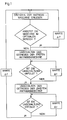
- ein Ablaufdiagramm der Fahrsteuerung in einer einfachen Version ohne Kompensation der durch die Umschaltung verursachten Zugkraftreduktion
Abbildung 2- die erfindungsgemäße Steuereinrichtung zur Fahrsteuerung für ein Fahrzeug mit mehreren Antriebsmaschinen.
- illustration 1
- a flow diagram of the driving control in a simple version without compensation for the reduction in traction caused by the switch
- Figure 2
- the control device according to the invention for driving control for a vehicle with a plurality of drive machines.
Gemäß dem erfindungsgemäßen Verfahren wird zunächst ermittelt, ob die Antriebsmaschine, in vorliegendem Fall die als motorbetriebene Transversalflußmaschine im optimalen Bereich betreffend den Wirkungsgrad arbeitet.According to the method according to the invention, it is first determined whether the drive machine, in the present case the motor-operated transverse flux machine, is operating in the optimum range with regard to the efficiency.
Da der Wirkungsgrad der elektrischen Maschine im wesentlichen davon abhängt, daß die Antriebsmaschine in einem bestimmten Drehzahlbereich betrieben wird, stellt eine nach dem TFM-Motor aufgenommene Drehzahl ein direktes Maß für den Wirkungsgrad der Maschine dar.Since the efficiency of the electrical machine essentially depends on the fact that the drive machine is operated in a certain speed range, a speed recorded after the TFM motor is a direct measure of the efficiency of the machine.
Daher ist in der vorliegend dargestellten sehr einfachen Ausführungsform in einem ersten Schritt des erfindungsgemäßen Verfahrens vorgesehen, den aktuellen Drehzahlwert der elektrischen Maschine in periodischen Abständen ΔT in einen Speicherbereich der Steuereinheit einzulesen. Durch Vergleich mit den in der Steuereinheit abgelegten Kennlinien wird ermittelt, ob die Antriebsmaschine in optimalem Bereich betreffend den Wirkungsgrad arbeitet.Therefore, in the very simple embodiment shown here, it is provided in a first step of the method according to the invention to read the current speed value of the electrical machine into a memory area of the control unit at periodic intervals ΔT. A comparison with the characteristic curves stored in the control unit determines whether the drive machine is operating in an optimal range with regard to the efficiency.
Selbstverständlich können in einer weitergebildeten Ausführungsform auch andere für den Wirkungsgrad der elektrischen Maschine charakteristischen Größen noch aufgenommen, in den Speicherbereich eingelesen und mit den Kennlinien in Bezug auf einen optimalen Wirkungsgrad verglichen werden.Of course, in a further developed embodiment, other quantities characteristic of the efficiency of the electrical machine can also be recorded, read into the memory area and compared with the characteristic curves in relation to an optimal efficiency.
Wird bei der Abfrage, ob die Antriebsmaschine im optimalen Bereich arbeitet, festgestellt, daß dies der Fall ist, so wird nach einer Einlesewartezeit ΔT, die im Bereich von 1 ms bis 1 s liegen kann, ein neuer Wert eingelesen. Arbeitet die Antriebsmaschine nicht im optimalen Bereich, so soll das nachgeschaltete Getriebe umgeschaltet werden. Auf diese Art und Weise ist es möglich, die Bereich des otpimalen Wirkungsgrades der elektrischen Maschine in einen anderen Abtriebsdrehzahlbereich zu transformieren. Beispielsweise kann bei einen zweistufigen Getriebe der Bereich des optimalen Wirkungsgrades dann zweimal durchfahren werden, wodurch der Gesamtwirkungsgrad angehoben wird. Da während der Umschaltung des Getriebes, insbesondere wenn die einfach aufgebauten Klauengetriebe verwendet werden, die nur während der Schaltung Hilfsenergie benötigen, eine Zugkraftunterbrechung auftritt, ist gemäß der Erfindung vorgesehen, die den verschiedenen Antriebsmaschinen zugeordneten Getriebe nicht gleichzeitig, sondern nacheinander zu schalten. In dem vorliegend dargestellten Ausführungsbeispiel wird dies dadurch erreicht, daß zunächst das Getriebe der ersten Antriebsmaschine umgeschaltet wird. In der dargestellten Ausführungsform wird abgefragt, ob die Umschaltung erfolgt ist, dies kann beispielsweise dadurch geschehen, daß wiederum der aktuelle Drehzahlwert der Antriebsmaschine in periodischen Abfragezeitintervallen Δt bestimmt wird. Ist die Umschaltung noch nicht erfolgt, so wird nach Δt nochmals die Abfrage durchgeführt. Ist dagegen die Umschaltung des Getriebes der ersten Antriebsmaschine erfolgt, so wird nachfolgend die Umschaltung des Getriebes der zweiten Antriebsmaschine vorgenommen. In einer Weiterbildung der Erfindung kann vorgesehen sein, daß während die Umschaltung des Getriebes der ersten Antriebsmaschine erfolgt, kurzzeitig die Leistung der zweiten Antriebsmaschine in dem Maß erhöht wird, in dem die Zugkraft bei der Umschaltung des Getriebes der ersten Antriebsmaschine vermindert wird. Durch diese Maßnahme ist es möglich, die Zugkraftreduktion beim Schalten des Getriebes durch die restlichen Antriebsmaschinen auszugleichen und somit den Ausfall einer Antriebseinheit während des Schaltvorgangs. Eine Zugkraftreduktion würde in einem solchen Fall überhaupt nicht auftreten.If the query as to whether the drive machine is operating in the optimal range determines that this is the case, a new value is read in after a read-in waiting time ΔT, which can be in the range from 1 ms to 1 s. If the prime mover does not work in the optimal range, the downstream transmission should be switched over. In this way, it is possible to transform the range of the optimal efficiency of the electrical machine into another output speed range. For example, in the case of a two-stage gearbox, the range of optimal efficiency can then be passed through twice, which increases the overall efficiency becomes. Since an interruption in tractive force occurs during the changeover of the transmission, particularly when the simply constructed claw transmissions are used, which only require auxiliary energy during the shift, the invention provides that the transmissions assigned to the different drive machines are not switched simultaneously but in succession. In the exemplary embodiment shown here, this is achieved by first switching the transmission of the first drive machine. In the embodiment shown, a query is made as to whether the switchover has taken place, this can be done, for example, by again determining the current speed value of the drive machine at periodic query time intervals Δt. If the switchover has not yet taken place, the query is carried out again after Δt. If, on the other hand, the transmission of the first drive machine has been switched over, the transmission of the second drive machine is subsequently switched over. In a further development of the invention it can be provided that while the transmission of the first drive machine is being switched over, the power of the second drive machine is increased briefly to the extent that the tractive force is reduced when the transmission of the first drive machine is switched over. This measure makes it possible to compensate for the reduction in tractive force when the transmission is shifted by the remaining drive machines and thus the failure of a drive unit during the shifting process. In such a case, a reduction in traction would not occur at all.
Auch bei der Umschaltung des Getriebes der zweiten Antriebsmaschine ist eine Abfrage nachgeschaltet, mit der überwacht wird, ob die Umschaltung abgeschlossen ist oder nicht. Ist auch die Umschaltung der zweiten Antriebsmaschine beendet, so wird nach einer Einlesewartezeit ΔT erneut die Drehzahl der Antriebsmaschine eingelesen und das in Abbildung 1 dargestellte Steuerungsverfahren wiederholt.When the gearbox of the second drive machine is switched over, an interrogation is also carried out to monitor whether the switchover has been completed or not. If the switchover of the second drive machine has also ended, the speed of the drive machine is read in again after a read-in waiting time ΔT and the control process shown in FIG. 1 is repeated.
Für die Abfolge der Umschaltung der Getriebe der unterschiedlichen Antriebsmaschinen ist es möglich, verschiedene Konzepte vorzusehen.It is possible to provide different concepts for the sequence of switching the gears of the different drive machines.
Allen Ausführungsformen bzw. Konzepten ist jedoch gemeinsam, daß eine Umschaltung des nachfolgenden Getriebes erst erfolgt, wenn der Umschaltvorgang des ersten Getriebes abgeschlossen ist.All embodiments or concepts have in common, however, that the subsequent transmission is only switched over when the switching operation of the first transmission has been completed.
Beispielsweise kann der Vorderachse eine Antriebsmaschine mit Getriebe und der Hinterachse eine ebensolche zugeordnet sein. Dann ist möglich, zunächst das Getriebe der Antriebsmaschine der Vorderachse umzuschalten und anschließend das Getriebe der Hinterachse oder umgekehrt.For example, the front axle can be assigned a drive machine with a transmission and the rear axle can be assigned the same. It is then possible to first switch the gearbox of the front axle drive machine and then the gearbox of the rear axle or vice versa.
Es kann aber auch vorgesehen sein, daß jedem Rad einer Achse eine eigene Antriebsmaschine mit nachgeschaltetem Getriebe zugeordnet ist. Dann ergeben sich folgende Möglichkeiten der Schaltabfolge: Zunächst wird das der in Fahrtrichtung gesehen linken Antriebsmaschine der Vorderachse zugeordnete Getriebe geschaltet und anschließend das der Antriebsmaschine des rechten Rades in Fahrtrichtung gesehen. Anschließend findet der Umschaltvorgang an der Hinterachse analog zu dem der Vorderachse statt. Selbstverständlich ist es möglich, zunächst die Getriebe der Hinterachse umzuschalten und anschließend die der Vorderachse. In einer besonders bevorzugten Ausführungsform ist eine Schaltung über Kreuz vorgesehen. Das heißt, daß zunächst das Getriebe eines Rades der Vorderachse umgeschaltet wird, beispielsweise das dem linken Rad in Fahrtrichtung gesehene zugeordnete, und anschließend das Getriebe des rechten Rades der Hinterachse. Die Umschaltung der beiden weiteren Antriebsmotoren findet ebenfalls wieder über Kreuz nachfolgend statt. Eine derartige Über-Kreuz-Schaltung hat beispielsweise den Vorteil, daß ein ungleiches Ziehen des Fahrzeuges vermieden wird. Für den Fachmann ergeben sich aus den bislang dargestellten Beispielsfällen die restlichen Möglichkeiten der nacheinander ausgeführten Umschaltung auf zwanglose Art und Weise.However, it can also be provided that each wheel of an axle is assigned its own drive machine with a downstream transmission. The following switching sequence options then result: First, the gearbox assigned to the drive machine on the left in the direction of travel of the front axle is shifted and then that of the drive machine in the right wheel is seen in the direction of travel. The switching process on the rear axle then takes place analogously to that of the front axle. Of course, it is possible to first switch the transmission of the rear axle and then that of the front axle. In a particularly preferred embodiment, a cross connection is provided. This means that first the gear of a wheel of the front axle is switched, for example that assigned to the left wheel as seen in the direction of travel, and then the gear of the right wheel of the rear axle. The switchover of the other two drive motors also takes place crosswise again. Such a crossover circuit has the advantage, for example, that uneven pulling of the vehicle is avoided. For the person skilled in the art, the remaining possibilities of switching over in succession arise in an informal manner from the example cases described so far.
Neben dem erfindungsgemäßen Verfahren wird auch eine Fahrsteuereinrichtung zur Durchführung insbesondere dieses Verfahrens angegeben. Eine derartige, beispielhafte Vorrichtung zeigt Abbildung 2.In addition to the method according to the invention, a driving control device for performing this method is also specified. Such an exemplary device is shown in Figure 2.
In Abbildung 1 sind die den jeweiligen Rädern 5,6 einer Achse, die die Vorderachse oder Hinterachse sein kann, zugeordneten Antriebsmaschinen 1, 2 und die nachgeschalteten Getriebe 3, 4 dargestellt. Bei den nachgeschalteten Getrieben handelt es sich um mehrstufige, vorzugsweise zweistufige Getriebe, die synchronisiert oder unsynchronisiert ausgeführt sein können. Besonders vorteilhaft ist es, als Getriebe zweistufige Klauengetriebe (siehe hierzu beispielsweise Dubbel, Taschenbuch für den Maschinenbau, 1996, Seiten G 63 bis G 195) vorzusehen, die sich insbesondere durch einen einfachen Getriebeaufbau auszeichnen. Desweiteren benötigen solche Getriebe nur während der Schaltung Hilfsenergie, wodurch der Wirkungsgradverlust durch das Getriebe selbst gering ist. Aufwendiger wäre es, andere Getriebearten vorzusehen, die insbesondere darunter leiden, daß durch das Getriebe ein ständiger Wirkungsgradverlust auftritt, was natürlich den Gesamtwirkungsgrad der Antriebsmaschinen für das Fahrzeug verringert. Die jeweilige Antriebseinheit aus Antriebsmaschine, die vorliegend eine Transversalflußmaschine ist, und Getriebe sind je einem Rad zugeordnet. So ist die Transversalflußmaschine 1 und das nachgeschaltete Getriebe 3 dem in Fahrtrichtung gesehenen linken Rad 5, und in analoger Weise die Transversalflußmaschine 2 und das Getriebe 4 dem in Fahrtrichtung gesehenen rechten Rad 6 zugeordnet. Sowohl die Transversalfluß-Motoren 1, 2 als auch die Getriebe 3, 4 sind über Steuerleitungen 7, 8, 9, 10 mit einer Steuereinrichtung 20, die vorzugsweise ein Microcomputer mit entsprechenden Ausgängen ist, angeschlossen. Zwischen Transversalflußmaschine und nachfolgendem Getriebe sind Meßleitungen 21, 22 vorgesehen, die ebenfalls an die Steuereinrichtung angeschaltet sind. Über die Meßleitungen 21, 22 werden Meßsignale, die mittels Aufnehmern bzw. Sensoren von der Transversalflußmaschine abgenommen werden, an die Steuereinrichtung übermittelt. Bei den Aufnehmern bzw. Sensoren kann es sich in einer Ausführungsform um Drehzahlaufnehmern handeln, mit der die momentane Drehzahl der Transversalflußmaschine festgestellt wird. Mit Hilfe der Steuerleitungen 7, 8, 9, 10 werden Steuersignale sowohl an die Transversalflußmaschine als auch das nachgeordnete Getriebe übertragen. Über die Steuerleitungen 9, 10 können beispielsweise Signale an einen Aktuator übermittelt werden, der das Getriebe betätigt, das heißt im vorliegenden Fall umschaltet. Denkbar sind als Aktuatoren handelsübliche Magnetventile, wie sie für die Getriebesteuerung Verwendung finden. Die an die Transversalflußmaschine angeschlossenen Steuerleitungen 7, 8 ermöglichen es, diese anzusteuern, beispielsweise die Leistungsabgabe kurzfristig zu erhöhen, so lange das Getriebe der anderen Maschine umgeschaltet wird, damit eine Zugkraftunterbrechung zu kommentieren.Figure 1 shows the
Mit der vorliegenden Erfindung wird somit erstmals ein Verfahren und eine Vorrichtung für den Betrieb eines Fahrzeuges mit mehreren Antriebsmaschinen angegeben, bei dem es möglich ist, durch den Einsatz einfach aufgebauter Getriebe den Gesamtwirkungsgrad zu steigern.The present invention thus for the first time specifies a method and a device for operating a vehicle with a plurality of drive machines, in which it is possible to increase the overall efficiency by using simply constructed gears.
Claims (11)
die elektrische Maschine eine Transversalflußmaschine ist.A method according to claim 1, characterized in that
the electrical machine is a transverse flux machine.
zunächst das Getriebe der Antriebsmaschine des linken Rades in Fahrtrichtung gesehen der Vorder- bzw. Hinterachse geschaltet wird und anschließend das Getriebe der Antriebsmaschine des rechten Rades in Fahrtrichtung gesehen der Vorder- bzw. Hinterachse geschaltet wird, oder zunächst das Getriebe der Antriebsmaschine des rechten Rades in Fahrtrichtung gesehen der Vorder- bzw. Hinterachse geschaltet wird und anschließend das Getriebe der Antriebsmaschine des linken Rades in Fahrtrichtung gesehen der Vorder- bzw. Hinterachse geschaltet wird.Method according to one of claims 1 to 2, characterized in that
First the gear of the drive unit of the left wheel viewed in the direction of travel of the front or rear axle is switched and then the transmission of the drive engine of the right wheel viewed in the direction of travel the front or rear axle is switched, or first the gear of the drive unit of the right wheel in Driving direction seen the front or rear axle is switched and then the transmission of the drive machine of the left wheel is viewed in the direction of travel of the front or rear axle is switched.
gekennzeichnet, daß
beim Schalten zum Ausgleich der Zugkraftreduktion durch den Schaltvorgang die übrigen Antriebsmaschinen kurzzeitig höher belastet werden, derart, daß überhaupt keine Zugkraftreduktion auftritt.Method according to one of claims 1 to 4, characterized
characterized in that
when shifting to compensate for the reduction in traction through the switching process, the other drive machines are temporarily subjected to higher loads such that there is no reduction in traction at all.
dadurch gekennzeichnet, daß
characterized in that
die elektrische Maschine eine Transversalflußmaschine ist.Control device according to claim 6, characterized in that
the electrical machine is a transverse flux machine.
die den Antriebsmaschinen nachgeordneten Getriebe zweistufige Getriebe sind.Control device according to one of claims 6 to 7, characterized in that
the transmissions downstream of the drive machines are two-stage transmissions.
die Getriebe Klauengetriebe sind.Control device according to one of claims 6 to 8, characterized in that
the gearboxes are dog gearboxes.
die Getriebe synchronisiert sind.Control device according to one of claims 6 to 9, characterized in that
the gears are synchronized.
die Getriebe unsynchronisiert sind.Control device according to one of claims 6 to 10, characterized in that
the gears are out of synchronization.
Applications Claiming Priority (2)
| Application Number | Priority Date | Filing Date | Title |
|---|---|---|---|
| DE19619321A DE19619321C2 (en) | 1996-05-14 | 1996-05-14 | Method for operating a vehicle with several electric drive machines |
| DE19619321 | 1996-05-14 |
Publications (3)
| Publication Number | Publication Date |
|---|---|
| EP0807772A2 true EP0807772A2 (en) | 1997-11-19 |
| EP0807772A3 EP0807772A3 (en) | 1999-06-09 |
| EP0807772B1 EP0807772B1 (en) | 2002-12-04 |
Family
ID=7794226
Family Applications (1)
| Application Number | Title | Priority Date | Filing Date |
|---|---|---|---|
| EP97107057A Expired - Lifetime EP0807772B1 (en) | 1996-05-14 | 1997-04-29 | Method for driving a vehicle with plural prime movers |
Country Status (3)
| Country | Link |
|---|---|
| US (1) | US5879265A (en) |
| EP (1) | EP0807772B1 (en) |
| DE (2) | DE19619321C2 (en) |
Cited By (3)
| Publication number | Priority date | Publication date | Assignee | Title |
|---|---|---|---|---|
| EP1382476A1 (en) * | 2002-07-15 | 2004-01-21 | Conception et Développement Michelin S.A. | Drive train with a shifting mechanism incorporated in a wheel and shifting method thereof |
| CN104827897A (en) * | 2014-02-07 | 2015-08-12 | 威士多公司 | Electromechanical drive for a working machine |
| WO2019092028A1 (en) * | 2017-11-07 | 2019-05-16 | Robert Bosch Gmbh | Driving propulsion assembly for a machine |
Families Citing this family (69)
| Publication number | Priority date | Publication date | Assignee | Title |
|---|---|---|---|---|
| DE19932118C1 (en) * | 1999-07-09 | 2000-10-26 | Daimler Chrysler Ag | Multiple electric motor drive for motor vehicle has common drive output containing gearbox controlled by controller that selects gears for optimal efficiency |
| US7729831B2 (en) * | 1999-07-30 | 2010-06-01 | Oshkosh Corporation | Concrete placement vehicle control system and method |
| US6885920B2 (en) * | 1999-07-30 | 2005-04-26 | Oshkosh Truck Corporation | Control system and method for electric vehicle |
| US6757597B2 (en) * | 2001-01-31 | 2004-06-29 | Oshkosh Truck | A/C bus assembly for electronic traction vehicle |
| US6447423B1 (en) | 2000-07-31 | 2002-09-10 | Caterpillar Inc. | Method and apparatus for adjusting transmission ratio commands for a continuously variable transmission |
| DE10057092A1 (en) | 2000-11-17 | 2002-05-23 | Zahnradfabrik Friedrichshafen | Drive system for vehicle has left and right drive wheels, each driven by electric motor(s) and gearbox with mechanical, continuously adjustable gear unit(s) with bevel pulley pairs, belt element |
| US7277782B2 (en) * | 2001-01-31 | 2007-10-02 | Oshkosh Truck Corporation | Control system and method for electric vehicle |
| US7379797B2 (en) * | 2001-01-31 | 2008-05-27 | Oshkosh Truck Corporation | System and method for braking in an electric vehicle |
| FR2824782A1 (en) | 2001-05-17 | 2002-11-22 | Michelin Soc Tech | Tyre presenting machine giving access to inner and outer surfaces has support making contact solely with vertical toroid section of tyre |
| JP3744414B2 (en) * | 2001-11-29 | 2006-02-08 | トヨタ自動車株式会社 | Vehicle control device |
| US7302320B2 (en) * | 2001-12-21 | 2007-11-27 | Oshkosh Truck Corporation | Failure mode operation for an electric vehicle |
| US7254468B2 (en) * | 2001-12-21 | 2007-08-07 | Oshkosh Truck Corporation | Multi-network control system for a vehicle |
| US7520354B2 (en) * | 2002-05-02 | 2009-04-21 | Oshkosh Truck Corporation | Hybrid vehicle with combustion engine/electric motor drive |
| US6909959B2 (en) * | 2003-03-07 | 2005-06-21 | Stephen James Hallowell | Torque distribution systems and methods for wheeled vehicles |
| DE10316862A1 (en) * | 2003-04-11 | 2004-10-21 | Deere & Company, Moline | Drive system for vehicles |
| ATE372477T1 (en) | 2003-07-09 | 2007-09-15 | Michelin Rech Tech | METHOD FOR CHANGING GEARS OF A DRIVE TRAIN WHICH HAS A SHIFT MECHANISM FOR EACH DRIVE WHEEL |
| FR2857426A1 (en) * | 2003-07-09 | 2005-01-14 | Conception & Dev Michelin Sa | Drive wheel gear shifting control method, involves changing speed of rotation of motor for synchronizing it according to reduction of gear ratio to be engaged on maneuvered wheel, and engaging target ratio of gear on wheel |
| DE10347596B3 (en) * | 2003-10-14 | 2005-06-02 | Bayerische Motoren Werke Ag | Operating efficiency optimization method for automobile hybrid drive system with measurement of actual operating efficiency of each drive unit at each operating point and re-setting of operating point upon variation in monitored parameter |
| US7439711B2 (en) * | 2004-09-27 | 2008-10-21 | Oshkosh Corporation | Energy storage device including a status indicator |
| US20060112781A1 (en) * | 2004-11-30 | 2006-06-01 | Brian Kuras | Multi-motor/multi-range torque transmitting power system |
| DE102005019489A1 (en) * | 2005-04-27 | 2006-11-09 | Krauss-Maffei Wegmann Gmbh & Co. Kg | Four-wheel drive motor vehicle |
| DE102006006766A1 (en) * | 2006-02-13 | 2007-08-23 | Claas Selbstfahrende Erntemaschinen Gmbh | motor vehicle |
| DE102006014514A1 (en) * | 2006-03-24 | 2007-10-11 | Getrag Innovations Gmbh | Powertrain and manufacturing and installation process |
| US20070251742A1 (en) * | 2006-05-01 | 2007-11-01 | Adams Herbert L Iii | Vehicle with hybrid power train providing part-time all-wheel drive |
| US7364524B2 (en) * | 2006-05-01 | 2008-04-29 | American Axel & Manufacturing, Inc. | Driveline coupling for electric module |
| US8139109B2 (en) | 2006-06-19 | 2012-03-20 | Oshkosh Corporation | Vision system for an autonomous vehicle |
| US8947531B2 (en) | 2006-06-19 | 2015-02-03 | Oshkosh Corporation | Vehicle diagnostics based on information communicated between vehicles |
| DE102006058982B4 (en) * | 2006-12-14 | 2017-07-20 | Zf Friedrichshafen Ag | Method for switching at least two automated manual transmissions |
| US7973446B2 (en) * | 2007-05-09 | 2011-07-05 | Motor Excellence, Llc | Electrical devices having tape wound core laminate rotor or stator elements |
| JP2012508549A (en) | 2008-11-03 | 2012-04-05 | モーター エクセレンス, エルエルシー | Stator concept for lateral and / or commutated flux systems |
| DE102009002437B4 (en) * | 2009-04-16 | 2026-01-22 | Zf Friedrichshafen Ag | Switching procedure in a purely electrically powered vehicle |
| DK2548289T3 (en) | 2010-03-15 | 2020-02-17 | Motor Excellence Llc | TRANSITIONAL AND / OR COMMUTIONED PHASE SHIFTING SYSTEMS |
| CN102986115A (en) | 2010-03-15 | 2013-03-20 | 电扭矩机器股份有限公司 | Transverse and/or commutated flux systems for electric bicycles |
| EP2548288A1 (en) * | 2010-03-15 | 2013-01-23 | Motor Excellence, LLC | Transverse and/or commutated flux systems configured to provide reduced flux leakage, hysteresis loss reduction, and phase matching |
| US8337352B2 (en) | 2010-06-22 | 2012-12-25 | Oshkosh Corporation | Electromechanical variable transmission |
| CN103477538A (en) | 2010-11-17 | 2013-12-25 | 电动转矩机器公司 | Transverse and/or commutated flux systems having segmented stator laminations |
| US8952590B2 (en) | 2010-11-17 | 2015-02-10 | Electric Torque Machines Inc | Transverse and/or commutated flux systems having laminated and powdered metal portions |
| WO2012067895A2 (en) | 2010-11-17 | 2012-05-24 | Motor Excellence, Llc | Transverse and/or commutated flux system coil concepts |
| DE102012209920A1 (en) * | 2012-06-13 | 2013-12-19 | Siemens Aktiengesellschaft | Vehicle e.g. hybrid electric vehicle for driving in e.g. city traffic, has two electromotors for driving shaft by gear box, and control device for distributing power to shaft based on power available on electromotors |
| US9132736B1 (en) | 2013-03-14 | 2015-09-15 | Oshkosh Defense, Llc | Methods, systems, and vehicles with electromechanical variable transmission |
| US9650032B2 (en) | 2015-02-17 | 2017-05-16 | Oshkosh Corporation | Multi-mode electromechanical variable transmission |
| US9651120B2 (en) | 2015-02-17 | 2017-05-16 | Oshkosh Corporation | Multi-mode electromechanical variable transmission |
| US12078231B2 (en) | 2015-02-17 | 2024-09-03 | Oshkosh Corporation | Inline electromechanical variable transmission system |
| US10421350B2 (en) | 2015-10-20 | 2019-09-24 | Oshkosh Corporation | Inline electromechanical variable transmission system |
| US10982736B2 (en) | 2015-02-17 | 2021-04-20 | Oshkosh Corporation | Multi-mode electromechanical variable transmission |
| US10584775B2 (en) | 2015-02-17 | 2020-03-10 | Oshkosh Corporation | Inline electromechanical variable transmission system |
| US10578195B2 (en) | 2015-02-17 | 2020-03-03 | Oshkosh Corporation | Inline electromechanical variable transmission system |
| US11701959B2 (en) | 2015-02-17 | 2023-07-18 | Oshkosh Corporation | Inline electromechanical variable transmission system |
| US9656659B2 (en) | 2015-02-17 | 2017-05-23 | Oshkosh Corporation | Multi-mode electromechanical variable transmission |
| US9463697B1 (en) * | 2015-05-28 | 2016-10-11 | Atieva, Inc. | Dual data rate traction control system for a two wheel drive electric vehicle |
| US9469199B1 (en) * | 2015-05-28 | 2016-10-18 | Atieva, Inc. | Dual data rate traction control system for a four wheel drive electric vehicle |
| US10207751B2 (en) | 2016-05-09 | 2019-02-19 | Nikola Motor Company Llc | Motor gearbox assembly |
| US11001129B2 (en) | 2015-12-30 | 2021-05-11 | Nikola Corporation | Cargo door for semi-truck |
| US10981609B2 (en) | 2015-12-30 | 2021-04-20 | Nikola Corporation | Systems, methods, and devices for an automobile door or window |
| US10266025B2 (en) | 2016-05-06 | 2019-04-23 | Arvinmeritor Technology, Llc | Suspension module having an air spring pedestal |
| US10435075B2 (en) | 2016-05-06 | 2019-10-08 | Arvinmeritor Technology, Llc | Suspension module having a subframe assembly |
| CN109996978B (en) | 2016-11-25 | 2021-05-04 | 沃尔沃卡车集团 | drive unit for vehicles |
| US10272899B2 (en) * | 2017-08-01 | 2019-04-30 | Proterra Inc. | Controlling the powertrain of a vehicle |
| US10926596B2 (en) | 2019-02-28 | 2021-02-23 | Arvinmeritor Technology, Llc | Suspension system |
| US10814917B2 (en) | 2019-03-04 | 2020-10-27 | Arvinmeritor Technology, Llc | Assembly having a skid plate module |
| US10913321B2 (en) | 2019-03-04 | 2021-02-09 | Arvinmeritor Technology, Llc | Suspension system |
| DE102019214986A1 (en) | 2019-09-30 | 2021-04-01 | Zf Friedrichshafen Ag | Drive axle of an electric vehicle and powershift process |
| DE102019216562A1 (en) * | 2019-10-28 | 2021-04-29 | Zf Friedrichshafen Ag | Drive arrangement of an electric vehicle and load shifting method |
| DE102021122090B4 (en) | 2021-08-26 | 2026-01-29 | Audi Aktiengesellschaft | Electrical circuit arrangement, motor vehicle and method for operating an electrical circuit arrangement |
| DE102022203097A1 (en) | 2022-03-30 | 2023-10-05 | Zf Friedrichshafen Ag | Drive unit for a drive axle of a vehicle |
| DE102022203098A1 (en) | 2022-03-30 | 2023-10-05 | Zf Friedrichshafen Ag | Drive unit for a drive axle of a vehicle |
| FI131798B1 (en) * | 2022-08-09 | 2025-12-03 | Ponsse Oyj | Work machine and method in work machine power transmission |
| DE102022209050A1 (en) | 2022-08-31 | 2024-02-29 | Zf Friedrichshafen Ag | Method and control device for operating a drive train of a vehicle |
| DE102023212673A1 (en) | 2023-12-14 | 2025-06-18 | Zf Friedrichshafen Ag | Motor vehicle transmission for an at least partially electrically powered motor vehicle |
Citations (1)
| Publication number | Priority date | Publication date | Assignee | Title |
|---|---|---|---|---|
| DE3927453C2 (en) | 1989-08-19 | 1991-05-23 | Herbert Prof. Dr.-Ing. 3300 Braunschweig De Weh |
Family Cites Families (8)
| Publication number | Priority date | Publication date | Assignee | Title |
|---|---|---|---|---|
| DE1655194C3 (en) * | 1967-12-07 | 1979-04-26 | Robert Bosch Gmbh, 7000 Stuttgart | Automatic switching device for motor vehicles with at least two independent drive groups |
| JPS5266224A (en) * | 1975-11-29 | 1977-06-01 | Agency Of Ind Science & Technol | Automatic transmission control device for elecric car |
| JPS52155717A (en) * | 1976-06-18 | 1977-12-24 | Agency Of Ind Science & Technol | Automatic transmission system for electric vehicle |
| US4766967A (en) * | 1985-12-27 | 1988-08-30 | Eaton Corporation | Oscillation control system for electric motor drive |
| DE3705089A1 (en) * | 1987-02-13 | 1988-08-25 | Weh Herbert | TRANSVERSAL FLOWING MACHINE IN COLLECTOR ARRANGEMENT |
| JPH05161216A (en) * | 1991-12-05 | 1993-06-25 | Honda Motor Co Ltd | Shift control device for electric vehicle |
| JP3200901B2 (en) * | 1991-12-20 | 2001-08-20 | 株式会社日立製作所 | Electric vehicle drive |
| JP3441162B2 (en) * | 1994-05-27 | 2003-08-25 | 本田技研工業株式会社 | Shift control method for electric vehicle |
-
1996
- 1996-05-14 DE DE19619321A patent/DE19619321C2/en not_active Expired - Fee Related
-
1997
- 1997-04-29 DE DE59708862T patent/DE59708862D1/en not_active Expired - Lifetime
- 1997-04-29 EP EP97107057A patent/EP0807772B1/en not_active Expired - Lifetime
- 1997-05-14 US US08/856,107 patent/US5879265A/en not_active Expired - Fee Related
Patent Citations (1)
| Publication number | Priority date | Publication date | Assignee | Title |
|---|---|---|---|---|
| DE3927453C2 (en) | 1989-08-19 | 1991-05-23 | Herbert Prof. Dr.-Ing. 3300 Braunschweig De Weh |
Non-Patent Citations (2)
| Title |
|---|
| B.WUEST, R.MUELLER, A.LANGE: "EIN ELEKTRISCHER EINZELRADANTRIEB FUER CITYBUSSE DER ZUKUNFT", DER NAHVERKEHR, no. 6, June 1994 (1994-06-01), DUESSELDORF |
| DUBBEL: "TASCHENBUCH FUER DEN MASCHINENBAU", pages: G 63 - G 195 |
Cited By (5)
| Publication number | Priority date | Publication date | Assignee | Title |
|---|---|---|---|---|
| EP1382476A1 (en) * | 2002-07-15 | 2004-01-21 | Conception et Développement Michelin S.A. | Drive train with a shifting mechanism incorporated in a wheel and shifting method thereof |
| CN1313298C (en) * | 2002-07-15 | 2007-05-02 | 米其林创意开发股份有限公司 | Haulage chain of variable speed mechanism integrated in wheel |
| CN104827897A (en) * | 2014-02-07 | 2015-08-12 | 威士多公司 | Electromechanical drive for a working machine |
| CN104827897B (en) * | 2014-02-07 | 2019-04-16 | 丹佛斯移动电气化公司 | Electromechanical driver for working machine |
| WO2019092028A1 (en) * | 2017-11-07 | 2019-05-16 | Robert Bosch Gmbh | Driving propulsion assembly for a machine |
Also Published As
| Publication number | Publication date |
|---|---|
| EP0807772A3 (en) | 1999-06-09 |
| EP0807772B1 (en) | 2002-12-04 |
| DE19619321C2 (en) | 1998-07-09 |
| DE19619321A1 (en) | 1997-11-20 |
| US5879265A (en) | 1999-03-09 |
| DE59708862D1 (en) | 2003-01-16 |
Similar Documents
| Publication | Publication Date | Title |
|---|---|---|
| DE19619321C2 (en) | Method for operating a vehicle with several electric drive machines | |
| EP1954542B1 (en) | Hybrid drive for vehicles and method for controlling a transmission for a hybrid drive | |
| EP2323862B1 (en) | Method and device for operating a hybrid drive for a vehicle | |
| DE19955312B4 (en) | Drive system for industrial trucks | |
| DE19954544B4 (en) | Automotive drive | |
| DE102019218239A1 (en) | Drive unit for an electrically driven axle and method for operating the drive unit | |
| EP2411255B1 (en) | Method for controlling a railway vehicle | |
| DE19919454C2 (en) | Vehicle drive device | |
| EP0796758B1 (en) | Traction unit of a vehicle, especially for city buses | |
| DE102020000449A1 (en) | Transmission with power take-off | |
| DE19955313C2 (en) | Drive system for industrial trucks | |
| DE19729382A1 (en) | The electric drive arrangement with a starting torque converter | |
| EP0312018A2 (en) | Method for the change of place of motor vehicles through repeated forward and backward impulses | |
| EP1306255A2 (en) | Diesel-electric vehicle drive apparatus with torque converter transmission unit | |
| DE102019206459A1 (en) | Snowcat | |
| DE102020000462A1 (en) | Modular transmission kit for a motor vehicle | |
| DE102018120026A1 (en) | Method for operating a motor vehicle with an electric drive | |
| EP1055547B1 (en) | Control system for the drive components of a railway vehicle | |
| DE3719812C2 (en) | Control system with an actuator for regulating the performance of an internal combustion engine with a subordinate manual transmission | |
| DE19754932A1 (en) | Electric braking resistor assembly for electric drive systems | |
| DE102020001795B3 (en) | Electric motor drive for a motor vehicle | |
| EP1434701B1 (en) | Electric motor coupled to an internal combustion engine in a motor vehicle | |
| DE10004051A1 (en) | Process for providing services for auxiliary consumers in electrical drive systems and electrical drive system | |
| DE3842631A1 (en) | DRIVE FOR A MOTOR VEHICLE | |
| DE102006058982B4 (en) | Method for switching at least two automated manual transmissions |
Legal Events
| Date | Code | Title | Description |
|---|---|---|---|
| PUAI | Public reference made under article 153(3) epc to a published international application that has entered the european phase |
Free format text: ORIGINAL CODE: 0009012 |
|
| AK | Designated contracting states |
Kind code of ref document: A2 Designated state(s): DE FR GB IT SE |
|
| PUAL | Search report despatched |
Free format text: ORIGINAL CODE: 0009013 |
|
| AK | Designated contracting states |
Kind code of ref document: A3 Designated state(s): DE FR GB IT SE |
|
| 17P | Request for examination filed |
Effective date: 19990518 |
|
| GRAG | Despatch of communication of intention to grant |
Free format text: ORIGINAL CODE: EPIDOS AGRA |
|
| GRAG | Despatch of communication of intention to grant |
Free format text: ORIGINAL CODE: EPIDOS AGRA |
|
| GRAH | Despatch of communication of intention to grant a patent |
Free format text: ORIGINAL CODE: EPIDOS IGRA |
|
| 17Q | First examination report despatched |
Effective date: 20020605 |
|
| GRAH | Despatch of communication of intention to grant a patent |
Free format text: ORIGINAL CODE: EPIDOS IGRA |
|
| GRAA | (expected) grant |
Free format text: ORIGINAL CODE: 0009210 |
|
| AK | Designated contracting states |
Kind code of ref document: B1 Designated state(s): DE FR GB IT SE |
|
| REG | Reference to a national code |
Ref country code: GB Ref legal event code: FG4D Free format text: NOT ENGLISH |
|
| GBT | Gb: translation of ep patent filed (gb section 77(6)(a)/1977) |
Effective date: 20021204 |
|
| REF | Corresponds to: |
Ref document number: 59708862 Country of ref document: DE Date of ref document: 20030116 |
|
| ET | Fr: translation filed | ||
| PLBE | No opposition filed within time limit |
Free format text: ORIGINAL CODE: 0009261 |
|
| STAA | Information on the status of an ep patent application or granted ep patent |
Free format text: STATUS: NO OPPOSITION FILED WITHIN TIME LIMIT |
|
| 26N | No opposition filed |
Effective date: 20030905 |
|
| PGFP | Annual fee paid to national office [announced via postgrant information from national office to epo] |
Ref country code: SE Payment date: 20070416 Year of fee payment: 11 |
|
| PGFP | Annual fee paid to national office [announced via postgrant information from national office to epo] |
Ref country code: GB Payment date: 20070411 Year of fee payment: 11 |
|
| PGFP | Annual fee paid to national office [announced via postgrant information from national office to epo] |
Ref country code: IT Payment date: 20070627 Year of fee payment: 11 |
|
| PGFP | Annual fee paid to national office [announced via postgrant information from national office to epo] |
Ref country code: FR Payment date: 20070413 Year of fee payment: 11 |
|
| EUG | Se: european patent has lapsed | ||
| GBPC | Gb: european patent ceased through non-payment of renewal fee |
Effective date: 20080429 |
|
| REG | Reference to a national code |
Ref country code: FR Ref legal event code: ST Effective date: 20081231 |
|
| PG25 | Lapsed in a contracting state [announced via postgrant information from national office to epo] |
Ref country code: FR Free format text: LAPSE BECAUSE OF NON-PAYMENT OF DUE FEES Effective date: 20080430 |
|
| PG25 | Lapsed in a contracting state [announced via postgrant information from national office to epo] |
Ref country code: GB Free format text: LAPSE BECAUSE OF NON-PAYMENT OF DUE FEES Effective date: 20080429 |
|
| PG25 | Lapsed in a contracting state [announced via postgrant information from national office to epo] |
Ref country code: IT Free format text: LAPSE BECAUSE OF NON-PAYMENT OF DUE FEES Effective date: 20080429 |
|
| PG25 | Lapsed in a contracting state [announced via postgrant information from national office to epo] |
Ref country code: SE Free format text: LAPSE BECAUSE OF NON-PAYMENT OF DUE FEES Effective date: 20080430 |
|
| PGFP | Annual fee paid to national office [announced via postgrant information from national office to epo] |
Ref country code: DE Payment date: 20120509 Year of fee payment: 16 |
|
| PG25 | Lapsed in a contracting state [announced via postgrant information from national office to epo] |
Ref country code: DE Free format text: LAPSE BECAUSE OF NON-PAYMENT OF DUE FEES Effective date: 20131101 |
|
| REG | Reference to a national code |
Ref country code: DE Ref legal event code: R119 Ref document number: 59708862 Country of ref document: DE Effective date: 20131101 |