EP0807754A2 - Dispositif de traitement de carburant dérivé d'huile minérale ou de plantes - Google Patents
Dispositif de traitement de carburant dérivé d'huile minérale ou de plantes Download PDFInfo
- Publication number
- EP0807754A2 EP0807754A2 EP96117918A EP96117918A EP0807754A2 EP 0807754 A2 EP0807754 A2 EP 0807754A2 EP 96117918 A EP96117918 A EP 96117918A EP 96117918 A EP96117918 A EP 96117918A EP 0807754 A2 EP0807754 A2 EP 0807754A2
- Authority
- EP
- European Patent Office
- Prior art keywords
- reactor
- fuel
- tin
- copper
- catalyst
- Prior art date
- Legal status (The legal status is an assumption and is not a legal conclusion. Google has not performed a legal analysis and makes no representation as to the accuracy of the status listed.)
- Granted
Links
- 239000000446 fuel Substances 0.000 title claims abstract description 50
- 239000002480 mineral oil Substances 0.000 title claims abstract description 4
- 235000010446 mineral oil Nutrition 0.000 title claims description 3
- 238000010438 heat treatment Methods 0.000 claims abstract description 42
- RYGMFSIKBFXOCR-UHFFFAOYSA-N Copper Chemical compound [Cu] RYGMFSIKBFXOCR-UHFFFAOYSA-N 0.000 claims abstract description 22
- 229910052802 copper Inorganic materials 0.000 claims abstract description 19
- 239000010949 copper Substances 0.000 claims abstract description 19
- 229910001128 Sn alloy Inorganic materials 0.000 claims abstract description 15
- 239000003054 catalyst Substances 0.000 claims description 25
- ATJFFYVFTNAWJD-UHFFFAOYSA-N Tin Chemical compound [Sn] ATJFFYVFTNAWJD-UHFFFAOYSA-N 0.000 claims description 18
- 229910045601 alloy Inorganic materials 0.000 claims description 9
- 239000000956 alloy Substances 0.000 claims description 9
- 239000000463 material Substances 0.000 claims description 7
- 238000011144 upstream manufacturing Methods 0.000 claims description 7
- 239000002283 diesel fuel Substances 0.000 claims description 5
- 229910000597 tin-copper alloy Inorganic materials 0.000 claims description 5
- QPLDLSVMHZLSFG-UHFFFAOYSA-N Copper oxide Chemical compound [Cu]=O QPLDLSVMHZLSFG-UHFFFAOYSA-N 0.000 claims description 4
- 239000005751 Copper oxide Substances 0.000 claims description 4
- 230000003197 catalytic effect Effects 0.000 claims description 4
- 229910000431 copper oxide Inorganic materials 0.000 claims description 4
- 238000007789 sealing Methods 0.000 claims description 4
- 229910001887 tin oxide Inorganic materials 0.000 claims description 4
- 229910052878 cordierite Inorganic materials 0.000 claims description 3
- JSKIRARMQDRGJZ-UHFFFAOYSA-N dimagnesium dioxido-bis[(1-oxido-3-oxo-2,4,6,8,9-pentaoxa-1,3-disila-5,7-dialuminabicyclo[3.3.1]nonan-7-yl)oxy]silane Chemical compound [Mg++].[Mg++].[O-][Si]([O-])(O[Al]1O[Al]2O[Si](=O)O[Si]([O-])(O1)O2)O[Al]1O[Al]2O[Si](=O)O[Si]([O-])(O1)O2 JSKIRARMQDRGJZ-UHFFFAOYSA-N 0.000 claims description 3
- 238000002347 injection Methods 0.000 claims description 3
- 239000007924 injection Substances 0.000 claims description 3
- 239000002344 surface layer Substances 0.000 claims description 3
- XOLBLPGZBRYERU-UHFFFAOYSA-N tin dioxide Chemical compound O=[Sn]=O XOLBLPGZBRYERU-UHFFFAOYSA-N 0.000 claims description 3
- 229910002254 LaCoO3 Inorganic materials 0.000 claims description 2
- 230000009969 flowable effect Effects 0.000 claims description 2
- 239000012535 impurity Substances 0.000 claims description 2
- 239000010410 layer Substances 0.000 claims description 2
- 238000011946 reduction process Methods 0.000 claims 1
- QTBSBXVTEAMEQO-UHFFFAOYSA-N Acetic acid Chemical compound CC(O)=O QTBSBXVTEAMEQO-UHFFFAOYSA-N 0.000 description 9
- 235000019484 Rapeseed oil Nutrition 0.000 description 7
- 238000002485 combustion reaction Methods 0.000 description 7
- 230000000694 effects Effects 0.000 description 6
- 239000007789 gas Substances 0.000 description 5
- 238000004519 manufacturing process Methods 0.000 description 5
- 239000002245 particle Substances 0.000 description 5
- 239000010779 crude oil Substances 0.000 description 4
- 238000002844 melting Methods 0.000 description 4
- 230000008018 melting Effects 0.000 description 4
- MWUXSHHQAYIFBG-UHFFFAOYSA-N Nitric oxide Chemical compound O=[N] MWUXSHHQAYIFBG-UHFFFAOYSA-N 0.000 description 3
- MUBZPKHOEPUJKR-UHFFFAOYSA-N Oxalic acid Chemical compound OC(=O)C(O)=O MUBZPKHOEPUJKR-UHFFFAOYSA-N 0.000 description 3
- 239000000654 additive Substances 0.000 description 3
- 239000012075 bio-oil Substances 0.000 description 3
- 238000006243 chemical reaction Methods 0.000 description 3
- 239000003502 gasoline Substances 0.000 description 3
- 239000003921 oil Substances 0.000 description 3
- 235000019198 oils Nutrition 0.000 description 3
- 238000005245 sintering Methods 0.000 description 3
- 241000196324 Embryophyta Species 0.000 description 2
- UFHFLCQGNIYNRP-UHFFFAOYSA-N Hydrogen Chemical compound [H][H] UFHFLCQGNIYNRP-UHFFFAOYSA-N 0.000 description 2
- 229910052782 aluminium Inorganic materials 0.000 description 2
- XAGFODPZIPBFFR-UHFFFAOYSA-N aluminium Chemical compound [Al] XAGFODPZIPBFFR-UHFFFAOYSA-N 0.000 description 2
- QVGXLLKOCUKJST-UHFFFAOYSA-N atomic oxygen Chemical compound [O] QVGXLLKOCUKJST-UHFFFAOYSA-N 0.000 description 2
- 230000015572 biosynthetic process Effects 0.000 description 2
- 238000005336 cracking Methods 0.000 description 2
- BDAGIHXWWSANSR-UHFFFAOYSA-N formic acid Substances OC=O BDAGIHXWWSANSR-UHFFFAOYSA-N 0.000 description 2
- 239000000295 fuel oil Substances 0.000 description 2
- 230000036541 health Effects 0.000 description 2
- 229930195733 hydrocarbon Natural products 0.000 description 2
- 150000002430 hydrocarbons Chemical class 0.000 description 2
- 239000001257 hydrogen Substances 0.000 description 2
- 229910052739 hydrogen Inorganic materials 0.000 description 2
- 238000009434 installation Methods 0.000 description 2
- 239000007788 liquid Substances 0.000 description 2
- 238000000034 method Methods 0.000 description 2
- 150000007524 organic acids Chemical class 0.000 description 2
- 239000001301 oxygen Substances 0.000 description 2
- 229910052760 oxygen Inorganic materials 0.000 description 2
- 230000008569 process Effects 0.000 description 2
- 239000003380 propellant Substances 0.000 description 2
- 230000009467 reduction Effects 0.000 description 2
- 231100000331 toxic Toxicity 0.000 description 2
- 230000002588 toxic effect Effects 0.000 description 2
- OSWFIVFLDKOXQC-UHFFFAOYSA-N 4-(3-methoxyphenyl)aniline Chemical compound COC1=CC=CC(C=2C=CC(N)=CC=2)=C1 OSWFIVFLDKOXQC-UHFFFAOYSA-N 0.000 description 1
- 240000002791 Brassica napus Species 0.000 description 1
- 239000004215 Carbon black (E152) Substances 0.000 description 1
- UGFAIRIUMAVXCW-UHFFFAOYSA-N Carbon monoxide Chemical compound [O+]#[C-] UGFAIRIUMAVXCW-UHFFFAOYSA-N 0.000 description 1
- 235000019486 Sunflower oil Nutrition 0.000 description 1
- 238000010521 absorption reaction Methods 0.000 description 1
- 230000035508 accumulation Effects 0.000 description 1
- 238000009825 accumulation Methods 0.000 description 1
- 229910052787 antimony Inorganic materials 0.000 description 1
- WATWJIUSRGPENY-UHFFFAOYSA-N antimony atom Chemical compound [Sb] WATWJIUSRGPENY-UHFFFAOYSA-N 0.000 description 1
- 230000008901 benefit Effects 0.000 description 1
- 230000000740 bleeding effect Effects 0.000 description 1
- 229910002091 carbon monoxide Inorganic materials 0.000 description 1
- 239000007795 chemical reaction product Substances 0.000 description 1
- 239000012141 concentrate Substances 0.000 description 1
- 239000000470 constituent Substances 0.000 description 1
- 238000007599 discharging Methods 0.000 description 1
- 238000002474 experimental method Methods 0.000 description 1
- 239000012530 fluid Substances 0.000 description 1
- 239000008187 granular material Substances 0.000 description 1
- 230000006872 improvement Effects 0.000 description 1
- 238000011835 investigation Methods 0.000 description 1
- 230000010534 mechanism of action Effects 0.000 description 1
- QSHDDOUJBYECFT-UHFFFAOYSA-N mercury Chemical compound [Hg] QSHDDOUJBYECFT-UHFFFAOYSA-N 0.000 description 1
- 229910052753 mercury Inorganic materials 0.000 description 1
- 229910052751 metal Inorganic materials 0.000 description 1
- 239000002184 metal Substances 0.000 description 1
- 125000002524 organometallic group Chemical group 0.000 description 1
- 235000006408 oxalic acid Nutrition 0.000 description 1
- 231100000614 poison Toxicity 0.000 description 1
- 230000008092 positive effect Effects 0.000 description 1
- 239000004071 soot Substances 0.000 description 1
- 239000000126 substance Substances 0.000 description 1
- 239000002600 sunflower oil Substances 0.000 description 1
- 239000003440 toxic substance Substances 0.000 description 1
- 239000003981 vehicle Substances 0.000 description 1
- XLYOFNOQVPJJNP-UHFFFAOYSA-N water Substances O XLYOFNOQVPJJNP-UHFFFAOYSA-N 0.000 description 1
Images

Classifications
-
- F—MECHANICAL ENGINEERING; LIGHTING; HEATING; WEAPONS; BLASTING
- F02—COMBUSTION ENGINES; HOT-GAS OR COMBUSTION-PRODUCT ENGINE PLANTS
- F02M—SUPPLYING COMBUSTION ENGINES IN GENERAL WITH COMBUSTIBLE MIXTURES OR CONSTITUENTS THEREOF
- F02M31/00—Apparatus for thermally treating combustion-air, fuel, or fuel-air mixture
- F02M31/02—Apparatus for thermally treating combustion-air, fuel, or fuel-air mixture for heating
- F02M31/12—Apparatus for thermally treating combustion-air, fuel, or fuel-air mixture for heating electrically
- F02M31/125—Fuel
-
- F—MECHANICAL ENGINEERING; LIGHTING; HEATING; WEAPONS; BLASTING
- F02—COMBUSTION ENGINES; HOT-GAS OR COMBUSTION-PRODUCT ENGINE PLANTS
- F02M—SUPPLYING COMBUSTION ENGINES IN GENERAL WITH COMBUSTIBLE MIXTURES OR CONSTITUENTS THEREOF
- F02M27/00—Apparatus for treating combustion-air, fuel, or fuel-air mixture, by catalysts, electric means, magnetism, rays, sound waves, or the like
- F02M27/02—Apparatus for treating combustion-air, fuel, or fuel-air mixture, by catalysts, electric means, magnetism, rays, sound waves, or the like by catalysts
-
- B—PERFORMING OPERATIONS; TRANSPORTING
- B01—PHYSICAL OR CHEMICAL PROCESSES OR APPARATUS IN GENERAL
- B01J—CHEMICAL OR PHYSICAL PROCESSES, e.g. CATALYSIS OR COLLOID CHEMISTRY; THEIR RELEVANT APPARATUS
- B01J2219/00—Chemical, physical or physico-chemical processes in general; Their relevant apparatus
- B01J2219/00002—Chemical plants
- B01J2219/00018—Construction aspects
- B01J2219/0002—Plants assembled from modules joined together
-
- Y—GENERAL TAGGING OF NEW TECHNOLOGICAL DEVELOPMENTS; GENERAL TAGGING OF CROSS-SECTIONAL TECHNOLOGIES SPANNING OVER SEVERAL SECTIONS OF THE IPC; TECHNICAL SUBJECTS COVERED BY FORMER USPC CROSS-REFERENCE ART COLLECTIONS [XRACs] AND DIGESTS
- Y02—TECHNOLOGIES OR APPLICATIONS FOR MITIGATION OR ADAPTATION AGAINST CLIMATE CHANGE
- Y02T—CLIMATE CHANGE MITIGATION TECHNOLOGIES RELATED TO TRANSPORTATION
- Y02T10/00—Road transport of goods or passengers
- Y02T10/10—Internal combustion engine [ICE] based vehicles
- Y02T10/12—Improving ICE efficiencies
Definitions
- the invention relates to a device for the treatment of fuels and fuels obtained from mineral oil or plants with a heating device for heating them and a flow-through reactor containing at least one reactor element which at least partially consists of a tin alloy on the surface.
- liquid fuels can be improved by the formation of ignition nuclei, which ensure a more uniform combustion process and thus a reduction in nitrogen oxide emissions and the carbon monoxide content in the exhaust gas, and in diesel oil also a reduction in soot formation.
- additives are added to the fuel during its manufacture or during refueling.
- the additives can also be added to the fuel or combustion air from a separate tank via a metering device.
- a disadvantage of these processes is that the additives are expensive and in many cases also toxic. The latter is especially the case with the particularly effective organometallic substances.
- An addition to the fuel or a filling as a concentrate for refueling can not be realized without dangers because these toxic substances would have to be produced and traded in concentrated form.
- a device of the type mentioned at the outset is also known, the reactor elements of which consisted of large grains with a transverse dimension of approximately 25 mm made of a tin alloy, the mercury, lead and Antimony contained. Although this could have a positive influence on the combustion process, such a device is out of the question for widespread use in motor vehicles and heating systems, because some of the toxic constituents of the reactor are released into the atmosphere via the exhaust gases.
- the invention is therefore based on the object of providing a device of the type mentioned which leads to comparable results in terms of improving the combustion properties, such as the last-mentioned known device, but is much less polluting to the environment and is also less harmful to health, even with widespread use , so that with optimal design practically no negative effects on the environment and health occur.
- the tin alloy on the surface of the reactor element contains 0.2-20% by weight of copper as the alloy element added to the tin with the largest proportion by weight and the reactor element consists of a large number of loose or interconnected grains with a transverse dimension of at most 5 mm consists.
- the tin alloy on the surface of the reactor element preferably contains, apart from the usual impurities, only copper with a proportion within the stated limits. Particularly good results can be achieved if the proportion of copper is about 2 to 8% by weight of the tin alloy on the surface of the reactor element. A copper content of about 4-5% by weight has proven to be optimal in the previous experiments.
- the grains forming the reactor element have a transverse dimension, i.e. for round grains have a diameter that is at most 5 mm.
- the reactor element is in the form of a loose bed of the grains, which preferably have a largest transverse dimension of about 1-5 mm, it is expedient to accommodate them in a can, the end walls of which are dimensioned by sieves with a smaller than the largest transverse dimension of the smallest grains Mesh size are formed.
- the reactor element can be prefabricated, stored and handled as a component during assembly.
- an inner sieve with a relatively larger mesh size and an outer sieve with a relatively finer mesh size are arranged on at least one end of the can.
- the reactor element consists of grains with a maximum transverse dimension of 0.05-1 mm, which are sintered together to form a block. Because in this case it would be difficult to sinter such small, homogeneous grains made of a tin alloy with only a relatively low copper content in such a way that the metal does not converge in places to larger accumulations, but the cavities between the small grains are largely preserved a further preferred embodiment of the invention provides that the grains have an inner core made of copper, to which a layer of tin is applied to form the alloy, e.g. B. is evaporated. Even with this manufacturing process, care must be taken not to vaporize too much tin in order to avoid the aforementioned bleeding during sintering.
- the grains can also have an inner core made of tin oxide and copper oxide.
- a surface layer of the specified tin-copper alloy can be obtained by z. B. superficially reduced in a hydrogen stream and the alloy is produced by heating above the melting point of the reduced surface layer.
- the heating device provided according to the invention expediently contains PTC (Positive Temperature Coefficient) heating elements. It was found that the success is better, the higher in the individual case taking into account the boundary conditions given there, such as. B. Avoiding gas bubbles, maintaining lubricity, etc., the temperature of the fuel or fuel in the reactor can be.
- the PTC heating elements are expediently arranged in the liquid flow in front of the reactor, so that the fuel or fuel is at the optimally high temperature when it enters the reactor. If the device according to the invention is part of a fuel line and arranged in front of an injection pump or a carburetor, the heating device will normally be designed for heating the fuel to about 40-80 ° C.
- the device according to the invention has a catalyst in the flow direction upstream of the reactor, which is preferably arranged between the heating device and the reactor and is provided with a further heating device by means of which it is heated to a temperature of approximately 400 ° C. during operation .
- the catalyst can e.g. B. from a honeycomb, flowable carrier body made of cordierite, which with a suitable catalyst material, for. B. LaCoO 3 , is coated.
- a cracking process takes place in the catalyst at the temperature mentioned, in which the long molecular chains of the bio-oil are converted into shorter chain hydrocarbons, the burning properties of which are subsequently improved by the treatment in the reactor proposed according to the invention in such a way that the end product of the treatment immediately thereafter as Fuel can be used.
- a particular advantage of the proposed arrangement of the catalyst and the reactor in the flow direction one behind the other is that the heating of the bio-oil required for cracking in the catalyst can also be used for the treatment in the reactor. Since the temperature required in the catalyst is significantly higher than the temperature used for the reactor, in a preferred embodiment of the invention, a heat exchanger is arranged in the fuel or fuel line in the flow direction behind the catalyst and / or behind the reactor Treated catalyst, on the other hand is flowed through by the fuel to be treated in the catalyst or fuel. At least one heat exchanger is expediently provided with a steam separator which is connected to an air intake line of the burner or engine.
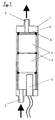
- the reactor shown in FIG. 1 has a housing 1 with an inlet opening 2 at the lower end with reference to FIG. 1.
- a heating device 3 for example, in the interior of the reactor housing 1.
- B. in the form of PTC heating elements, which without expensive control for heating the the inlet opening 2 in the reactor housing 1 flowing fuel to a certain temperature of z. B. 70 ° C.
- the heating device 3 could alternatively also be operated with a heating fluid heated in the engine or a heater.
- two reactor elements 4 are inserted in series in the reactor housing 1.
- a fine screen 5 which closes off the treatment chamber in the reactor housing 1 with reference to FIG. 1.
- the reactor elements 4 are sealed by means of circumferential seals 6 and 7 in the treatment chamber in relation to the reactor housing 1 in such a way that there is no flow gap on the circumference.
- the fuel is therefore forced to flow from the inlet opening 2 through the reactor elements 4 to an outlet opening 8 located at the upper end of the reactor housing 1 with reference to FIG. 1.
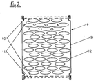
- FIG. 2 shows one of the reactor elements 4 of the device according to FIG. 1 on a larger scale. It consists of a can-shaped casing 9 and two screens 10, 11 each on the lower and upper front end with reference to FIG. 2.
- the two screens 10, 11 differ in their mesh size, which is coarse for the screen 11 and fine for the screen 10. You can e.g. B. in the sieve 11 0.5 - 3 mm and in the sieve 10 0.01 - 0.15 mm.
- the interior delimited by the casing 9 and the sieves 10, 11 is filled with granular reactor particles 12 which, in the example shown, have a pastille-like shape. They consist of an alloy with 80 - 99.8% tin and 0.2 - 20% copper.
- the grains or reactor particles 12 are in bulk in the casing 9. They are preferred after filling to remove oxides only in an organic acid, e.g. B. formic, acetic or oxalic acid, dipped and then in heating oil or gasoline. After this pretreatment, the reactor elements 4 can be stored and are ready for installation.
- organic acid e.g. B. formic, acetic or oxalic acid
- the reactor housing 1 has an inner diameter of 70 mm and a length of 200 mm.
- the inlet and outlet openings 2, 8 have a clear width of 10 mm.
- the heating device 3 with PTC heating elements reaches a maximum temperature of 120 ° C. and has a heating power of 140 W.
- the casing 9 of the reactor elements 4 consists of aluminum. Their outer diameter is 66 mm and their length is 45 mm.
- the flat reactor particles 12 consist of an alloy of 96% by weight of tin and 4% by weight of copper and have a diameter of 3 mm.
- the mesh size of the inner sieves 11 is 1 mm and that of the sieves 10 is 0.08 mm.
- the even finer sieve 5 in front of the outlet opening 8 has a mesh size of 0.04 mm.
- the reactor elements 4 were immersed in succession in acetic acid and then diesel oil. In the practical embodiment, three reactor elements 4 are provided in series one behind the other.
- the seals 6, 7 between the envelopes 9 and the reactor housing 1 are rubber sealing rings which have an outside diameter of 70 mm and an inside diameter of 65 mm.
- the grains or reactor particles 12 are only 0.5 mm in diameter. They have a copper core and are vapor-coated with tin on the surface. Since a tin-copper alloy has a lower melting point than copper and tin alone, it forms when tin is evaporated and the copper cores are at least superficially heated the desired alloy on the surface of the copper cores to a temperature slightly below the melting temperature of tin.
- the grains thus produced are suitable for sintering. In this way it is possible to produce porous blocks which can be inserted into a reactor housing 1 with or without a covering 9 by means of sealing rings 6, 7. Before installation, you can also rinse with an organic acid and then with petrol or diesel oil.
- the manufacturing process is somewhat more expensive overall than that of reactor elements 4 with a loose granular bed according to FIG. 2, but because of the smaller grains with smaller outer dimensions of the reactor element, the same effective surface is achieved as for the reactor elements 4 with loose granular bed. Therefore, when using sintered blocks as reactor elements, the tubular reactor housing 1 can have an inner diameter of, for. B. only 44 mm and a length of 150 mm. There are inlet and outlet openings 2, 8 with a clear width of 6 mm.
- the heating device 3 in turn contains PTC heating elements with a maximum temperature of 120 ° C., in which case the heating power is 45 W.
- the two reactor bodies consist of an aluminum shell with an outer diameter of 40 mm and a length of 35 mm with a filling which each consists of a sintered block which was obtained from tin and copper oxide particles of approximately 0.3 mm in diameter .
- the weight ratio of tin oxide to copper oxide was approximately 98 to 2.
- the material was sintered at 1100 ° C. and has a water absorption of approximately 30%.
- the sintering blocks were reduced superficially in a stream of hydrogen at 300 ° C. over 30 minutes.
- the reactor elements were then immersed in acetic acid and gasoline in succession before being installed in the reactor housing.
- the device shown in FIG. 3 contains a reactor consisting of three reactor elements 22 in a multi-part housing 20.
- the reactor elements 22 can each contain a loose bed of granular reactor material, consisting of a tin-copper alloy with the above-mentioned alloy proportions, within an envelope and between the end screens.
- the reactor elements 22 can also be sintered blocks which, for. B. consist of copper vaporized with tin and then sintered. These sintered blocks can either be inserted directly into the housing 20 or initially in envelopes, which are then inserted into the reactor housing 20.
- a catalyst 24 is arranged in the flow path of the rapeseed oil to be treated in series with the reactor elements 22 and in the flow direction in front of them.
- the catalyst 24 is a honeycomb catalyst made of LaCoO3-coated cordierite and serves to crack the long molecular chains of the rapeseed oil and to reduce its oxygen content. It is heated to a temperature of approximately 400 ° during operation by means of a heating device 26 attached to it.
- a heating device 28 with a multiplicity of PTC heating elements is also provided in the flow direction upstream of the catalytic converter 24, a heating device 28 with a multiplicity of PTC heating elements is also provided.
- the device shown in FIG. 3 has a first heat exchanger 30 between the catalyst 24 and the reactor elements 22 and a second heat exchanger 32 in the flow direction behind the reactor elements 22.
- the heat exchangers 30 and 32 are each connected to a steam separator 34 and 36, which is each connected to a steam line 38 leading to the air intake line of a burner (not shown).
- the rapeseed oil to be treated or another oil obtained from plants is introduced into the heat exchanger 32 via a feed line 40 and thus absorbs heat from the finished treated fuel oil flowing out of the reactor elements 22, which passes over after flowing through the heat exchanger 32 a line 42 flows to the burner, not shown.
- the rapeseed oil which has already been preheated in the heat exchanger 32 is fed via a line 44, on which the steam separator 36 is arranged, to the even hotter heat exchanger 30 between the catalyst 24 and the reactor elements 22.
- the line 46 leads the rapeseed oil or other crude oil into an antechamber 48 of the honeycomb catalytic converter 24, where the heating device 28 heats the crude oil previously preheated in the heat exchangers before it enters the catalytic converter 24.
- the crude oil in the catalyst 24 reaches a temperature of approximately 400 ° C.
- the long molecular chains of the crude oil are cracked and the oxygen content is reduced.
- the thus treated, still hot oil is then cooled in the heat exchanger 30, but still has a temperature of z. B. about 200 ° C.
- the reactor generates enough ignition seeds in the fuel oil so that when it comes after Flow through the heat exchanger 32 via the line 42 leaves the reactor housing 20, is suitable for sufficiently clean combustion or as a fuel.
Landscapes
- Engineering & Computer Science (AREA)
- Chemical & Material Sciences (AREA)
- Combustion & Propulsion (AREA)
- Mechanical Engineering (AREA)
- General Engineering & Computer Science (AREA)
- Chemical Kinetics & Catalysis (AREA)
- Catalysts (AREA)
- Production Of Liquid Hydrocarbon Mixture For Refining Petroleum (AREA)
- Physical Or Chemical Processes And Apparatus (AREA)
- Lubricants (AREA)
- Fats And Perfumes (AREA)
- Fertilizers (AREA)
- Exhaust Gas After Treatment (AREA)
Applications Claiming Priority (2)
| Application Number | Priority Date | Filing Date | Title |
|---|---|---|---|
| DE19619454A DE19619454A1 (de) | 1996-05-14 | 1996-05-14 | Reaktor zur Dotierung von Treibstoffen und Brennstoffen mit zinnhaltigen Materialien |
| DE19619454 | 1996-05-14 |
Publications (3)
| Publication Number | Publication Date |
|---|---|
| EP0807754A2 true EP0807754A2 (fr) | 1997-11-19 |
| EP0807754A3 EP0807754A3 (fr) | 1998-04-22 |
| EP0807754B1 EP0807754B1 (fr) | 2001-03-21 |
Family
ID=7794308
Family Applications (1)
| Application Number | Title | Priority Date | Filing Date |
|---|---|---|---|
| EP96117918A Expired - Lifetime EP0807754B1 (fr) | 1996-05-14 | 1996-11-08 | Dispositif de traitement de carburant dérivé d'huile minérale ou de plantes |
Country Status (7)
| Country | Link |
|---|---|
| US (1) | US5816225A (fr) |
| EP (1) | EP0807754B1 (fr) |
| AT (1) | ATE199965T1 (fr) |
| BR (1) | BR9700059A (fr) |
| DE (2) | DE19619454A1 (fr) |
| JO (1) | JO1962B1 (fr) |
| ZA (1) | ZA974128B (fr) |
Cited By (1)
| Publication number | Priority date | Publication date | Assignee | Title |
|---|---|---|---|---|
| CN110325727A (zh) * | 2017-03-02 | 2019-10-11 | 罗德里戈·柯基斯桑切斯孔查 | 用于优化催化合金的性能并改善其消除烃类燃料中的微生物污染物的性质的流体力学系统 |
Families Citing this family (55)
| Publication number | Priority date | Publication date | Assignee | Title |
|---|---|---|---|---|
| US7808479B1 (en) | 2003-09-02 | 2010-10-05 | Apple Inc. | Ambidextrous mouse |
| JP2003301749A (ja) * | 2002-04-08 | 2003-10-24 | Hitachi Ltd | 燃料気化促進装置 |
| DE10216462A1 (de) * | 2002-04-12 | 2003-10-23 | Wolfgang Hornig | Oberflächenreaktor |
| US7656393B2 (en) | 2005-03-04 | 2010-02-02 | Apple Inc. | Electronic device having display and surrounding touch sensitive bezel for user interface and control |
| US11275405B2 (en) | 2005-03-04 | 2022-03-15 | Apple Inc. | Multi-functional hand-held device |
| US7812827B2 (en) | 2007-01-03 | 2010-10-12 | Apple Inc. | Simultaneous sensing arrangement |
| US8493331B2 (en) | 2007-06-13 | 2013-07-23 | Apple Inc. | Touch detection using multiple simultaneous frequencies |
| US8673163B2 (en) | 2008-06-27 | 2014-03-18 | Apple Inc. | Method for fabricating thin sheets of glass |
| US7810355B2 (en) | 2008-06-30 | 2010-10-12 | Apple Inc. | Full perimeter chemical strengthening of substrates |
| US10031549B2 (en) | 2008-07-10 | 2018-07-24 | Apple Inc. | Transitioning between modes of input |
| US20100006350A1 (en) * | 2008-07-11 | 2010-01-14 | Elias John G | Stylus Adapted For Low Resolution Touch Sensor Panels |
| US8300019B2 (en) | 2008-07-15 | 2012-10-30 | Apple Inc. | Capacitive sensor coupling correction |
| US9335868B2 (en) * | 2008-07-31 | 2016-05-10 | Apple Inc. | Capacitive sensor behind black mask |
| US8743091B2 (en) * | 2008-07-31 | 2014-06-03 | Apple Inc. | Acoustic multi-touch sensor panel |
| US9606663B2 (en) * | 2008-09-10 | 2017-03-28 | Apple Inc. | Multiple stimulation phase determination |
| US9348451B2 (en) * | 2008-09-10 | 2016-05-24 | Apple Inc. | Channel scan architecture for multiple stimulus multi-touch sensor panels |
| US8237667B2 (en) | 2008-09-10 | 2012-08-07 | Apple Inc. | Phase compensation for multi-stimulus controller |
| US8659556B2 (en) * | 2008-09-10 | 2014-02-25 | Apple Inc. | Advanced receive channel architecture |
| US8592697B2 (en) | 2008-09-10 | 2013-11-26 | Apple Inc. | Single-chip multi-stimulus sensor controller |
| US9189048B2 (en) * | 2008-09-10 | 2015-11-17 | Apple Inc. | Circuit having a low power mode |
| US20100066683A1 (en) * | 2008-09-17 | 2010-03-18 | Shih-Chang Chang | Method for Transferring Thin Film to Substrate |
| US9063605B2 (en) | 2009-01-09 | 2015-06-23 | Apple Inc. | Thin glass processing using a carrier |
| US7918019B2 (en) * | 2009-01-09 | 2011-04-05 | Apple Inc. | Method for fabricating thin touch sensor panels |
| EP2404228B1 (fr) | 2009-03-02 | 2020-01-15 | Apple Inc. | Techniques de renforcement de protections en verre pour dispositifs électroniques portables |
| US8654524B2 (en) | 2009-08-17 | 2014-02-18 | Apple Inc. | Housing as an I/O device |
| US9778685B2 (en) | 2011-05-04 | 2017-10-03 | Apple Inc. | Housing for portable electronic device with reduced border region |
| US8104324B2 (en) | 2010-03-02 | 2012-01-31 | Bio-Applications, LLC | Intra-extra oral shock-sensing and indicating systems and other shock-sensing and indicating systems |
| US9213451B2 (en) | 2010-06-04 | 2015-12-15 | Apple Inc. | Thin glass for touch panel sensors and methods therefor |
| CA2805444C (fr) * | 2010-07-14 | 2015-11-10 | Scott Taucher | Procede et appareil de modification de carburant par ecoulement de liquide de refroidissement vers le catalyseur |
| US10189743B2 (en) | 2010-08-18 | 2019-01-29 | Apple Inc. | Enhanced strengthening of glass |
| US8824140B2 (en) | 2010-09-17 | 2014-09-02 | Apple Inc. | Glass enclosure |
| US8950215B2 (en) | 2010-10-06 | 2015-02-10 | Apple Inc. | Non-contact polishing techniques for reducing roughness on glass surfaces |
| US9725359B2 (en) | 2011-03-16 | 2017-08-08 | Apple Inc. | Electronic device having selectively strengthened glass |
| US10781135B2 (en) | 2011-03-16 | 2020-09-22 | Apple Inc. | Strengthening variable thickness glass |
| US9128666B2 (en) | 2011-05-04 | 2015-09-08 | Apple Inc. | Housing for portable electronic device with reduced border region |
| US9944554B2 (en) | 2011-09-15 | 2018-04-17 | Apple Inc. | Perforated mother sheet for partial edge chemical strengthening and method therefor |
| US9516149B2 (en) | 2011-09-29 | 2016-12-06 | Apple Inc. | Multi-layer transparent structures for electronic device housings |
| US10144669B2 (en) | 2011-11-21 | 2018-12-04 | Apple Inc. | Self-optimizing chemical strengthening bath for glass |
| US10133156B2 (en) | 2012-01-10 | 2018-11-20 | Apple Inc. | Fused opaque and clear glass for camera or display window |
| US8773848B2 (en) | 2012-01-25 | 2014-07-08 | Apple Inc. | Fused glass device housings |
| US9176604B2 (en) | 2012-07-27 | 2015-11-03 | Apple Inc. | Stylus device |
| US9946302B2 (en) | 2012-09-19 | 2018-04-17 | Apple Inc. | Exposed glass article with inner recessed area for portable electronic device housing |
| US9459661B2 (en) | 2013-06-19 | 2016-10-04 | Apple Inc. | Camouflaged openings in electronic device housings |
| US8988390B1 (en) | 2013-07-03 | 2015-03-24 | Apple Inc. | Frequency agile touch processing |
| US9886062B2 (en) | 2014-02-28 | 2018-02-06 | Apple Inc. | Exposed glass article with enhanced stiffness for portable electronic device housing |
| US11036318B2 (en) | 2015-09-30 | 2021-06-15 | Apple Inc. | Capacitive touch or proximity detection for crown |
| WO2018023080A2 (fr) | 2016-07-29 | 2018-02-01 | Apple Inc. | Méthodologie et application de détection tactile acoustique |
| US11157115B2 (en) | 2017-03-31 | 2021-10-26 | Apple Inc. | Composite cover material for sensitivity improvement of ultrasonic touch screens |
| US11347355B2 (en) | 2017-05-24 | 2022-05-31 | Apple Inc. | System and method for acoustic touch and force sensing |
| US11334196B2 (en) | 2017-05-24 | 2022-05-17 | Apple Inc. | System and method for acoustic touch and force sensing |
| US11144158B2 (en) | 2017-05-24 | 2021-10-12 | Apple Inc. | Differential acoustic touch and force sensing |
| US10949030B2 (en) | 2017-09-26 | 2021-03-16 | Apple Inc. | Shear-poled curved piezoelectric material |
| US10802651B2 (en) | 2018-01-30 | 2020-10-13 | Apple Inc. | Ultrasonic touch detection through display |
| US11366552B2 (en) | 2018-02-06 | 2022-06-21 | Apple, Inc. | Ultrasonic polarizer |
| US10725573B2 (en) | 2018-08-06 | 2020-07-28 | Apple Inc. | Annular piezoelectric structure for ultrasonic touch sensing |
Family Cites Families (11)
| Publication number | Priority date | Publication date | Assignee | Title |
|---|---|---|---|---|
| JPS58122984A (ja) * | 1982-01-19 | 1983-07-21 | Matsushita Electric Ind Co Ltd | 炭化水素燃料改質装置 |
| US4517926A (en) * | 1982-04-19 | 1985-05-21 | Optimizer, Limited | Device for improving fuel efficiency and method of use therefor |
| US4429665A (en) * | 1982-08-17 | 1984-02-07 | Brown Bill H | Fuel treating device and method |
| US4715325A (en) * | 1986-06-19 | 1987-12-29 | Walker Claud W | Pollution control through fuel treatment |
| US4876989A (en) * | 1988-05-10 | 1989-10-31 | Technology Development Associates, Inc. | Enhanced performance of alcohol fueled engine during cold conditions |
| DE9103500U1 (de) * | 1991-03-21 | 1991-07-25 | Sander, Anita, 7263 Bad Liebenzell | Vorrichtung zur Energieeinsparung und Abgasminderung bei Verbrennungsmotoren u.dgl. Verbrennungsanlagen |
| US5167782A (en) * | 1991-03-27 | 1992-12-01 | Marlow John R | Method and apparatus for treating fuel |
| US5092303A (en) * | 1991-04-18 | 1992-03-03 | Advanced Research Ventures, Inc. | In-line fuel preconditioner |
| DE4213808A1 (de) * | 1992-04-27 | 1993-10-28 | Christian Koch | Vorrichtung zur Dotierung von Treibstoffen mit metallischen Homogenkatalysatoren und Verfahren zu seiner Herstellung |
| US5305725A (en) * | 1992-09-11 | 1994-04-26 | Marlow John R | Method and apparatus for treating fuel |
| US5524594A (en) * | 1993-12-08 | 1996-06-11 | E.P.A. Ecology Pure Air, Inc. | Motor fuel performance enhancer |
-
1996
- 1996-05-14 DE DE19619454A patent/DE19619454A1/de not_active Withdrawn
- 1996-10-28 US US08/738,526 patent/US5816225A/en not_active Expired - Fee Related
- 1996-11-08 DE DE59606637T patent/DE59606637D1/de not_active Expired - Fee Related
- 1996-11-08 AT AT96117918T patent/ATE199965T1/de not_active IP Right Cessation
- 1996-11-08 EP EP96117918A patent/EP0807754B1/fr not_active Expired - Lifetime
-
1997
- 1997-01-14 BR BR9700059-0A patent/BR9700059A/pt unknown
- 1997-05-13 ZA ZA974128A patent/ZA974128B/xx unknown
- 1997-05-15 JO JO19971962A patent/JO1962B1/en active
Non-Patent Citations (1)
| Title |
|---|
| None |
Cited By (2)
| Publication number | Priority date | Publication date | Assignee | Title |
|---|---|---|---|---|
| CN110325727A (zh) * | 2017-03-02 | 2019-10-11 | 罗德里戈·柯基斯桑切斯孔查 | 用于优化催化合金的性能并改善其消除烃类燃料中的微生物污染物的性质的流体力学系统 |
| CN110325727B (zh) * | 2017-03-02 | 2022-04-05 | 罗德里戈·柯基斯桑切斯孔查 | 催化合金的流体力学系统 |
Also Published As
| Publication number | Publication date |
|---|---|
| EP0807754A3 (fr) | 1998-04-22 |
| ZA974128B (en) | 1998-11-16 |
| DE19619454A1 (de) | 1997-11-20 |
| JO1962B1 (en) | 1997-12-15 |
| EP0807754B1 (fr) | 2001-03-21 |
| DE59606637D1 (de) | 2001-04-26 |
| US5816225A (en) | 1998-10-06 |
| ATE199965T1 (de) | 2001-04-15 |
| BR9700059A (pt) | 1999-10-13 |
Similar Documents
| Publication | Publication Date | Title |
|---|---|---|
| EP0807754B1 (fr) | Dispositif de traitement de carburant dérivé d'huile minérale ou de plantes | |
| DE69216101T2 (de) | Partikelfilter zur reinigung von dieselmotorabgas | |
| DE69904132T2 (de) | Regenerationssystem für eine Abgasreinigungsanlage | |
| DE60126226T2 (de) | Katalysator zur Reinigung von Abgasen | |
| DE69906586T2 (de) | Filter für ein abgasrückführsystem der mittels eines ihn umhüllenden katalysators geheizt wird | |
| DE69026445T2 (de) | Abgasreinigungsvorrichtung für Brennkraftmaschinen | |
| DE3111228C2 (de) | Verfahren und Vorrichtung zum Beseitigen von Ruß aus den Abgasen einer Brennkraftmaschine | |
| DE3232729A1 (de) | Verfahren zur herabsetzung der zuendtemperatur von aus dem abgas von dieselmotoren herausgefiltertem dieselruss | |
| EP0892887A1 (fr) | Corps de filtre a trajets d'ecoulement resistant a la chaleur et pouvant etre regenere | |
| DE102018000383A1 (de) | Verschlossene Wabenstruktur | |
| DE19921974A1 (de) | Vorrichtung zum Reduzieren von schädlichen Bestandteilen im Abgas einer Brennkraftmaschine, insbesondere einer Diesel-Brennkraftmaschine | |
| DE3325292A1 (de) | Verfahren zur herstellung eines katalysators fuer die abgasreinigung | |
| DE19923478C2 (de) | Vorrichtung und Verfahren zur Abgasreinigung für Brennkraftmaschinen | |
| DE102005011657B4 (de) | Elektrisches Verdampferrohr für eine Abgasanlage einer Brennkraftmaschine und Abgasanlage einer Brennkraftmaschine mit einem derartigen Verdampferrohr | |
| DE1244477B (de) | Katalysator-Auspufftopf | |
| WO1997043539A1 (fr) | Dispositif pour traiter des carburants et des combustibles obtenus a partir d'huile minerale ou de plantes | |
| DE60210631T2 (de) | Verfahren zur Regenerierung einer Abgasfiltervorrichtung für Dieselmotoren und Vorrichtung dafür | |
| DE102012218475A1 (de) | Katalysator ohne PGM zum Verbrennen von Kohlenstoffruß sowie Filtrationsfilter und Vorrichtung zur Nachbearbeitung von Abgasen, welche diesen verwendet | |
| DE4303586A1 (en) | Exhaust emission controller for IC engine - has tubular filter elements with regenerative heaters embedded in thickened walls and mounted in tubular housing | |
| DE3112796A1 (de) | Aufgeladene brennkraftmaschine | |
| DE3517914C2 (fr) | ||
| DE19519137A1 (de) | Katalysatorzusammensetzung zum Reinigen von Diesel-Abgas, Katalysator unter Verwendung dieser Zusammensetzung und Herstellungsverfahren hierfür | |
| DE60314220T2 (de) | Verfahren zur Verminderung des Partikelgehaltes der Abgase eines Magerverbrennungsmotors oder dergleichen | |
| EP0427746B1 (fr) | Systeme de combine de prechauffage et de filtre, convenant en particulier pour un moteur de vehicule automobile | |
| DE2342472A1 (de) | Katalytischer kohlenmonoxidabscheider fuer abgas |
Legal Events
| Date | Code | Title | Description |
|---|---|---|---|
| PUAI | Public reference made under article 153(3) epc to a published international application that has entered the european phase |
Free format text: ORIGINAL CODE: 0009012 |
|
| AK | Designated contracting states |
Kind code of ref document: A2 Designated state(s): AT BE CH DE DK ES FI FR GB GR IE IT LI NL PT SE |
|
| PUAL | Search report despatched |
Free format text: ORIGINAL CODE: 0009013 |
|
| AK | Designated contracting states |
Kind code of ref document: A3 Designated state(s): AT BE CH DE DK ES FI FR GB GR IE IT LI NL PT SE |
|
| RHK1 | Main classification (correction) |
Ipc: F02M 27/02 |
|
| 17P | Request for examination filed |
Effective date: 19981022 |
|
| GRAG | Despatch of communication of intention to grant |
Free format text: ORIGINAL CODE: EPIDOS AGRA |
|
| 17Q | First examination report despatched |
Effective date: 20000222 |
|
| GRAG | Despatch of communication of intention to grant |
Free format text: ORIGINAL CODE: EPIDOS AGRA |
|
| GRAH | Despatch of communication of intention to grant a patent |
Free format text: ORIGINAL CODE: EPIDOS IGRA |
|
| GRAH | Despatch of communication of intention to grant a patent |
Free format text: ORIGINAL CODE: EPIDOS IGRA |
|
| RAP1 | Party data changed (applicant data changed or rights of an application transferred) |
Owner name: G.U.T. GOEMA GESELLSCHAFT FUER UMWELTTECHNIK GMBH |
|
| GRAA | (expected) grant |
Free format text: ORIGINAL CODE: 0009210 |
|
| AK | Designated contracting states |
Kind code of ref document: B1 Designated state(s): AT BE CH DE DK ES FI FR GB GR IE IT LI NL PT SE |
|
| PG25 | Lapsed in a contracting state [announced via postgrant information from national office to epo] |
Ref country code: NL Free format text: LAPSE BECAUSE OF FAILURE TO SUBMIT A TRANSLATION OF THE DESCRIPTION OR TO PAY THE FEE WITHIN THE PRESCRIBED TIME-LIMIT Effective date: 20010321 Ref country code: IE Free format text: LAPSE BECAUSE OF FAILURE TO SUBMIT A TRANSLATION OF THE DESCRIPTION OR TO PAY THE FEE WITHIN THE PRESCRIBED TIME-LIMIT Effective date: 20010321 Ref country code: FI Free format text: LAPSE BECAUSE OF FAILURE TO SUBMIT A TRANSLATION OF THE DESCRIPTION OR TO PAY THE FEE WITHIN THE PRESCRIBED TIME-LIMIT Effective date: 20010321 |
|
| REF | Corresponds to: |
Ref document number: 199965 Country of ref document: AT Date of ref document: 20010415 Kind code of ref document: T |
|
| REG | Reference to a national code |
Ref country code: CH Ref legal event code: EP |
|
| REG | Reference to a national code |
Ref country code: IE Ref legal event code: FG4D Free format text: GERMAN |
|
| REF | Corresponds to: |
Ref document number: 59606637 Country of ref document: DE Date of ref document: 20010426 |
|
| ITF | It: translation for a ep patent filed | ||
| GBT | Gb: translation of ep patent filed (gb section 77(6)(a)/1977) |
Effective date: 20010522 |
|
| PG25 | Lapsed in a contracting state [announced via postgrant information from national office to epo] |
Ref country code: SE Free format text: LAPSE BECAUSE OF FAILURE TO SUBMIT A TRANSLATION OF THE DESCRIPTION OR TO PAY THE FEE WITHIN THE PRESCRIBED TIME-LIMIT Effective date: 20010621 Ref country code: PT Free format text: LAPSE BECAUSE OF FAILURE TO SUBMIT A TRANSLATION OF THE DESCRIPTION OR TO PAY THE FEE WITHIN THE PRESCRIBED TIME-LIMIT Effective date: 20010621 Ref country code: DK Free format text: LAPSE BECAUSE OF FAILURE TO SUBMIT A TRANSLATION OF THE DESCRIPTION OR TO PAY THE FEE WITHIN THE PRESCRIBED TIME-LIMIT Effective date: 20010621 |
|
| PG25 | Lapsed in a contracting state [announced via postgrant information from national office to epo] |
Ref country code: GR Free format text: LAPSE BECAUSE OF FAILURE TO SUBMIT A TRANSLATION OF THE DESCRIPTION OR TO PAY THE FEE WITHIN THE PRESCRIBED TIME-LIMIT Effective date: 20010622 |
|
| ET | Fr: translation filed | ||
| NLV1 | Nl: lapsed or annulled due to failure to fulfill the requirements of art. 29p and 29m of the patents act | ||
| PG25 | Lapsed in a contracting state [announced via postgrant information from national office to epo] |
Ref country code: ES Free format text: LAPSE BECAUSE OF FAILURE TO SUBMIT A TRANSLATION OF THE DESCRIPTION OR TO PAY THE FEE WITHIN THE PRESCRIBED TIME-LIMIT Effective date: 20010927 |
|
| PG25 | Lapsed in a contracting state [announced via postgrant information from national office to epo] |
Ref country code: GB Free format text: LAPSE BECAUSE OF NON-PAYMENT OF DUE FEES Effective date: 20011108 Ref country code: AT Free format text: LAPSE BECAUSE OF NON-PAYMENT OF DUE FEES Effective date: 20011108 |
|
| REG | Reference to a national code |
Ref country code: IE Ref legal event code: FD4D |
|
| PG25 | Lapsed in a contracting state [announced via postgrant information from national office to epo] |
Ref country code: LI Free format text: LAPSE BECAUSE OF NON-PAYMENT OF DUE FEES Effective date: 20011130 Ref country code: CH Free format text: LAPSE BECAUSE OF NON-PAYMENT OF DUE FEES Effective date: 20011130 Ref country code: BE Free format text: LAPSE BECAUSE OF NON-PAYMENT OF DUE FEES Effective date: 20011130 |
|
| PGFP | Annual fee paid to national office [announced via postgrant information from national office to epo] |
Ref country code: FR Payment date: 20011204 Year of fee payment: 6 |
|
| REG | Reference to a national code |
Ref country code: GB Ref legal event code: IF02 |
|
| PLBE | No opposition filed within time limit |
Free format text: ORIGINAL CODE: 0009261 |
|
| STAA | Information on the status of an ep patent application or granted ep patent |
Free format text: STATUS: NO OPPOSITION FILED WITHIN TIME LIMIT |
|
| PGFP | Annual fee paid to national office [announced via postgrant information from national office to epo] |
Ref country code: DE Payment date: 20020128 Year of fee payment: 6 |
|
| 26N | No opposition filed | ||
| BERE | Be: lapsed |
Owner name: GOEMA G.- FUR UMWELTTECHNIK G.M.B.H. GUT Effective date: 20011130 |
|
| GBPC | Gb: european patent ceased through non-payment of renewal fee |
Effective date: 20011108 |
|
| REG | Reference to a national code |
Ref country code: CH Ref legal event code: PL |
|
| REG | Reference to a national code |
Ref country code: GB Ref legal event code: 7281 |
|
| PG25 | Lapsed in a contracting state [announced via postgrant information from national office to epo] |
Ref country code: DE Free format text: LAPSE BECAUSE OF NON-PAYMENT OF DUE FEES Effective date: 20030603 |
|
| PG25 | Lapsed in a contracting state [announced via postgrant information from national office to epo] |
Ref country code: FR Free format text: LAPSE BECAUSE OF NON-PAYMENT OF DUE FEES Effective date: 20030731 |
|
| REG | Reference to a national code |
Ref country code: FR Ref legal event code: ST |
|
| PG25 | Lapsed in a contracting state [announced via postgrant information from national office to epo] |
Ref country code: IT Free format text: LAPSE BECAUSE OF NON-PAYMENT OF DUE FEES;WARNING: LAPSES OF ITALIAN PATENTS WITH EFFECTIVE DATE BEFORE 2007 MAY HAVE OCCURRED AT ANY TIME BEFORE 2007. THE CORRECT EFFECTIVE DATE MAY BE DIFFERENT FROM THE ONE RECORDED. Effective date: 20051108 |