EP0807573B1 - Système pour la commande d'un volet compensateur de gouverne d'aéronef - Google Patents
Système pour la commande d'un volet compensateur de gouverne d'aéronef Download PDFInfo
- Publication number
- EP0807573B1 EP0807573B1 EP97400980A EP97400980A EP0807573B1 EP 0807573 B1 EP0807573 B1 EP 0807573B1 EP 97400980 A EP97400980 A EP 97400980A EP 97400980 A EP97400980 A EP 97400980A EP 0807573 B1 EP0807573 B1 EP 0807573B1
- Authority
- EP
- European Patent Office
- Prior art keywords
- aerodynamic surface
- value
- aircraft
- actuating member
- turned
- Prior art date
- Legal status (The legal status is an assumption and is not a legal conclusion. Google has not performed a legal analysis and makes no representation as to the accuracy of the status listed.)
- Expired - Lifetime
Links
- 230000007935 neutral effect Effects 0.000 claims description 8
- 238000005259 measurement Methods 0.000 claims description 5
- 230000007423 decrease Effects 0.000 claims description 2
- 230000006870 function Effects 0.000 description 12
- 238000010586 diagram Methods 0.000 description 6
- 235000021183 entrée Nutrition 0.000 description 6
- 241001080024 Telles Species 0.000 description 4
- 238000013519 translation Methods 0.000 description 4
- 239000003607 modifier Substances 0.000 description 3
- 230000002427 irreversible effect Effects 0.000 description 2
- 238000012360 testing method Methods 0.000 description 2
- 230000006978 adaptation Effects 0.000 description 1
- 238000012550 audit Methods 0.000 description 1
- 238000011161 development Methods 0.000 description 1
- 238000006073 displacement reaction Methods 0.000 description 1
- 238000012986 modification Methods 0.000 description 1
- 230000004048 modification Effects 0.000 description 1
- 238000005457 optimization Methods 0.000 description 1
- 210000000056 organ Anatomy 0.000 description 1
- 244000045947 parasite Species 0.000 description 1
- 230000003071 parasitic effect Effects 0.000 description 1
- 230000001681 protective effect Effects 0.000 description 1
- 230000035807 sensation Effects 0.000 description 1
Images



Classifications
-
- B—PERFORMING OPERATIONS; TRANSPORTING
- B64—AIRCRAFT; AVIATION; COSMONAUTICS
- B64C—AEROPLANES; HELICOPTERS
- B64C9/00—Adjustable control surfaces or members, e.g. rudders
- B64C9/10—Adjustable control surfaces or members, e.g. rudders one surface adjusted by movement of another, e.g. servo tabs
Definitions
- the present invention relates to a system for controlling a force compensation component for an aircraft control surface.
- the main object of the present invention is a system of trim tab control based on the principle of compensating flaps of the parallelogram type deformable, allowing to take into account many parameters which, until now, could not be integrated in said systems.
- the deflection of said compensating flap can be adjusted at any desired value depending on the deflection of said aerodynamic surface.
- Said control device can advantageously receive, in addition, at least one parameter from said aircraft and take take into account said parameter in the development of said order of ordered.
- Said actuating member, mobile and controllable can be a jack for example, this member being able to be positioned, either between said structure and said linkage for adjust the longitudinal position of an anchor point this one, either between two parts of said linkage for adjust the length of it.
- said parameters used in the device may be of a different nature, such as by example an aircraft speed, representative information the position of the high lift devices, a effort exerted by the pilot on the steering body, a load factor, an aircraft attitude angle, a aerodynamic angle of attack, representative information of an aircraft system configuration, the order effort refocusing (trim), etc ...
- said actuator has a neutral position for which said relationship between the steering angles of the compensating flap and the aerodynamic surface present a base value determined only by the geometry of said mechanical linkage, said parameter addressed to the control device is the air speed of the aircraft, and, under the action of said control device, said member takes an operational position which depends of said air speed and the steering angle of the aerodynamic surface and for which said relation takes an operational value different from said value of based.
- a system advantageously includes a sensor of the forces exerted by the pilot on said control member, and said parameter addressed to the control device is the measure of said forces delivered by said sensor, said actuating member taking, under the action of said control device, an operational position for which the deflection of said compensating flap with respect to said aerodynamic surface adjusts the steering of the latter to the corresponding value to said measurement of pilot efforts and function other parameters.
- Such other information may come, for example, from autopilot on board the aircraft, or be a safety signal, when said set value reaches a limit value not to be exceeded.
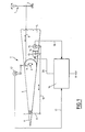
- Figure 1 is the block diagram of an exemplary embodiment of the control system according to the present invention.
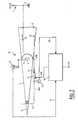
- FIG. 2 schematically illustrates a variant, at the level of the actuator, of the system of FIG. 1, with regard to concerns the connection between the compensating flap and the structure of the aircraft.
- Figure 3 shows the block diagram of an example of the actuator for the actuator of the systems of FIGS. 1 and 2.
- Figure 4 graphically illustrates an example of a relationship between the turning angles of the compensating flap and the aerodynamic surface.
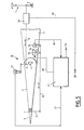
- Figure 5 is a block diagram of a variant of realization of the systems of FIGS. 1 and 2, with regard to relates to the actuator control device.
- Figure 6 shows the block diagram of an example of the control device for the system of Figure 5.
- Figure 7 graphically illustrates an example of operation produced by the control device of FIG. 6.
- Figure 8 is the block diagram of a variant of realization of the control device of figure 6.
- Figure 9 shows the block diagram of a variant of the Figure 5 system.
- Embodiment II of the compliant control system to the invention is very close of the exemplary embodiment I of FIG. 1.
- the second linkage 10 is made up of two parts 10A and 10B, which are connected to each other by the cylinder 13 (which in this case is advantageously linear), and whose ends opposite said cylinder 13 are respectively connected to the structure part 5 (at 21) and to the crankpin 11. So, in this case, the variation of the relation between the turning angles of the compensating flap 6 and of the aerodynamic surface 3 is obtained by varying the length of the second linkage 10, and no longer by translation thereof, as described with reference to the figure 1.
- the control device 16 can establish deflection laws of the compensating flap 6 as a function of the turning of the aerodynamic surface 3 and positioning said flap so as to give it a deflection which is functional flight conditions.
- Such shutter deflection laws compensator 6 can easily be established by calculation by knowing the geometry of the device and with the flight mechanics equations and then finally be put in point by flight and / or wind tunnel tests.
- the aircraft remains controllable with, however, a fixed relationship between the turning angles of flap 6 and the surface aerodynamics 3.
- the steering angle b takes the value K1.B + K2.F (B, p ).
- the parameter p can be of different nature.
- the operational value of the relationship between the turning angles of the compensating flap 6 and of the aerodynamic surface 3 can be either greater or smaller, when said high lift devices are removed than when they are retracted, depending on the type of aircraft.
- the system III of FIGS. 5 and 6 makes it possible to carry out a device in which the deflection of the surface aerodynamics 3 is a function, for example directly proportional, of the pilot's efforts.
- the error signal generated by subtractor 32 is used to add or entrench (in the servo device 33) to the steering angle B due to the geometry of the second linkage 10, the value required to meet the function sought.
- the compensating flap 6 is then used both to decrease and to increase aerodynamic forces, in order to control the position of the governs efforts on the steering body according to law desired.
- the movable member 14 of the actuating member 13 is positioned according to the difference between the position of setpoint Bc, which is a function of the forces exerted by the pilot on steering unit 1, and position B of the control surface, detected by sensor 12. This difference is exploited by the control device 27 to control the member 13 in a direction determined by the sign of the said deviation, up to cancellation of the error signal Bc-B.
- the movable member 14 of the actuating member 13 can be controlled by servo 33 at a speed proportional to the difference Bc-B until canceling it, with a possible limitation of the maximum speed.
- the servo 33 can include an integrator whose the input receives said deviation and the output of which represents the position order of the movable member 14.
- FIG 8 there is shown an alternative embodiment 38 of the control device 27.
- the device control 38 further includes a switch 39, interposed between table 31 and subtractor 32 and able to connect said subtractor 32, either the output from table 31, or a terminal 40.
- the steering signal can be applied the aerodynamic surface from an autopilot (not shown) boarded the aircraft. So when the switch 39 occupies the appropriate position, the system according to the present invention acts as a servomotor for autopilot.
- the aerodynamic surface 3 is a elevator
- on terminal 40 can be applied a prick signal, switch 39 on automatically from its position for which it connects the table 31 at subtractor 32 at its position for which it connects the latter to terminal 37, when the incidence of the aircraft exceeds a given threshold.
- the switch 39 can be activated by the signal from an incidence sensor.
- the linkage 8 can even be deleted.
- the linkage 8 has been eliminated and replaced by a device of artificial sensation 41, susceptible, only in with regard to the efforts to be exerted by the pilot, to exercise the same function.
Landscapes
- Engineering & Computer Science (AREA)
- Aviation & Aerospace Engineering (AREA)
- Control Of Position, Course, Altitude, Or Attitude Of Moving Bodies (AREA)
- Mechanical Control Devices (AREA)
- Transmission Devices (AREA)
- Aerodynamic Tests, Hydrodynamic Tests, Wind Tunnels, And Water Tanks (AREA)
Applications Claiming Priority (2)
| Application Number | Priority Date | Filing Date | Title |
|---|---|---|---|
| FR9606144A FR2748720B1 (fr) | 1996-05-17 | 1996-05-17 | Systeme pour la commande d'un volet compensateur de gouverne d'aeronef |
| FR9606144 | 1996-05-17 |
Publications (2)
| Publication Number | Publication Date |
|---|---|
| EP0807573A1 EP0807573A1 (fr) | 1997-11-19 |
| EP0807573B1 true EP0807573B1 (fr) | 2001-10-10 |
Family
ID=9492219
Family Applications (1)
| Application Number | Title | Priority Date | Filing Date |
|---|---|---|---|
| EP97400980A Expired - Lifetime EP0807573B1 (fr) | 1996-05-17 | 1997-04-30 | Système pour la commande d'un volet compensateur de gouverne d'aéronef |
Country Status (9)
| Country | Link |
|---|---|
| US (1) | US5913492A (id) |
| EP (1) | EP0807573B1 (id) |
| CN (1) | CN1080226C (id) |
| BR (1) | BR9702390A (id) |
| CA (1) | CA2204445C (id) |
| DE (1) | DE69707196T2 (id) |
| ES (1) | ES2165001T3 (id) |
| FR (1) | FR2748720B1 (id) |
| ID (1) | ID16899A (id) |
Families Citing this family (36)
| Publication number | Priority date | Publication date | Assignee | Title |
|---|---|---|---|---|
| SE508672C2 (sv) * | 1997-12-30 | 1998-10-26 | Saab Ab | Anordning och metod för styrkraftreglering vid ett mekaniskt styrsystem för ett flygplan |
| US6257528B1 (en) * | 1999-07-20 | 2001-07-10 | The Boeing Company | Vehicle control system and method employing control surface and geared tab |
| GB9918289D0 (en) | 1999-08-03 | 2000-05-24 | British Aerospace | Actuator system for aerospace controls and functions |
| AU2002312037A1 (en) * | 2001-05-24 | 2002-12-03 | Mcdonnell Helicopter Company Llc | The use of aerodynamic forces to assist in the control and positioning of aircraft control surfaces and variable geometry systems |
| US6672540B1 (en) | 2002-12-03 | 2004-01-06 | Rockwell Collins, Inc. | Actuator for aircraft stabilizers with a failure responsive lock control mechanism |
| US7182297B2 (en) * | 2003-01-17 | 2007-02-27 | The Insitu Group, Inc. | Method and apparatus for supporting aircraft components, including actuators |
| US6827311B2 (en) | 2003-04-07 | 2004-12-07 | Honeywell International, Inc. | Flight control actuation system |
| US7770842B2 (en) * | 2004-08-24 | 2010-08-10 | Honeywell International Inc. | Aircraft flight control surface actuation system communication architecture |
| US7549605B2 (en) * | 2005-06-27 | 2009-06-23 | Honeywell International Inc. | Electric flight control surface actuation system for aircraft flaps and slats |
| US20070007385A1 (en) * | 2005-06-27 | 2007-01-11 | Honeywell International, Inc. | Electric flight control surface actuation system electronic architecture |
| US8103393B2 (en) * | 2005-12-19 | 2012-01-24 | Vertical Power, Inc. | Aircraft exhaust gas temperature monitor |
| US20080237402A1 (en) * | 2005-12-19 | 2008-10-02 | Marc Ausman | Aircraft trim safety system and backup controls |
| US8340842B2 (en) | 2005-12-19 | 2012-12-25 | Vertical Power, Inc. | Aircraft emergency handling |
| US20070142980A1 (en) * | 2005-12-19 | 2007-06-21 | Marc Ausman | Avionics method and apparatus |
| US8346409B2 (en) | 2005-12-19 | 2013-01-01 | Vertical Power, Inc. | Variable speed flap retraction and notification |
| US7622818B2 (en) * | 2005-12-19 | 2009-11-24 | Vertical Power, Inc. | Backup electrical power system for solid-state aircraft power distribution systems |
| US7796054B2 (en) * | 2005-12-19 | 2010-09-14 | Vertical Power, Inc. | Aircraft electrical system evaluation |
| US7883059B2 (en) * | 2007-05-17 | 2011-02-08 | Insitu, Inc. | Actuator systems and associated methods for unmanned air vehicles and other applications |
| US8876063B2 (en) * | 2007-12-10 | 2014-11-04 | The Boeing Company | Flight control using multiple actuators on primary control surfaces with tabs |
| FR2927308B1 (fr) * | 2008-02-08 | 2010-10-22 | Airbus France | Systeme distribue de commande de vol. |
| US7973533B2 (en) | 2008-02-27 | 2011-07-05 | Vertical Power, Inc. | In-circuit testing for integrity of solid-state switches |
| DE102008022092A1 (de) * | 2008-05-05 | 2009-11-19 | Airbus Deutschland Gmbh | Fehlertolerantes Stellsystem zur Verstellung von Klappen eines Flugzeugs mit einer Verstell-Kinematik mit feststehender Drehachse |
| DE102008034444B4 (de) * | 2008-05-14 | 2013-09-05 | Diehl Aerospace Gmbh | Eingabesystem für eine Landeklappensteuerung eines Flugzeugs |
| US8235327B2 (en) * | 2009-03-18 | 2012-08-07 | Insitu, Inc. | Adjustable servomechanism assemblies and associated systems and methods |
| DE102009002435A1 (de) * | 2009-04-16 | 2010-10-21 | Airbus Deutschland Gmbh | Hochauftriebssystem für ein Flugzeug und Verfahren zum Detektieren von Fehlern in einem Hochauftriebssystem für ein Flugzeug |
| US10843796B2 (en) * | 2012-02-10 | 2020-11-24 | Merlin Technology, Inc. | Rotorcraft advanced autopilot control arrangement and methods |
| CN103043209B (zh) * | 2012-12-11 | 2016-04-20 | 江西洪都航空工业集团有限责任公司 | 一种农林飞机升降舵配平机构 |
| US9180961B2 (en) * | 2013-01-28 | 2015-11-10 | The Boeing Company | Control surface for creating variable camber along a wing |
| EP2805879B1 (en) * | 2013-05-22 | 2017-07-05 | Airbus Operations GmbH | Flap arrangement for a wing of an aircraft and an aircraft with a wing comprising such a flap arrangement |
| CN104648657A (zh) * | 2013-11-22 | 2015-05-27 | 中国航空工业集团公司西安飞机设计研究所 | 一种可抑制振动的带调整片操纵面 |
| CN103761899B (zh) * | 2013-12-31 | 2017-01-11 | 中国人民解放军空军航空大学军事仿真技术研究所 | 飞行模拟器可逆式操纵负荷系统力感仿真方法 |
| CN106184713B (zh) * | 2015-04-29 | 2018-07-24 | 陕西飞机工业(集团)有限公司 | 一种飞机升降舵调整片自动配平方法 |
| EP3448749B1 (en) * | 2016-04-25 | 2020-07-01 | Bombardier Inc. | Aircraft pitch control system with electronically geared elevator |
| CN109747813B (zh) * | 2017-11-07 | 2021-09-28 | 中国科学院沈阳自动化研究所 | 一种大载荷无人机尾翼驱动系统 |
| CN110450940B (zh) * | 2019-06-24 | 2022-09-20 | 陕西飞机工业(集团)有限公司 | 一种飞机的升降舵配平控制电路 |
| GB2622800B (en) * | 2022-09-27 | 2025-07-16 | Airbus Operations Ltd | Flight control surface |
Family Cites Families (13)
| Publication number | Priority date | Publication date | Assignee | Title |
|---|---|---|---|---|
| US2383779A (en) * | 1942-05-14 | 1945-08-28 | Bell Aircraft Corp | Aircraft control means |
| US2563757A (en) * | 1945-07-23 | 1951-08-07 | Lockheed Aircraft Corp | All-movable horizontal tail |
| US2568719A (en) * | 1947-04-09 | 1951-09-25 | Sperry Corp | Control system for aircraft control surface and tab |
| US2577439A (en) * | 1947-10-18 | 1951-12-04 | Curtiss Wright Corp | Differential spring balance tab |
| US2640665A (en) * | 1948-06-02 | 1953-06-02 | Cons Vultee Aircraft Corp | Aircraft trim tab control |
| FR1015687A (fr) * | 1949-03-04 | 1952-10-17 | A V Roe Canada Ltd | Dispositif de commande d'aéronefs en vol |
| US2557426A (en) * | 1950-01-13 | 1951-06-19 | Lockheed Aircraft Corp | Tab actuating mechanism |
| US2719684A (en) * | 1951-09-04 | 1955-10-04 | North American Aviation Inc | Aircraft control |
| US2817483A (en) * | 1951-10-17 | 1957-12-24 | Glenn L Martin Co | Aircraft control force modifier |
| US2721716A (en) * | 1952-03-31 | 1955-10-25 | Beadle John Charles William | Collapsible parachute |
| US3149272A (en) * | 1962-04-10 | 1964-09-15 | Sperry Rand Corp | Discriminating safety monitor for servo systems |
| US4595458A (en) * | 1985-05-17 | 1986-06-17 | Olin Corporation | Process for using selected fatty acid adducts of a 1,2,4-triazole as sizing or waterproofing agents for cellulosic materials |
| FR2600035B1 (fr) * | 1986-06-16 | 1988-10-21 | Aerospatiale | Systeme pour la commande d'une surface aerodynamique mobile d'un aeronef. |
-
1996
- 1996-05-17 FR FR9606144A patent/FR2748720B1/fr not_active Expired - Fee Related
-
1997
- 1997-04-30 DE DE69707196T patent/DE69707196T2/de not_active Expired - Lifetime
- 1997-04-30 EP EP97400980A patent/EP0807573B1/fr not_active Expired - Lifetime
- 1997-04-30 ES ES97400980T patent/ES2165001T3/es not_active Expired - Lifetime
- 1997-05-05 CA CA002204445A patent/CA2204445C/fr not_active Expired - Fee Related
- 1997-05-12 ID IDP971579A patent/ID16899A/id unknown
- 1997-05-13 US US08/855,190 patent/US5913492A/en not_active Expired - Fee Related
- 1997-05-17 CN CN97113518A patent/CN1080226C/zh not_active Expired - Fee Related
- 1997-05-19 BR BR9702390A patent/BR9702390A/pt not_active IP Right Cessation
Also Published As
| Publication number | Publication date |
|---|---|
| US5913492A (en) | 1999-06-22 |
| DE69707196D1 (de) | 2001-11-15 |
| FR2748720B1 (fr) | 1998-07-24 |
| FR2748720A1 (fr) | 1997-11-21 |
| CN1080226C (zh) | 2002-03-06 |
| BR9702390A (pt) | 1998-09-01 |
| CA2204445C (fr) | 2005-07-05 |
| ID16899A (id) | 1997-11-20 |
| DE69707196T2 (de) | 2002-05-29 |
| ES2165001T3 (es) | 2002-03-01 |
| EP0807573A1 (fr) | 1997-11-19 |
| CN1176208A (zh) | 1998-03-18 |
| CA2204445A1 (fr) | 1997-11-17 |
Similar Documents
| Publication | Publication Date | Title |
|---|---|---|
| EP0807573B1 (fr) | Système pour la commande d'un volet compensateur de gouverne d'aéronef | |
| EP0296951B1 (fr) | Système pour la commande d'un aéronef en roulis et en lacet | |
| EP1375342B1 (fr) | Avion à contrôle actif du vrillage de ses ailes | |
| EP0033053B1 (fr) | Avion à voilure fixe comportant des surfaces portantes placées en tandem | |
| EP0152714B1 (fr) | Système de commandes de vol pour aéronef | |
| EP2233396B1 (fr) | Procédé et dispositif pour optimiser le fonctionnement d'hélices propulsives disposées de part et d'autre du fuselage d'un giravion | |
| EP0435764A1 (fr) | Système pour diminuer les efforts appliqués à la voilure et notamment à l'emplanture des ailes d'un aéronef en vol | |
| EP0566452A1 (fr) | Hélicoptère monorotor à système anticouple mixte et procédé pour contrecarrer le couple induit par ce monorotor | |
| EP1223491B1 (fr) | Système pour commander automatiquement des dispositifs hypersustentateurs d'un aéronef durant le décollage | |
| EP2502825A1 (fr) | Pilotage de secours par vérin série pour chaine de commande de vol manuelle d'aéronef et Procédé | |
| EP1989104B1 (fr) | Systeme de commande electrique pour une gouverne de direction d'un avion | |
| EP1934662B1 (fr) | Procede et dispositif pour attenuer sur un aeronef les effets d'une turbulence verticale | |
| EP0454549B1 (fr) | Système pour le pilotage d'un avion en tangage | |
| EP1568605A1 (fr) | Procédé et dispositif pour l'optimisation du braquage des volets déporteurs d'un aéronef en vol | |
| EP0953504B1 (fr) | Aéronef à efforts de voilure diminués | |
| EP1026565A1 (fr) | Système pour la commande en lacet d'un aéronef | |
| FR2769284A1 (fr) | Dispositif de commande d'une surface aerodynamique de direction d'un helicoptere | |
| EP0680877B1 (fr) | Avion de transport à empennage avant | |
| FR2814433A1 (fr) | Dispositif de commande de vol d'un aeronef, en particulier d'un helicoptere | |
| FR2571021A1 (fr) | Dispositif pour la commande automatique d'un compensateur aerodynamique associe a une surface aerodynamique de commande d'un aeronef | |
| FR3042474A1 (fr) | Combinateur des commandes vol en lacet et de poussee pour un helicoptere hybride | |
| EP1858756B1 (fr) | Dispositif de compensation de jeu mecanique de commande de vol d'helicoptere | |
| WO2023156511A1 (fr) | Atterrisseur a longueur variable et aéronef équipé d'un tel atterrisseur | |
| FR3110545A1 (fr) | Procédé d’optimisation d’une consommation d’énergie d’un hélicoptère hybride en vol en palier |
Legal Events
| Date | Code | Title | Description |
|---|---|---|---|
| PUAI | Public reference made under article 153(3) epc to a published international application that has entered the european phase |
Free format text: ORIGINAL CODE: 0009012 |
|
| AK | Designated contracting states |
Kind code of ref document: A1 Designated state(s): DE ES GB NL SE |
|
| 17P | Request for examination filed |
Effective date: 19971208 |
|
| RAP1 | Party data changed (applicant data changed or rights of an application transferred) |
Owner name: AEROSPATIALE MATRA |
|
| GRAG | Despatch of communication of intention to grant |
Free format text: ORIGINAL CODE: EPIDOS AGRA |
|
| 17Q | First examination report despatched |
Effective date: 20001214 |
|
| GRAG | Despatch of communication of intention to grant |
Free format text: ORIGINAL CODE: EPIDOS AGRA |
|
| GRAH | Despatch of communication of intention to grant a patent |
Free format text: ORIGINAL CODE: EPIDOS IGRA |
|
| GRAH | Despatch of communication of intention to grant a patent |
Free format text: ORIGINAL CODE: EPIDOS IGRA |
|
| GRAA | (expected) grant |
Free format text: ORIGINAL CODE: 0009210 |
|
| AK | Designated contracting states |
Kind code of ref document: B1 Designated state(s): DE ES GB NL SE |
|
| GBT | Gb: translation of ep patent filed (gb section 77(6)(a)/1977) |
Effective date: 20011012 |
|
| REF | Corresponds to: |
Ref document number: 69707196 Country of ref document: DE Date of ref document: 20011115 |
|
| REG | Reference to a national code |
Ref country code: GB Ref legal event code: IF02 |
|
| REG | Reference to a national code |
Ref country code: ES Ref legal event code: FG2A Ref document number: 2165001 Country of ref document: ES Kind code of ref document: T3 |
|
| PLBE | No opposition filed within time limit |
Free format text: ORIGINAL CODE: 0009261 |
|
| STAA | Information on the status of an ep patent application or granted ep patent |
Free format text: STATUS: NO OPPOSITION FILED WITHIN TIME LIMIT |
|
| 26N | No opposition filed | ||
| PGFP | Annual fee paid to national office [announced via postgrant information from national office to epo] |
Ref country code: ES Payment date: 20100426 Year of fee payment: 14 |
|
| PGFP | Annual fee paid to national office [announced via postgrant information from national office to epo] |
Ref country code: NL Payment date: 20100413 Year of fee payment: 14 Ref country code: DE Payment date: 20100423 Year of fee payment: 14 |
|
| PGFP | Annual fee paid to national office [announced via postgrant information from national office to epo] |
Ref country code: SE Payment date: 20100415 Year of fee payment: 14 Ref country code: GB Payment date: 20100420 Year of fee payment: 14 |
|
| REG | Reference to a national code |
Ref country code: DE Ref legal event code: R119 Ref document number: 69707196 Country of ref document: DE |
|
| REG | Reference to a national code |
Ref country code: DE Ref legal event code: R119 Ref document number: 69707196 Country of ref document: DE |
|
| REG | Reference to a national code |
Ref country code: NL Ref legal event code: V1 Effective date: 20111101 |
|
| GBPC | Gb: european patent ceased through non-payment of renewal fee |
Effective date: 20110430 |
|
| REG | Reference to a national code |
Ref country code: SE Ref legal event code: EUG |
|
| PG25 | Lapsed in a contracting state [announced via postgrant information from national office to epo] |
Ref country code: NL Free format text: LAPSE BECAUSE OF NON-PAYMENT OF DUE FEES Effective date: 20111101 |
|
| PG25 | Lapsed in a contracting state [announced via postgrant information from national office to epo] |
Ref country code: GB Free format text: LAPSE BECAUSE OF NON-PAYMENT OF DUE FEES Effective date: 20110430 |
|
| REG | Reference to a national code |
Ref country code: ES Ref legal event code: FD2A Effective date: 20120524 |
|
| PG25 | Lapsed in a contracting state [announced via postgrant information from national office to epo] |
Ref country code: ES Free format text: LAPSE BECAUSE OF NON-PAYMENT OF DUE FEES Effective date: 20110501 |
|
| PG25 | Lapsed in a contracting state [announced via postgrant information from national office to epo] |
Ref country code: SE Free format text: LAPSE BECAUSE OF NON-PAYMENT OF DUE FEES Effective date: 20110501 |
|
| PG25 | Lapsed in a contracting state [announced via postgrant information from national office to epo] |
Ref country code: DE Free format text: LAPSE BECAUSE OF NON-PAYMENT OF DUE FEES Effective date: 20111031 |