EP0807553B1 - A control device for an acoustic indicator, particularly for the steering wheel of a motor vehicle - Google Patents
A control device for an acoustic indicator, particularly for the steering wheel of a motor vehicle Download PDFInfo
- Publication number
- EP0807553B1 EP0807553B1 EP97107953A EP97107953A EP0807553B1 EP 0807553 B1 EP0807553 B1 EP 0807553B1 EP 97107953 A EP97107953 A EP 97107953A EP 97107953 A EP97107953 A EP 97107953A EP 0807553 B1 EP0807553 B1 EP 0807553B1
- Authority
- EP
- European Patent Office
- Prior art keywords
- push
- acoustic indicator
- control device
- steering wheel
- button
- Prior art date
- Legal status (The legal status is an assumption and is not a legal conclusion. Google has not performed a legal analysis and makes no representation as to the accuracy of the status listed.)
- Expired - Lifetime
Links
- 230000003213 activating effect Effects 0.000 claims description 3
- 210000003813 thumb Anatomy 0.000 description 8
- 210000003811 finger Anatomy 0.000 description 7
- 210000004247 hand Anatomy 0.000 description 2
- 230000004913 activation Effects 0.000 description 1
- 230000000712 assembly Effects 0.000 description 1
- 238000000429 assembly Methods 0.000 description 1
- 238000004804 winding Methods 0.000 description 1
Images
Classifications
-
- B—PERFORMING OPERATIONS; TRANSPORTING
- B60—VEHICLES IN GENERAL
- B60Q—ARRANGEMENT OF SIGNALLING OR LIGHTING DEVICES, THE MOUNTING OR SUPPORTING THEREOF OR CIRCUITS THEREFOR, FOR VEHICLES IN GENERAL
- B60Q5/00—Arrangement or adaptation of acoustic signal devices
- B60Q5/001—Switches therefor
- B60Q5/003—Switches therefor mounted on the steering wheel
Definitions
- the present invention concerns a control device for an acoustic indicator, particularly for the steering wheel of a motor vehicle; more particularly it concerns an improved acoustic indicator control device, including at least a second additional push-button located on a rear face, with respect to the driver, of the spokes of the steering wheel, joined to the known front push-button, and in a better position to enable the quicker and easier operation of the acoustic indicator by utilising all of the fingers of the hands as well as the thumb.
- the object of the present invention is therefore to provide an acoustic indicator control device located on the spokes of the steering wheel of a motor vehicle, which is free from the disadvantages described above and which enables the push-button or push-buttons to be operated more quickly and easily without having to remove the thumb from the steering wheel, and with the possibility also of using the other fingers of the hand.
- a control device for an acoustic indicator particularly for the steering wheel of a motor vehicle, including means for actuating the said acoustic indicator, disposed on at least one spoke of the said steering wheel and operable by at least one of the driver's fingers, and electrical contact means disposed on the said spoke and actuated by the said actuation means to activate the said acoustic indicator, characterised in that the said actuation means include first and second push-buttons for activating the said acoustic indicator, located on opposite faces of the said at least one spoke, each of the said push-buttons being able to actuate the said contact means in order to activate the said acoustic indicator.
- the acoustic indicator control device is characterised in that the said first and second push-buttons are joined by a connection element passing through the thickness of the said spoke.
- a steering wheel 1 of a motor vehicle is constituted by a rim 2, a hub 3 and one or more spokes 4 joining the rim 2 to the hub 3; the hub 3 is mounted on a steering column 5 of the steering wheel about which the steering wheel 1 is turnable in both directions.
- the steering wheel 1 has two spokes 4a and 4b disposed in a conventional known position at approximately 180° with respect to each other or, more commonly, according to the hands of a clock in the "ten-to-two" position; in the rest position, that is, when driving in a straight line, the spokes are disposed such that they are aligned substantially horizontally.
- the device for controlling the acoustic indicator or horn 7 is located on the spokes 4, in the region 6 where the spokes 4 join the rim 2 of the steering wheel 1; for simplicity, only one of two possible horn control devices is represented in the drawings; in particular, in some sports car steering wheels, the zone 6 is partly sunken so as to form a depression to improve the grip of the driver's thumbs on the steering wheel.
- the control device includes two actuation means 8 constituted by a first push-button 9 disposed on a front face 10 of the spoke 4, facing the driver, in a position adjacent the junction 6 of the spoke 4 with the rim 2 of the steering wheel 1, and a second push-button 11 located on the opposite face 12 of the spoke 4 and attached to the first push-button by a connection element 14, constituted by a substantially rigid bar 14 joined to both push-buttons 9, 11, and which passes through the thickness of the spoke 4.
- control device can be operated in two ways because the first push-button 9 can be operated by the driver's thumb and the second, opposite, push-button 11 can be operated by the other fingers when the steering wheel is turned to a position in which the thumb is unable easily to operate the first, front push-button 9.
- the control device further includes electrical contact means 15 disposed on the spoke 4 and actuated by one or other of the two push-buttons 9 and 11; the contact means 15 are constituted by a switch of known type, for example, of capacitive type, in which two movable electrically conductive elements respectively close an activation circuit, not shown, of the horn 7 when they are brought together.
- the two electrically conductive elements are respectively constituted by a pair of conductive elements 16a and 16b, mounted opposite each other and spaced apart on the bar 14, and movable with respect to a fixed conductive element 17 mounted between the elements 16 on the spoke 4.
- the conductive elements 16 are carried on a support 18 of the bar 14 formed between a tab 19 and one of the push-buttons 9 or 11, for example, the push-button 9 in Figure 2.
- the push-buttons 9 and 11 are held in an intermediate position in which the conductive elements 16a and 16b are equidistant from the fixed conductive element 17 by a resilient biasing member such as, for example, a double acting leaf spring which, for simplicity, is not shown in the drawings.
- a resilient biasing member such as, for example, a double acting leaf spring which, for simplicity, is not shown in the drawings.
- the push-buttons 9 and 11 may be separated from each other and each of them associated with a conductive element 16a or 16b so as separately to activate the horn 7, it still being the case that the rear push-button 11 is operated by the other fingers of the hand which grip the back of the steering wheel with respect to the driver.
- the rear push-button 11 projects (it is shaped) slightly from the face 12 of the spoke 4 to facilitate the location of the same push-button by the fingers which grip the back of the steering wheel 1 with respect to the driver, especially when steering.
- the spokes 4 and the rim 2 may be covered with a cover 20 of aesthetically appropriate material, which also covers the push-buttons 9 and 11.
Landscapes
- Physics & Mathematics (AREA)
- Acoustics & Sound (AREA)
- Engineering & Computer Science (AREA)
- Mechanical Engineering (AREA)
- Steering Controls (AREA)
- Emergency Alarm Devices (AREA)
Description
- The present invention concerns a control device for an acoustic indicator, particularly for the steering wheel of a motor vehicle; more particularly it concerns an improved acoustic indicator control device, including at least a second additional push-button located on a rear face, with respect to the driver, of the spokes of the steering wheel, joined to the known front push-button, and in a better position to enable the quicker and easier operation of the acoustic indicator by utilising all of the fingers of the hands as well as the thumb.
- In known acoustic indicator control assemblies located on the steering wheel of the motor vehicle, the hub of which is not available due to the presence of, for example, a so-called "air bag", the push-buttons for operating the acoustic indicator are located on the spokes where they join the rim of the steering wheel, on the side facing the driver. Such a push-button is known from US-A-4 590 340.
- In this position, the push-buttons are only readily operable by the driver's thumbs when the steering wheel is gripped in the region adjacent the push-buttons, that is, at the junction between the spokes and the rim of the steering wheel; this situation only arises when the car is travelling in a straight line and the steering wheel remains in the straight ahead position; when travelling on winding routes when the steering wheel is continually turned and the rim is therefore gripped mainly away from the junction with the spokes, it becomes difficult, at times impossible, to operate the push-buttons with the thumb without removing a hand from the steering wheel, to the detriment of driving safety.
- The object of the present invention is therefore to provide an acoustic indicator control device located on the spokes of the steering wheel of a motor vehicle, which is free from the disadvantages described above and which enables the push-button or push-buttons to be operated more quickly and easily without having to remove the thumb from the steering wheel, and with the possibility also of using the other fingers of the hand.
- In accordance with the stated object, there is provided a control device for an acoustic indicator, particularly for the steering wheel of a motor vehicle, including means for actuating the said acoustic indicator, disposed on at least one spoke of the said steering wheel and operable by at least one of the driver's fingers, and electrical contact means disposed on the said spoke and actuated by the said actuation means to activate the said acoustic indicator, characterised in that the said actuation means include first and second push-buttons for activating the said acoustic indicator, located on opposite faces of the said at least one spoke, each of the said push-buttons being able to actuate the said contact means in order to activate the said acoustic indicator.
- According to a further aspect of the invention, the acoustic indicator control device is characterised in that the said first and second push-buttons are joined by a connection element passing through the thickness of the said spoke.
- A detailed description of a preferred embodiment of the acoustic indicator control device according to the invention, will now be given by way of non-limitative example, with reference to the accompanying drawings, in which:
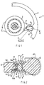
- Figure 1 is a front view in partial section, from the side opposite the driver, of a portion of a motor vehicle steering wheel carrying an acoustic indicator control device according to the present invention; and
- Figure 2 is a partial section on an enlarged scale of the steering wheel of Figure 1, taken on the line II-II.
-
- With reference to Figures 1 and 2, a
steering wheel 1 of a motor vehicle is constituted by arim 2, a hub 3 and one or more spokes 4 joining therim 2 to the hub 3; the hub 3 is mounted on a steering column 5 of the steering wheel about which thesteering wheel 1 is turnable in both directions. - According to a preferred, non-limitative embodiment, the
steering wheel 1 has two spokes 4a and 4b disposed in a conventional known position at approximately 180° with respect to each other or, more commonly, according to the hands of a clock in the "ten-to-two" position; in the rest position, that is, when driving in a straight line, the spokes are disposed such that they are aligned substantially horizontally. - Since, in current models of motor vehicles, the interior of the hub 3 is reserved for housing emergency devices for the driver's safety in case of an accident, such as the so-called "air bag", the device for controlling the acoustic indicator or horn 7 is located on the spokes 4, in the
region 6 where the spokes 4 join therim 2 of thesteering wheel 1; for simplicity, only one of two possible horn control devices is represented in the drawings; in particular, in some sports car steering wheels, thezone 6 is partly sunken so as to form a depression to improve the grip of the driver's thumbs on the steering wheel. - To overcome the disadvantage that the currently known control devices do not always enable the rapid and timely operation of the horn 7, the control device according to the invention includes two actuation means 8 constituted by a first push-
button 9 disposed on afront face 10 of the spoke 4, facing the driver, in a position adjacent thejunction 6 of the spoke 4 with therim 2 of thesteering wheel 1, and a second push-button 11 located on the opposite face 12 of the spoke 4 and attached to the first push-button by a connection element 14, constituted by a substantially rigid bar 14 joined to both push-buttons 9, 11, and which passes through the thickness of the spoke 4. - In this way the control device can be operated in two ways because the first push-
button 9 can be operated by the driver's thumb and the second, opposite, push-button 11 can be operated by the other fingers when the steering wheel is turned to a position in which the thumb is unable easily to operate the first, front push-button 9. - The control device further includes electrical contact means 15 disposed on the spoke 4 and actuated by one or other of the two push-
buttons 9 and 11; the contact means 15 are constituted by a switch of known type, for example, of capacitive type, in which two movable electrically conductive elements respectively close an activation circuit, not shown, of the horn 7 when they are brought together. In a preferred non-limitative embodiment, the two electrically conductive elements are respectively constituted by a pair of conductive elements 16a and 16b, mounted opposite each other and spaced apart on the bar 14, and movable with respect to a fixed conductive element 17 mounted between the elements 16 on the spoke 4. - The conductive elements 16 are carried on a
support 18 of the bar 14 formed between a tab 19 and one of the push-buttons 9 or 11, for example, the push-button 9 in Figure 2. - Therefore, by pressing either of the push-
buttons 9 or 11 respectively with the thumb in the direction indicated by an arrow "A", or with the other fingers in the direction of the arrow "P", the conductive elements 16 and 17 in both cases close an electrical circuit which activates the horn 7. - The push-
buttons 9 and 11 are held in an intermediate position in which the conductive elements 16a and 16b are equidistant from the fixed conductive element 17 by a resilient biasing member such as, for example, a double acting leaf spring which, for simplicity, is not shown in the drawings. - According to a different embodiment of the control device according to the present invention, the push-
buttons 9 and 11 may be separated from each other and each of them associated with a conductive element 16a or 16b so as separately to activate the horn 7, it still being the case that the rear push-button 11 is operated by the other fingers of the hand which grip the back of the steering wheel with respect to the driver. - The rear push-button 11 projects (it is shaped) slightly from the face 12 of the spoke 4 to facilitate the location of the same push-button by the fingers which grip the back of the
steering wheel 1 with respect to the driver, especially when steering. - To improve the aesthetic appearance of the
steering wheel 1 having the double actuation control device according to the invention, the spokes 4 and therim 2 may be covered with acover 20 of aesthetically appropriate material, which also covers the push-buttons 9 and 11.
Claims (6)
- A control device for an acoustic indicator (7) for the steering wheel (1) of a motor vehicle, including means (8) for actuating the said acoustic indicator (7) disposed on at least one spoke (4) of the said steering wheel (1), and operable by at least one of the driver's fingers, and electrical contact means (15) disposed on the said spoke (4) and actuated by the said actuation means (8) to activate the said acoustic indicator (7), characterised in that the said actuation means (8) include a first push-button (9) and a second push-button (11) for activating the said acoustic indicator (7), disposed on opposite faces (10; 12) of the said at least one spoke (4), each of the said push-buttons (9; 11) being able to actuate the said contact means (15) for activating the said acoustic indicator (7).
- A control device for an acoustic indicator (7) according to Claim 1, characterised in that the said push-buttons (9; 11) are connected by a connection element (14) which extends through the thickness of the said spoke (4).
- A control device for an acoustic indicator (7) according to Claim 2, characterised in that the said connection element is constituted by a substantially rigid bar (14) provided with means (18; 19) for actuating the said electrical contact means (15).
- A control device for an acoustic indicator according to any preceding claim, characterised in that the said contact means (15) include an electrical switch constituted by a pair of conductive elements (16a; 16b) mounted facing and spaced apart on the said connection element (14), and movable with respect to a fixed conductive element (17) mounted on the spoke (4) in an intermediate position between the conductive elements (16a; 16b).
- A control device for an acoustic indicator according to any preceding claim, characterised in that the said second push-button (11) actuates the said electrical contact means (15) independently of the said first push-button.
- A control device for an acoustic indicator according to any preceding claim, characterised in that the said second push-button (11) projects from a rear face (12) of the said spoke (4) to facilitate the location of the said push-button (11) by the driver's fingers which grip the back of the said steering wheel (1) with respect to the driver.
Applications Claiming Priority (2)
| Application Number | Priority Date | Filing Date | Title |
|---|---|---|---|
| ITTO960414 | 1996-05-17 | ||
| IT96TO000414A IT1285333B1 (en) | 1996-05-17 | 1996-05-17 | CONTROL DEVICE OF A HORN, PARTICULARLY FOR THE STEERING WHEEL OF A MOTOR VEHICLE. |
Publications (3)
| Publication Number | Publication Date |
|---|---|
| EP0807553A2 EP0807553A2 (en) | 1997-11-19 |
| EP0807553A3 EP0807553A3 (en) | 1998-05-20 |
| EP0807553B1 true EP0807553B1 (en) | 2001-10-31 |
Family
ID=11414641
Family Applications (1)
| Application Number | Title | Priority Date | Filing Date |
|---|---|---|---|
| EP97107953A Expired - Lifetime EP0807553B1 (en) | 1996-05-17 | 1997-05-15 | A control device for an acoustic indicator, particularly for the steering wheel of a motor vehicle |
Country Status (4)
| Country | Link |
|---|---|
| EP (1) | EP0807553B1 (en) |
| DE (1) | DE69707749T2 (en) |
| ES (1) | ES2163684T3 (en) |
| IT (1) | IT1285333B1 (en) |
Families Citing this family (4)
| Publication number | Priority date | Publication date | Assignee | Title |
|---|---|---|---|---|
| JP2001014986A (en) * | 1999-07-01 | 2001-01-19 | Alps Electric Co Ltd | Switch gear for steering wheel |
| JP3789284B2 (en) * | 2000-04-28 | 2006-06-21 | アルプス電気株式会社 | Switch unit for vehicle steering wheel |
| DE102011111123A1 (en) * | 2011-08-20 | 2013-02-21 | GM Global Technology Operations LLC (n. d. Gesetzen des Staates Delaware) | Device for controlling functions of electronic devices of a vehicle and vehicle with the device |
| DE102012020004A1 (en) * | 2012-10-12 | 2014-04-17 | Volkswagen Aktiengesellschaft | Control element mounted in interior of steering wheel of motor car, has components which are slidably supported and configured such that control element is pressed from left side of primary component in direction of primary component |
Family Cites Families (3)
| Publication number | Priority date | Publication date | Assignee | Title |
|---|---|---|---|---|
| DE7805602U1 (en) * | 1978-02-24 | 1978-06-08 | Zehender, Lothar, Ing.(Grad.), 7333 Ebersbach | Motor vehicle safety steering wheel |
| US4590340A (en) * | 1985-01-29 | 1986-05-20 | Nihon Plast Co., Ltd. | Steering wheel assembly for vehicles |
| DE4436291C1 (en) * | 1994-10-11 | 1995-09-28 | Opel Adam Ag | Automobile steering wheel with incorporated switch contacts |
-
1996
- 1996-05-17 IT IT96TO000414A patent/IT1285333B1/en active IP Right Grant
-
1997
- 1997-05-15 ES ES97107953T patent/ES2163684T3/en not_active Expired - Lifetime
- 1997-05-15 DE DE69707749T patent/DE69707749T2/en not_active Expired - Fee Related
- 1997-05-15 EP EP97107953A patent/EP0807553B1/en not_active Expired - Lifetime
Also Published As
| Publication number | Publication date |
|---|---|
| EP0807553A2 (en) | 1997-11-19 |
| ITTO960414A0 (en) | 1996-05-17 |
| ITTO960414A1 (en) | 1997-11-17 |
| EP0807553A3 (en) | 1998-05-20 |
| ES2163684T3 (en) | 2002-02-01 |
| IT1285333B1 (en) | 1998-06-03 |
| DE69707749D1 (en) | 2001-12-06 |
| DE69707749T2 (en) | 2002-08-08 |
Similar Documents
| Publication | Publication Date | Title |
|---|---|---|
| AU695452B2 (en) | Thermoplastic air bag cover having a unitary multifunctional domed switching module | |
| US6144297A (en) | Automobile steering wheel and turn signal buttons with turning indicia and/or indicators thereon | |
| EP0807553B1 (en) | A control device for an acoustic indicator, particularly for the steering wheel of a motor vehicle | |
| US5219415A (en) | Horn ring for a steering wheel having a restraint and method | |
| US20100326229A1 (en) | Steering wheel switch module | |
| US7038586B2 (en) | Vehicle horn actuation mechanism and method | |
| EP0702634B1 (en) | Compact control unit for motor vehicles, particularly trucks | |
| US20060044129A1 (en) | Facilitating signaling in a vehicle | |
| US5955944A (en) | Automobile steering wheel and turn and turn signal buttons with turning indicia and/or indicators thereon | |
| US20050046279A1 (en) | Steering wheel high beam switch | |
| US5331125A (en) | Steering wheel horn switch assembly including horn ring operator | |
| KR101793080B1 (en) | Vehicle driving operation device | |
| JPH0523362U (en) | Handle switch | |
| JPS6076443A (en) | Switch built-in steering wheel | |
| US1704710A (en) | Direction indicator for automobiles | |
| JP3539817B2 (en) | Handle unit | |
| JP7397021B2 (en) | switch unit | |
| JPS62194938A (en) | Switch device for turn signal indicator | |
| KR0122577Y1 (en) | Wiper Switch for Car Steering Wheel | |
| JP2012187953A (en) | Handle for small electric vehicle | |
| JP2003261083A (en) | Electric vehicle steering device | |
| GB2274149A (en) | Motor vehicle control devices for use by disabled drivers. | |
| KR100580037B1 (en) | Auxiliary handle of car steering wheel | |
| JP2023072506A (en) | handle | |
| JP2574693Y2 (en) | Membrane switch |
Legal Events
| Date | Code | Title | Description |
|---|---|---|---|
| PUAI | Public reference made under article 153(3) epc to a published international application that has entered the european phase |
Free format text: ORIGINAL CODE: 0009012 |
|
| AK | Designated contracting states |
Kind code of ref document: A2 Designated state(s): DE ES FR GB SE |
|
| PUAL | Search report despatched |
Free format text: ORIGINAL CODE: 0009013 |
|
| AK | Designated contracting states |
Kind code of ref document: A3 Designated state(s): DE ES FR GB SE |
|
| 17P | Request for examination filed |
Effective date: 19980918 |
|
| GRAG | Despatch of communication of intention to grant |
Free format text: ORIGINAL CODE: EPIDOS AGRA |
|
| 17Q | First examination report despatched |
Effective date: 20010220 |
|
| GRAG | Despatch of communication of intention to grant |
Free format text: ORIGINAL CODE: EPIDOS AGRA |
|
| GRAH | Despatch of communication of intention to grant a patent |
Free format text: ORIGINAL CODE: EPIDOS IGRA |
|
| GRAH | Despatch of communication of intention to grant a patent |
Free format text: ORIGINAL CODE: EPIDOS IGRA |
|
| GRAA | (expected) grant |
Free format text: ORIGINAL CODE: 0009210 |
|
| AK | Designated contracting states |
Kind code of ref document: B1 Designated state(s): DE ES FR GB SE |
|
| REF | Corresponds to: |
Ref document number: 69707749 Country of ref document: DE Date of ref document: 20011206 |
|
| REG | Reference to a national code |
Ref country code: GB Ref legal event code: IF02 |
|
| REG | Reference to a national code |
Ref country code: ES Ref legal event code: FG2A Ref document number: 2163684 Country of ref document: ES Kind code of ref document: T3 |
|
| ET | Fr: translation filed | ||
| PLBE | No opposition filed within time limit |
Free format text: ORIGINAL CODE: 0009261 |
|
| STAA | Information on the status of an ep patent application or granted ep patent |
Free format text: STATUS: NO OPPOSITION FILED WITHIN TIME LIMIT |
|
| 26N | No opposition filed | ||
| PGFP | Annual fee paid to national office [announced via postgrant information from national office to epo] |
Ref country code: FR Payment date: 20050530 Year of fee payment: 9 |
|
| PGFP | Annual fee paid to national office [announced via postgrant information from national office to epo] |
Ref country code: SE Payment date: 20050531 Year of fee payment: 9 Ref country code: ES Payment date: 20050531 Year of fee payment: 9 |
|
| PGFP | Annual fee paid to national office [announced via postgrant information from national office to epo] |
Ref country code: GB Payment date: 20050608 Year of fee payment: 9 |
|
| PGFP | Annual fee paid to national office [announced via postgrant information from national office to epo] |
Ref country code: DE Payment date: 20050726 Year of fee payment: 9 |
|
| PG25 | Lapsed in a contracting state [announced via postgrant information from national office to epo] |
Ref country code: GB Free format text: LAPSE BECAUSE OF NON-PAYMENT OF DUE FEES Effective date: 20060515 |
|
| PG25 | Lapsed in a contracting state [announced via postgrant information from national office to epo] |
Ref country code: SE Free format text: LAPSE BECAUSE OF NON-PAYMENT OF DUE FEES Effective date: 20060516 Ref country code: ES Free format text: LAPSE BECAUSE OF NON-PAYMENT OF DUE FEES Effective date: 20060516 |
|
| PG25 | Lapsed in a contracting state [announced via postgrant information from national office to epo] |
Ref country code: DE Free format text: LAPSE BECAUSE OF NON-PAYMENT OF DUE FEES Effective date: 20061201 |
|
| EUG | Se: european patent has lapsed | ||
| GBPC | Gb: european patent ceased through non-payment of renewal fee |
Effective date: 20060515 |
|
| REG | Reference to a national code |
Ref country code: FR Ref legal event code: ST Effective date: 20070131 |
|
| REG | Reference to a national code |
Ref country code: ES Ref legal event code: FD2A Effective date: 20060516 |
|
| PG25 | Lapsed in a contracting state [announced via postgrant information from national office to epo] |
Ref country code: FR Free format text: LAPSE BECAUSE OF NON-PAYMENT OF DUE FEES Effective date: 20060531 |