EP0807529B1 - A carriage assembly retaining two inkjet print cartridges - Google Patents
A carriage assembly retaining two inkjet print cartridges Download PDFInfo
- Publication number
- EP0807529B1 EP0807529B1 EP97113771A EP97113771A EP0807529B1 EP 0807529 B1 EP0807529 B1 EP 0807529B1 EP 97113771 A EP97113771 A EP 97113771A EP 97113771 A EP97113771 A EP 97113771A EP 0807529 B1 EP0807529 B1 EP 0807529B1
- Authority
- EP
- European Patent Office
- Prior art keywords
- unitary
- interconnect
- inkjet
- contacts
- electrical
- Prior art date
- Legal status (The legal status is an assumption and is not a legal conclusion. Google has not performed a legal analysis and makes no representation as to the accuracy of the status listed.)
- Expired - Lifetime
Links
Images


Classifications
-
- B—PERFORMING OPERATIONS; TRANSPORTING
- B41—PRINTING; LINING MACHINES; TYPEWRITERS; STAMPS
- B41J—TYPEWRITERS; SELECTIVE PRINTING MECHANISMS, i.e. MECHANISMS PRINTING OTHERWISE THAN FROM A FORME; CORRECTION OF TYPOGRAPHICAL ERRORS
- B41J2/00—Typewriters or selective printing mechanisms characterised by the printing or marking process for which they are designed
- B41J2/005—Typewriters or selective printing mechanisms characterised by the printing or marking process for which they are designed characterised by bringing liquid or particles selectively into contact with a printing material
- B41J2/01—Ink jet
- B41J2/17—Ink jet characterised by ink handling
- B41J2/175—Ink supply systems ; Circuit parts therefor
- B41J2/17503—Ink cartridges
- B41J2/17526—Electrical contacts to the cartridge
-
- B—PERFORMING OPERATIONS; TRANSPORTING
- B41—PRINTING; LINING MACHINES; TYPEWRITERS; STAMPS
- B41J—TYPEWRITERS; SELECTIVE PRINTING MECHANISMS, i.e. MECHANISMS PRINTING OTHERWISE THAN FROM A FORME; CORRECTION OF TYPOGRAPHICAL ERRORS
- B41J2/00—Typewriters or selective printing mechanisms characterised by the printing or marking process for which they are designed
- B41J2/005—Typewriters or selective printing mechanisms characterised by the printing or marking process for which they are designed characterised by bringing liquid or particles selectively into contact with a printing material
- B41J2/01—Ink jet
- B41J2/17—Ink jet characterised by ink handling
- B41J2/175—Ink supply systems ; Circuit parts therefor
- B41J2/17503—Ink cartridges
- B41J2/1752—Mounting within the printer
-
- B—PERFORMING OPERATIONS; TRANSPORTING
- B41—PRINTING; LINING MACHINES; TYPEWRITERS; STAMPS
- B41J—TYPEWRITERS; SELECTIVE PRINTING MECHANISMS, i.e. MECHANISMS PRINTING OTHERWISE THAN FROM A FORME; CORRECTION OF TYPOGRAPHICAL ERRORS
- B41J25/00—Actions or mechanisms not otherwise provided for
- B41J25/34—Bodily-changeable print heads or carriages
-
- B—PERFORMING OPERATIONS; TRANSPORTING
- B41—PRINTING; LINING MACHINES; TYPEWRITERS; STAMPS
- B41J—TYPEWRITERS; SELECTIVE PRINTING MECHANISMS, i.e. MECHANISMS PRINTING OTHERWISE THAN FROM A FORME; CORRECTION OF TYPOGRAPHICAL ERRORS
- B41J29/00—Details of, or accessories for, typewriters or selective printing mechanisms not otherwise provided for
- B41J29/02—Framework
Definitions
- This invention relates to carriage assemblies and more particularly to carriage assemblies for multiple inkjet pens in a color inkjet printer.
- Inkjet printer/plotters and desktop printers offer substantial improvements in speed over conventional X-Y plotters and printers.
- Inkjet printer/plotters typically include a pen having an array of nozzles. The pens are mounted on a carriage which is moved across the page in successive swaths. Each inkjet pen has heater circuits which, when activated, cause ink to be ejected from associated nozzles. As the pen is positioned over a given location, a jet of ink is ejected from the nozzle to provide a pixel of ink at a desired location. The mosaic of pixels thus created provides a desired composite image.
- EP-A- 313205 discloses a print carriage adapted to hold a single ink jet cartridge.
- a typical color inkjet printer/plotter has four inkjet pens, one that stores black ink, and three that store colored inks, e.g., magenta, cyan and yellow. The colors from the three color pens are mixed to obtain any particular color.
- the pens are typically mounted in stalls within an assembly which is mounted on the carriage of the printer/plotter.
- the carriage assembly positions the inkjet pens and typically holds the circuitry required for interfacing to the heater circuits in the inkjet pens.
- a carriage assembly consists of four pen stalls to align the inkjet pens, four pen clamps to hold the inkjet pens in the pen stalls, a printed circuit board having the circuitry for interfacing to the heater circuits in the inkjet pens, and four separate flexible circuits interconnected between the printed circuit board and electrical contacts on the inkjet pens.
- Each of these separate parts are conventionally assembled piece by piece with screws fastening the parts individually to a housing to form a carriage assembly. Assembly of these individual parts is a difficult and expensive process and special tools are required to properly align the parts.
- the carriage assembly moves during printing and for quick responsiveness, it is required that the overall carriage assembly be lightweight, which results in a relatively fragile carriage assembly. If a conventional carriage assembly is accidentally bumped or one of its components fails, then repair for a conventional carriage assembly is costly, because of the multitude of individual parts and the difficult alignment process.
- a separate flexible circuit is used to interconnect each inkjet pen to the associated printed circuit board.
- the flexible circuit is made with a polyester or polyimid material such as Mylar or Kapton onto which multiple conductors are deposited.
- a color inkjet printer with four inkjet pens requires four separate flexible circuits.
- the use of separate flexible circuits has the disadvantages of: 1) high cost, due to the need to manufacture and stock the separate flexible circuits; 2) difficulty of assembly, because of the need to route and precisely align in the carriage assembly each of the separate flexible circuits to each of the inkjet pen housings; and 3) cost of assembly because the separate flexible circuits need to be separately interconnected with the printed circuit board.
- the earlier, non-prepublished EP-A-581297 relates to a recording head unit of an inkjet recording apparatus.
- the recording head unit has a top housing and side housings which are fixed on a unit frame.
- the unit frame has compartments for receiving the recording heads.
- pads On one of the major surfaces of the top housing, there are provided pads which function as electric contacts of the recording head unit.
- the pads are in connection with lead terminals which are in contact with associated connecting pads on a base plate of the recording heads.
- the need in the art is addressed by an improved carriage assembly for an inkjet printer of the present invention.
- the inventive assembly includes a carriage with at least two stalls molded therein for holding a plurality of inkjet pens.
- a removable frame is insertable into a compartment in the carriage adjacent to the stalls for holding an electrical circuit.
- an improved carriage of one piece construction for retaining at least two inkjet print cartridges in a fixed relation includes a first portion extending along a first axis and adapted to engage a carriage bar of an inkjet printer along the first axis. At least two second portions, each extending along a second axis, are substantially transverse to and integral with the first portion and retain the first and second inkjet print cartridges in a fixed relation. A third portion, extending along a third axis, is substantially transverse to and integral with the first and second portions and adapted to retain a substantially planar removable element within a plane defined by the first and third axes.
- the improved modular carriage assembly has reduced cost and is easier to assemble, align and service without the need for any special tools.
- FIGs. 1a through 1c are illustrative diagrams showing a thermal inkjet printer, inkjet pen and inkjet pens installed in a unitary housing in accordance with the present invention.
- FIGs. 2a and 2b are illustrative diagrams showing spring mechanisms for clamping the inkjet pens in a unitary housing in accordance with the present invention.
- FIGs. 3a through 3c are illustrative diagrams of an improved carriage assembly showing the coupling of a removable frame circuit assembly to a unitary housing in accordance with the present invention.
- FIG. 4 is an illustrative diagram showing a unitary housing in accordance with the present invention.
- FIGs. 5a and 5b are illustrative diagrams showing the assembly of a unitary frame with a circuit board and unitary interconnect to form a removable frame circuit assembly in accordance with the present invention.
- FIGs. 6a and 6b are illustrative diagrams showing the assembly of a unitary interconnect on a unitary frame with a circuit board to form a removable frame circuit assembly in accordance with the present invention.
- FIG. 7 is an illustrative diagram of a unitary interconnect system constructed in accordance with the present invention.
- FIG. 8 is an illustrative diagram of section 8-8 of FIG. 7 showing protrusions on the unitary interconnect system for electrical signal and electrical ground contacts constructed in accordance with the present invention.
- FIG. 9 is an illustrative diagram of section 9-9 of FIG. 7 showing protrusions on the unitary interconnect system for electrical signal and electrical ground contacts constructed in accordance with the present invention.
- FIG. 10 is an illustrative diagram of a disassembled electrical interconnect system for a unitary interconnect.
- FIG. 11 is an illustrative diagram showing contacts on a circuit board corresponding to contacts on a unitary interconnect.
- FIG. 12 is an illustrative diagram of an elevation section along line 12-12 of FIG. 10 of an assembled electrical interconnect system for a unitary interconnect.
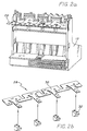
- Fig. 1 is a perspective view of a thermal inkjet desktop printer incorporating the teachings of the present invention.
- the printer 10 includes a housing 11a and a protective front access lid 11b .
- a carriage assembly 18 which has four inkjet pens 22 , is adapted for reciprocal motion along carriage bar 15 .
- the position of the carriage assembly 18 in the carriage scan axis along carriage bar 15 is determined by a carriage positioning mechanism (not shown) on the carriage assembly 18 that senses its position relative to carriage encoder strip 17 .
- An input tray 19a holds an media input stack 13 and after printing the printed media is held by an output tray 19b .
- a color inkjet printer/plotter has four inkjet pens 22 , one that stores black ink, and three that store colored inks, e.g., magenta, cyan and yellow. The colors from the three color pens are mixed to obtain any particular color.
- FIG. 1b is a detailed illustration of an inkjet pen 22 that includes heater circuits, which when activated cause ink to be ejected from the inkjet pen 22 at end 26 .
- FIG. 1c illustrates carriage assembly 18 including four inkjet pens 22 installed in four pen stalls 16 in unitary housing 12 with cover 24 placed on top.
- the inkjet pens 22 are held in unitary housing 12 by unitary spring clamp assembly 28 , which is installed onto unitary housing 12 , as shown in FIG. 2a.
- the tops of the inkjet pens 22 are retained by cam clamps 32 on unitary spring clamp assembly 28 when the inkjet pens 22 are inserted into unitary housing 12 .
- FIG. 2b shows the position of cam clamps 32 on spring 30 to form unitary spring clamp assembly 28 .
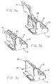
- unitary clamp assembly 28 is installed onto unitary housing 12 , as shown in FIG. 2a, then removable frame circuit assembly 14 is placed into unitary housing 12 , as shown in FIGs. 3a and 3b. Removable frame circuit assembly 14 is fastened to unitary housing 12 with a single attachment device 20 , as shown in FIG 3c.
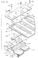
- FIG. 4 is an illustrative diagram showing a detailed view of the unitary housing 12 in accordance with the present invention.
- the unitary housing 12 is a one piece construction and retains the inkjet pens in a fixed relation to each other and the inkjet printer.
- a first portion 47 integral to the unitary housing extends along a first axis and is adapted to engage the carriage bar 15 .
- the pen stalls 16 each extend along a second axis and are substantially transverse to and integral with the first portion 47 .
- Rear compartment 38 extending along a third axis, is substantially transverse to and integral with the first and second portions and adapted to retain a substantially planar frame circuit assembly 14 within a plane defined by the first and third axes.
- the unitary housing provides a substantially smaller carriage assembly than the prior art.
- the unitary housing 12 has a front wall 41 , two lateral walls 42 , three pen stall walls 44 , and rear wall 43 , which form four pen stalls 16 . It also has a rear compartment 38 formed by lateral walls 42 , rear wall 43 , base 45 , and the spaces between pen stall walls 44 closest to base 45 .
- the four pen stalls 16 have passages that communicate to the rear stall between rear wall 43 and base 45 and between the pen stall walls 44 .
- the removable frame circuit assembly 14 is installed into the rear compartment 38 in unitary housing 12 , as shown in FIGs. 3a - 3c.
- the single attachment device 20 which can be a simple screw, mates with single attachment point 40 on unitary housing 12 to attach removable frame circuit assembly 14 to unitary housing 12 .
- the removable frame circuit assembly 14 needs to be properly aligned to the unitary housing 12 , because there are electrical contacts on the inkjet pens that when mounted in pen stalls 16 must make proper electrical contact with electrical contacts on the removable frame circuit assembly 14 .
- the alignment of removable frame circuit assembly 14 to unitary housing 12 is provided by two vertical alignment pins 46 for vertical alignment and by single horizontal alignment wall 48 for horizontal alignment.
- the vertical alignment pins 46 mate with alignment holes 68 on removable frame circuit assembly 14 , shown in FIG. 5b.
- the single horizontal alignment wall 48 is a vertical wall in unitary housing 12 .
- Alignment slot 70 on removable frame circuit assembly 14 shown in FIG. 5b, slides over and aligns to single horizontal alignment wall 48 when the removable frame circuit assembly 14 is assembled with unitary housing 12 .
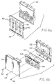
- FIGs. 5a and 5b are illustrative diagrams showing the assembly of a unitary frame 52 with circuit board 54 and unitary interconnect 56 to form removable frame circuit assembly 14 in accordance with the present invention.
- the unitary interconnect 56 is aligned to unitary frame 52 by alignment pins 64 and unitary interconnect alignment pins 66 on unitary frame 52 that fit into alignment holes 108 and alignment holes 110 , respectively, on unitary interconnect 56 as shown in FIG. 7.
- the unitary interconnect 56 is wrapped over extensions 78 that are on one end of unitary frame 52 .
- the unitary interconnect 56 provides a shorter interconnect between the inkjet pens 22 and the circuit board 54 than the separate flexible circuits for each inkjet pen of the prior art, which is partially a result of the substantially smaller carriage assembly provided by unitary housing 12 .
- the unitary interconnect 56 has two areas of electrical contacts: electrical contacts 60 on unitary interconnect first end 74 and electrical contacts 62 on unitary interconnect second end 75 .
- the electrical contacts 62 interconnect with circuit board 54 .
- the electrical contacts 60 are for electrical interconnection with the inkjet pens 22 held in pen stalls 16 .
- the circuit board 54 is attached to the unitary frame 52 with devices such as screws 58 that pass through circuit board attachment holes 57 and unitary interconnect holes 59 and into unitary frame 52 .
- the single attachment device 20 passes through circuit board attachment hole 61 and unitary frame hole 63 , when attaching removable frame circuit assembly 14 to unitary housing 12 .
- FIGs. 6a and 6b are illustrative diagrams showing the assembly of unitary interconnect 56 on unitary frame 52 and circuit board 54 to form a removable frame circuit assembly 14 in accordance with the present invention.
- the unitary interconnect 56 is first aligned and attached to unitary frame 52 .
- an elastomeric pad 124 is placed into recess 130 in unitary frame 52 and then the unitary interconnect 56 is wrapped over one end of unitary frame 52 and the electrical contacts 62 are aligned onto unitary frame 52 and over the elastomeric pad 124 .
- the circuit board 54 is attached to the unitary frame 52 to make electrical contact with electrical contacts 62 on unitary interconnect 56 .
- the electrical interconnection of the unitary interconnect 56 with the circuit board 54 is described in further detail with reference to FIG. 10 later in this specification.
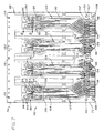
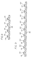
- FIG. 7 is an illustrative detailed diagram of the unitary interconnect 56 constructed in accordance with the present invention.
- the unitary interconnect 56 includes substrate 88 , which for convenience of description has a unitary interconnect first end 74 and a unitary interconnect second end 75 . As discussed above, there are alignment holes 108 and alignment holes 110 on substrate 88 for alignment to the unitary frame 52 .
- each identical individual set of electrical signal and ground contacts 90 in FIG. 7 has twenty three electrical signal contacts 94 and nine electrical ground contacts 96 .
- the electrical contacts 60 of FIG. 5b are simplified representations of the electrical signal contacts 94 and electrical ground contacts 96 , as shown more accurately in FIG. 7.
- the electrical contacts 62 of FIG. 5a are simplified representations of the electrical signal contacts 100 and electrical ground contacts 102 , as shown more accurately in FIG. 7.
- the number of heater circuits that are activated at any one time are determined by the pattern being printed.
- the advantage of the design for unitary interconnect 56 is that a common conductive ground layer 122 is used to interconnect the nine electrical ground contacts 96 for each of the four identical individual sets of electrical signal and ground contacts 90 to all sixteen electrical ground contacts 102 .
- a total of thirty six electrical ground contacts 96 are interconnected via common conductive ground layer 122 with sixteen electrical ground contacts 102 .
- each inkjet pen can use all sixteen electrical ground contacts 102 for a ground return. Sharing the ground contacts reduces ground fluctuations for the inkjet pens and improves their performance.
- each inkjet pen has a reduced number of electrical ground contacts, which can cause ground fluctuations if a large number of heater circuits are activated in one inkjet pen.
- FIG. 8 is an illustrative diagram of section 8-8 of FIG. 7 showing protrusions 116 on substrate 88 constructed in accordance with the present invention. As shown in FIG. 8, there are electrical signal contacts 94 or electrical ground contacts 96 on protrusions 116 .
- FIG. 9 is an illustrative diagram of section 9-9 of FIG. 7 showing protrusions 118 on substrate 88 . As shown in FIG. 9, there are electrical signal contacts 100 or electrical ground contacts 102 on protrusions 118 . The electrical contacts on protrusions 116 make contact with electrical contacts on the inkjet pens 22 and the electrical contacts on protrusions 118 make contact with electrical contacts on circuit board 54 .
- FIG. 10 an electrical interconnect system 140 for a flexible circuit with a circuit board is shown.
- the unitary interconnect 56 shown in detail in FIG. 7, is constructed with a polyester or polyimide material such as Mylar or Kapton substrate 88 onto which multiple conductors are deposited.
- the conductors are made of copper and can be covered with another layer of Mylar or Kapton.
- Electrical contacts 62 are located on protrusions 118 on substrate 88 , as shown in FIG. 9.
- FIG. 11 shows the opposite side of circuit board 54 with circuit board contacts 134 , which are interconnected with electrical contacts 62 on unitary interconnect 56 .
- the arrangement of circuit board contacts 134 on circuit board 54 correspond to the arrangement of electrical contacts 62 on unitary interconnect 56 , which is shown in detail in FIG. 7.
- Each of the circuit board contacts 134 are gold plated and the electrical contacts 62 are also gold plated to insure a low resistance electrical path.
- the circuit board 54 and unitary interconnect 56 are assembled on a unitary frame 52 , which can be constructed of plastic, because only low pressure is used to interconnect circuit board contacts 134 and electrical contacts 62 .
- An elastomeric pad 124 which can be constructed of urethane rubber, provides a spring function and is mounted into recess 130 in unitary frame 52 .
- the electrical interconnect system 140 is assembled by using screws 58 that are inserted through circuit board attachment hole 57 on circuit board 54 and unitary interconnect holes 59 on unitary interconnect 56 and then screwed into attachment holes 126 on unitary frame 52 .
- the electrical contacts 62 on unitary interconnect 56 are aligned to circuit board contacts 134 on circuit board 54 by alignment pins 64 coupled to unitary frame 52 , which are inserted through alignment holes 108 on unitary interconnect 56 and alignment holes 72 on circuit board 54 .
- alignment pins 64 coupled to unitary frame 52 , which are inserted through alignment holes 108 on unitary interconnect 56 and alignment holes 72 on circuit board 54 .
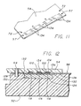
- FIG. 12 is an illustrative diagram of an elevation section along line 12-12 of FIG. 10 of an assembled electrical interconnect system for a flexible circuit.
- the elastomeric pad 124 is shown to fit within recess 130 in unitary frame 52 .
- the elastomeric pad 124 provides a spring function that bears upon the electrical contacts 100 on protrusions 118 between the elastomeric pad 124 and the circuit board 54 .
- the unitary frame 52 has bevels 132 between the recess 130 and the top surface 128 of the unitary frame 52 .
- each bevel 132 provides relief for allowing the unitary interconnect 56 to deform during assembly so that all of the electrical contacts 100 on protrusions 118 make contact with all of the circuit board contacts 134 on circuit board 54 .
- Bevels 132 provide relief to the portion of unitary interconnect 56 between elastomeric pad 124 and circuit board 54 .
- circuit contact recesses 136 which contain circuit board contacts 134 .
- the circuit contact recesses 136 on circuit board 54 are the result of a coating such as a solder mask that is applied over the conductors on circuit board 54 to protect the conductors from corrosion and to prevent solder bridging. This leaves slight circuit contact recesses 136 on the order of .001 - .002 inches deep at each of the circuit board contacts 134 , which as discussed above are gold plated.
- the portion of unitary interconnect 56 between elastomeric pad 124 and circuit board 54 deforms, which allows the protrusions 118 on unitary interconnect 56 to align with the circuit contact recesses 136 on circuit board 54 to ensure proper electrical contact.
- the electrical interconnect system for a flexible circuit 140 is easy to assemble and disassemble by simply loosening or tightening screws 58 .
- the interconnect density exceeds 150 contacts per square inch, which provides a high density interconnect system.
- the improved unitary interconnect system provides an interconnect system that reduces cost, is easier to assemble and align, and provides ground plane sharing for all of the inkjet pens.
- the carriage assembly has reduced cost and is easier to assemble, align and service without the need for any special tools.
Description
- This invention relates to carriage assemblies and more particularly to carriage assemblies for multiple inkjet pens in a color inkjet printer.
- Inkjet printer/plotters and desktop printers, such as those sold by Hewlett Packard Company, offer substantial improvements in speed over conventional X-Y plotters and printers. Inkjet printer/plotters typically include a pen having an array of nozzles. The pens are mounted on a carriage which is moved across the page in successive swaths. Each inkjet pen has heater circuits which, when activated, cause ink to be ejected from associated nozzles. As the pen is positioned over a given location, a jet of ink is ejected from the nozzle to provide a pixel of ink at a desired location. The mosaic of pixels thus created provides a desired composite image.
- Inkjet technology is now well known in the art. See, for example, U. S. Patents Nos. 4,872,027, entitled PRINTER HAVING IDENTIFIABLE INTERCHANGEABLE HEADS, issued October 3, 1989, to W. A. Buskirk et al. and 4,965,593, entitled PRINT QUALITY OF DOT PRINTERS, issued October 23, 1990, to M. S. Hickman. EP-A- 313205 discloses a print carriage adapted to hold a single ink jet cartridge.
- Recently, full color inkjet printer/plotters and desktop printers have been developed which comprise a plurality of inkjet pens of diverse colors. A typical color inkjet printer/plotter has four inkjet pens, one that stores black ink, and three that store colored inks, e.g., magenta, cyan and yellow. The colors from the three color pens are mixed to obtain any particular color.
- The pens are typically mounted in stalls within an assembly which is mounted on the carriage of the printer/plotter. The carriage assembly positions the inkjet pens and typically holds the circuitry required for interfacing to the heater circuits in the inkjet pens.
- Conventionally, a carriage assembly consists of four pen stalls to align the inkjet pens, four pen clamps to hold the inkjet pens in the pen stalls, a printed circuit board having the circuitry for interfacing to the heater circuits in the inkjet pens, and four separate flexible circuits interconnected between the printed circuit board and electrical contacts on the inkjet pens. Each of these separate parts are conventionally assembled piece by piece with screws fastening the parts individually to a housing to form a carriage assembly. Assembly of these individual parts is a difficult and expensive process and special tools are required to properly align the parts. The carriage assembly moves during printing and for quick responsiveness, it is required that the overall carriage assembly be lightweight, which results in a relatively fragile carriage assembly. If a conventional carriage assembly is accidentally bumped or one of its components fails, then repair for a conventional carriage assembly is costly, because of the multitude of individual parts and the difficult alignment process.
- Conventionally, in a carriage assembly, a separate flexible circuit is used to interconnect each inkjet pen to the associated printed circuit board. The flexible circuit is made with a polyester or polyimid material such as Mylar or Kapton onto which multiple conductors are deposited. A color inkjet printer with four inkjet pens requires four separate flexible circuits. The use of separate flexible circuits has the disadvantages of: 1) high cost, due to the need to manufacture and stock the separate flexible circuits; 2) difficulty of assembly, because of the need to route and precisely align in the carriage assembly each of the separate flexible circuits to each of the inkjet pen housings; and 3) cost of assembly because the separate flexible circuits need to be separately interconnected with the printed circuit board.
- The earlier, non-prepublished EP-A-581297 relates to a recording head unit of an inkjet recording apparatus.
The recording head unit has a top housing and side housings which are fixed on a unit frame. The unit frame has compartments for receiving the recording heads. On one of the major surfaces of the top housing, there are provided pads which function as electric contacts of the recording head unit. The pads are in connection with lead terminals which are in contact with associated connecting pads on a base plate of the recording heads. - Accordingly, there is a need in the art for a carriage assembly that has reduced cost and is easier to assemble, align and service.
- The need in the art is addressed by an improved carriage assembly for an inkjet printer of the present invention. The inventive assembly includes a carriage with at least two stalls molded therein for holding a plurality of inkjet pens. A removable frame is insertable into a compartment in the carriage adjacent to the stalls for holding an electrical circuit.
- In a specific embodiment an improved carriage of one piece construction for retaining at least two inkjet print cartridges in a fixed relation includes a first portion extending along a first axis and adapted to engage a carriage bar of an inkjet printer along the first axis. At least two second portions, each extending along a second axis, are substantially transverse to and integral with the first portion and retain the first and second inkjet print cartridges in a fixed relation. A third portion, extending along a third axis, is substantially transverse to and integral with the first and second portions and adapted to retain a substantially planar removable element within a plane defined by the first and third axes.
- The improved modular carriage assembly has reduced cost and is easier to assemble, align and service without the need for any special tools.
- FIGs. 1a through 1c are illustrative diagrams showing a thermal inkjet printer, inkjet pen and inkjet pens installed in a unitary housing in accordance with the present invention.
- FIGs. 2a and 2b are illustrative diagrams showing spring mechanisms for clamping the inkjet pens in a unitary housing in accordance with the present invention.
- FIGs. 3a through 3c are illustrative diagrams of an improved carriage assembly showing the coupling of a removable frame circuit assembly to a unitary housing in accordance with the present invention.
- FIG. 4 is an illustrative diagram showing a unitary housing in accordance with the present invention.
- FIGs. 5a and 5b are illustrative diagrams showing the assembly of a unitary frame with a circuit board and unitary interconnect to form a removable frame circuit assembly in accordance with the present invention.
- FIGs. 6a and 6b are illustrative diagrams showing the assembly of a unitary interconnect on a unitary frame with a circuit board to form a removable frame circuit assembly in accordance with the present invention.
- FIG. 7 is an illustrative diagram of a unitary interconnect system constructed in accordance with the present invention.
- FIG. 8 is an illustrative diagram of section 8-8 of FIG. 7 showing protrusions on the unitary interconnect system for electrical signal and electrical ground contacts constructed in accordance with the present invention.
- FIG. 9 is an illustrative diagram of section 9-9 of FIG. 7 showing protrusions on the unitary interconnect system for electrical signal and electrical ground contacts constructed in accordance with the present invention.
- FIG. 10 is an illustrative diagram of a disassembled electrical interconnect system for a unitary interconnect.
- FIG. 11 is an illustrative diagram showing contacts on a circuit board corresponding to contacts on a unitary interconnect.
- FIG. 12 is an illustrative diagram of an elevation section along line 12-12 of FIG. 10 of an assembled electrical interconnect system for a unitary interconnect.
- Illustrative embodiments and exemplary applications will now be described with reference to the accompanying drawings to disclose the advantageous teachings of the present invention.
- Fig. 1 is a perspective view of a thermal inkjet desktop printer incorporating the teachings of the present invention. The
printer 10 includes a housing 11a and a protective front access lid 11b. Acarriage assembly 18, which has fourinkjet pens 22, is adapted for reciprocal motion alongcarriage bar 15. The position of thecarriage assembly 18 in the carriage scan axis alongcarriage bar 15 is determined by a carriage positioning mechanism (not shown) on thecarriage assembly 18 that senses its position relative tocarriage encoder strip 17. An input tray 19a holds anmedia input stack 13 and after printing the printed media is held by anoutput tray 19b. - A color inkjet printer/plotter has four
inkjet pens 22, one that stores black ink, and three that store colored inks, e.g., magenta, cyan and yellow. The colors from the three color pens are mixed to obtain any particular color. FIG. 1b is a detailed illustration of aninkjet pen 22 that includes heater circuits, which when activated cause ink to be ejected from theinkjet pen 22 atend 26. FIG. 1c illustratescarriage assembly 18 including fourinkjet pens 22 installed in fourpen stalls 16 inunitary housing 12 withcover 24 placed on top. - The inkjet pens 22 are held in
unitary housing 12 by unitaryspring clamp assembly 28, which is installed ontounitary housing 12, as shown in FIG. 2a. The tops of the inkjet pens 22 are retained by cam clamps 32 on unitaryspring clamp assembly 28 when the inkjet pens 22 are inserted intounitary housing 12. FIG. 2b shows the position of cam clamps 32 onspring 30 to form unitaryspring clamp assembly 28. - After
unitary clamp assembly 28 is installed ontounitary housing 12, as shown in FIG. 2a, then removableframe circuit assembly 14 is placed intounitary housing 12, as shown in FIGs. 3a and 3b. Removableframe circuit assembly 14 is fastened tounitary housing 12 with asingle attachment device 20, as shown in FIG 3c. - FIG. 4 is an illustrative diagram showing a detailed view of the
unitary housing 12 in accordance with the present invention. Theunitary housing 12 is a one piece construction and retains the inkjet pens in a fixed relation to each other and the inkjet printer. Afirst portion 47 integral to the unitary housing extends along a first axis and is adapted to engage thecarriage bar 15. The pen stalls 16 each extend along a second axis and are substantially transverse to and integral with thefirst portion 47.Rear compartment 38, extending along a third axis, is substantially transverse to and integral with the first and second portions and adapted to retain a substantially planarframe circuit assembly 14 within a plane defined by the first and third axes. The unitary housing provides a substantially smaller carriage assembly than the prior art. - The
unitary housing 12 has afront wall 41, twolateral walls 42, threepen stall walls 44, andrear wall 43, which form four pen stalls 16. It also has arear compartment 38 formed bylateral walls 42,rear wall 43,base 45, and the spaces betweenpen stall walls 44 closest tobase 45. The fourpen stalls 16 have passages that communicate to the rear stall betweenrear wall 43 andbase 45 and between thepen stall walls 44. The removableframe circuit assembly 14 is installed into therear compartment 38 inunitary housing 12, as shown in FIGs. 3a - 3c. Thesingle attachment device 20, which can be a simple screw, mates withsingle attachment point 40 onunitary housing 12 to attach removableframe circuit assembly 14 tounitary housing 12. - The removable
frame circuit assembly 14 needs to be properly aligned to theunitary housing 12, because there are electrical contacts on the inkjet pens that when mounted in pen stalls 16 must make proper electrical contact with electrical contacts on the removableframe circuit assembly 14. The alignment of removableframe circuit assembly 14 tounitary housing 12 is provided by two vertical alignment pins 46 for vertical alignment and by singlehorizontal alignment wall 48 for horizontal alignment. The vertical alignment pins 46 mate withalignment holes 68 on removableframe circuit assembly 14, shown in FIG. 5b. The singlehorizontal alignment wall 48 is a vertical wall inunitary housing 12. Alignment slot 70 on removableframe circuit assembly 14, shown in FIG. 5b, slides over and aligns to singlehorizontal alignment wall 48 when the removableframe circuit assembly 14 is assembled withunitary housing 12. - FIGs. 5a and 5b are illustrative diagrams showing the assembly of a
unitary frame 52 withcircuit board 54 andunitary interconnect 56 to form removableframe circuit assembly 14 in accordance with the present invention. Theunitary interconnect 56 is aligned tounitary frame 52 byalignment pins 64 and unitary interconnect alignment pins 66 onunitary frame 52 that fit intoalignment holes 108 andalignment holes 110, respectively, onunitary interconnect 56 as shown in FIG. 7. Theunitary interconnect 56 is wrapped overextensions 78 that are on one end ofunitary frame 52. When theframe circuit assembly 14 is installed intounitary housing 12, thenextensions 78 slide into the passages betweenpen stall walls 44 andrear wall 43 and behindbase 45, which positionselectrical contacts 60 for interconnection with electrical contacts on the inkjet pens 22. - The
unitary interconnect 56 provides a shorter interconnect between the inkjet pens 22 and thecircuit board 54 than the separate flexible circuits for each inkjet pen of the prior art, which is partially a result of the substantially smaller carriage assembly provided byunitary housing 12. - The
unitary interconnect 56 has two areas of electrical contacts:electrical contacts 60 on unitary interconnectfirst end 74 andelectrical contacts 62 on unitary interconnectsecond end 75. Theelectrical contacts 62 interconnect withcircuit board 54. Theelectrical contacts 60 are for electrical interconnection with the inkjet pens 22 held in pen stalls 16. As shown in FIG. 5a, thecircuit board 54 is attached to theunitary frame 52 with devices such asscrews 58 that pass through circuit board attachment holes 57 and unitary interconnect holes 59 and intounitary frame 52. Thesingle attachment device 20 passes through circuitboard attachment hole 61 andunitary frame hole 63, when attaching removableframe circuit assembly 14 tounitary housing 12. - FIGs. 6a and 6b are illustrative diagrams showing the assembly of
unitary interconnect 56 onunitary frame 52 andcircuit board 54 to form a removableframe circuit assembly 14 in accordance with the present invention. As shown in FIG. 6a, theunitary interconnect 56 is first aligned and attached tounitary frame 52. Then, as shown in FIG. 6b, anelastomeric pad 124 is placed intorecess 130 inunitary frame 52 and then theunitary interconnect 56 is wrapped over one end ofunitary frame 52 and theelectrical contacts 62 are aligned ontounitary frame 52 and over theelastomeric pad 124. Finally, thecircuit board 54 is attached to theunitary frame 52 to make electrical contact withelectrical contacts 62 onunitary interconnect 56. The electrical interconnection of theunitary interconnect 56 with thecircuit board 54 is described in further detail with reference to FIG. 10 later in this specification. - FIG. 7 is an illustrative detailed diagram of the
unitary interconnect 56 constructed in accordance with the present invention. Theunitary interconnect 56 includessubstrate 88, which for convenience of description has a unitary interconnectfirst end 74 and a unitary interconnectsecond end 75. As discussed above, there arealignment holes 108 andalignment holes 110 onsubstrate 88 for alignment to theunitary frame 52. - Along unitary interconnect
first end 74 ofsubstrate 88, there are four identical individual sets of electrical signal andground contacts 90 that are for interconnection to the signal contacts on an inkjet pen. Each identical individual set of electrical signal andground contacts 90 in FIG. 7 has twenty threeelectrical signal contacts 94 and nineelectrical ground contacts 96. Theelectrical contacts 60 of FIG. 5b are simplified representations of theelectrical signal contacts 94 andelectrical ground contacts 96, as shown more accurately in FIG. 7. - At unitary substrate
second end 75 ofsubstrate 88, there are four individual sets ofelectrical signal contacts 98, which each have twenty threeelectrical signal contacts 100. The four individual sets ofelectrical traces 104, which each include twenty threeelectrical traces 106, interconnect the twenty threeelectrical signal contacts 94 of each of the identical individual sets of electrical signal andground contacts 90 to the individual sets ofelectrical signal contacts 98. There are sixteen totalelectrical ground contacts 102 along the unitary interconnectsecond end 75 ofsubstrate 88. Theelectrical contacts 62 of FIG. 5a are simplified representations of theelectrical signal contacts 100 andelectrical ground contacts 102, as shown more accurately in FIG. 7. - In an inkjet printer the number of heater circuits that are activated at any one time are determined by the pattern being printed. The advantage of the design for
unitary interconnect 56 is that a commonconductive ground layer 122 is used to interconnect the nineelectrical ground contacts 96 for each of the four identical individual sets of electrical signal andground contacts 90 to all sixteenelectrical ground contacts 102. Thus, a total of thirty sixelectrical ground contacts 96 are interconnected via commonconductive ground layer 122 with sixteenelectrical ground contacts 102. This solves the problem of having limited interconnect area at unitary interconnectsecond end 75 for theelectrical ground contacts 102 and allows sharing of all theelectrical ground contacts 102 for theelectrical ground contacts 96 of all of the inkjet pens. Thus, if a large number of heater circuits in oneinkjet pen 22 are activated, then that inkjet pen can use all sixteenelectrical ground contacts 102 for a ground return. Sharing the ground contacts reduces ground fluctuations for the inkjet pens and improves their performance. In a conventional device there is a separate interconnect flexible circuit for eachinkjet pen 22 and therefore separate ground returns for each inkjet pen. Thus, in the conventional device each inkjet pen has a reduced number of electrical ground contacts, which can cause ground fluctuations if a large number of heater circuits are activated in one inkjet pen. - FIG. 8 is an illustrative diagram of section 8-8 of FIG. 7 showing
protrusions 116 onsubstrate 88 constructed in accordance with the present invention. As shown in FIG. 8, there areelectrical signal contacts 94 orelectrical ground contacts 96 onprotrusions 116. Similarly, FIG. 9 is an illustrative diagram of section 9-9 of FIG. 7 showingprotrusions 118 onsubstrate 88. As shown in FIG. 9, there areelectrical signal contacts 100 orelectrical ground contacts 102 onprotrusions 118. The electrical contacts onprotrusions 116 make contact with electrical contacts on the inkjet pens 22 and the electrical contacts onprotrusions 118 make contact with electrical contacts oncircuit board 54. - In FIG. 10 an
electrical interconnect system 140 for a flexible circuit with a circuit board is shown. Theunitary interconnect 56, shown in detail in FIG. 7, is constructed with a polyester or polyimide material such as Mylar orKapton substrate 88 onto which multiple conductors are deposited. The conductors are made of copper and can be covered with another layer of Mylar or Kapton.Electrical contacts 62 are located onprotrusions 118 onsubstrate 88, as shown in FIG. 9. - FIG. 11 shows the opposite side of
circuit board 54 withcircuit board contacts 134, which are interconnected withelectrical contacts 62 onunitary interconnect 56. The arrangement ofcircuit board contacts 134 oncircuit board 54 correspond to the arrangement ofelectrical contacts 62 onunitary interconnect 56, which is shown in detail in FIG. 7. Each of thecircuit board contacts 134 are gold plated and theelectrical contacts 62 are also gold plated to insure a low resistance electrical path. - As shown in FIG. 10, the
circuit board 54 andunitary interconnect 56 are assembled on aunitary frame 52, which can be constructed of plastic, because only low pressure is used to interconnectcircuit board contacts 134 andelectrical contacts 62. Anelastomeric pad 124, which can be constructed of urethane rubber, provides a spring function and is mounted intorecess 130 inunitary frame 52. Theelectrical interconnect system 140 is assembled by usingscrews 58 that are inserted through circuitboard attachment hole 57 oncircuit board 54 and unitary interconnect holes 59 onunitary interconnect 56 and then screwed into attachment holes 126 onunitary frame 52. Theelectrical contacts 62 onunitary interconnect 56 are aligned tocircuit board contacts 134 oncircuit board 54 byalignment pins 64 coupled tounitary frame 52, which are inserted throughalignment holes 108 onunitary interconnect 56 and alignment holes 72 oncircuit board 54. When the electrical interconnect system is assembled theelectrical contacts 62 are aligned and have electrical contact withcircuit board contacts 134. - FIG. 12 is an illustrative diagram of an elevation section along line 12-12 of FIG. 10 of an assembled electrical interconnect system for a flexible circuit. In FIG. 12 the
elastomeric pad 124 is shown to fit withinrecess 130 inunitary frame 52. Theelastomeric pad 124 provides a spring function that bears upon theelectrical contacts 100 onprotrusions 118 between theelastomeric pad 124 and thecircuit board 54. Theunitary frame 52 hasbevels 132 between therecess 130 and thetop surface 128 of theunitary frame 52. The object of eachbevel 132 is to provide relief for allowing theunitary interconnect 56 to deform during assembly so that all of theelectrical contacts 100 onprotrusions 118 make contact with all of thecircuit board contacts 134 oncircuit board 54. As thescrews 58 are tightened, a portion of theunitary interconnect 56 is clamped between thetop surface 128 ofunitary frame 52 and thecircuit board 54.Bevels 132 provide relief to the portion ofunitary interconnect 56 betweenelastomeric pad 124 andcircuit board 54. - Also shown in FIG. 12 are circuit contact recesses 136, which contain
circuit board contacts 134. The circuit contact recesses 136 oncircuit board 54 are the result of a coating such as a solder mask that is applied over the conductors oncircuit board 54 to protect the conductors from corrosion and to prevent solder bridging. This leaves slight circuit contact recesses 136 on the order of .001 - .002 inches deep at each of thecircuit board contacts 134, which as discussed above are gold plated. During assembly, the portion ofunitary interconnect 56 betweenelastomeric pad 124 andcircuit board 54 deforms, which allows theprotrusions 118 onunitary interconnect 56 to align with the circuit contact recesses 136 oncircuit board 54 to ensure proper electrical contact. - The electrical interconnect system for a
flexible circuit 140 is easy to assemble and disassemble by simply loosening or tightening screws 58. The interconnect density exceeds 150 contacts per square inch, which provides a high density interconnect system. These desirable features are obtained while maintaining low cost and high reliability. - The improved unitary interconnect system provides an interconnect system that reduces cost, is easier to assemble and align, and provides ground plane sharing for all of the inkjet pens.
- The carriage assembly has reduced cost and is easier to assemble, align and service without the need for any special tools.
- Thus, the present invention has been described herein with reference to a particular embodiment for a particular application. Nonetheless, those having ordinary skill in the art and access to present teachings will recognize additional modifications, applications, and embodiments within the scope thereof. For example, the alignment pins of the present invention may be replaced by other equivalent devices without departing from the scope of the present invention.
Claims (2)
- A modular carriage assembly (12) for retaining at least two inkjet pens in a fixed relation comprising:a first portion (47) extending along a first axis and adapted to engage a carriage bar (15) of an inkjet printer along said first axis;at least two second portions (16), each extending along a second axis, substantially transverse to and integral with said first portion (47), for retaining said first and second inkjet pens (22) in a fixed relation; anda third portion (38), extending along a third axis, substantially transverse to and integral with said first portion (47) and second portions (16) and adapted to retain a removable frame (14) within a plane defined by said first and third axes (14), wherein the removable frame (14) having at least two extensions (78) molded thereon is separable from said inkjet pens for holding an electrical circuit means (56) insertable into said third portion, wherein when said removable frame (14) is inserted into said third portion each of said extensions is inserted into a respective said second portion.
- The modular carriage assembly (12) of claim 1 further comprising:a printed circuit (54) coupled to said removable frame (14) for interfacing to said inkjet pens (22); andan interconnect circuit (56) coupled to said printed circuit (54) and wrapped around said extensions (78) for interconnecting said printed circuit (54) to said inkjet pens (22).
Applications Claiming Priority (3)
| Application Number | Priority Date | Filing Date | Title |
|---|---|---|---|
| US5561893A | 1993-04-30 | 1993-04-30 | |
| US55618 | 1993-04-30 | ||
| EP93120341A EP0622240B1 (en) | 1993-04-30 | 1993-12-16 | Modular carriage assembly for an ink jet printer |
Related Parent Applications (2)
| Application Number | Title | Priority Date | Filing Date |
|---|---|---|---|
| EP93120341.8 Division | 1993-12-16 | ||
| EP93120341A Division EP0622240B1 (en) | 1993-04-30 | 1993-12-16 | Modular carriage assembly for an ink jet printer |
Publications (3)
| Publication Number | Publication Date |
|---|---|
| EP0807529A2 EP0807529A2 (en) | 1997-11-19 |
| EP0807529A3 EP0807529A3 (en) | 1998-02-11 |
| EP0807529B1 true EP0807529B1 (en) | 2000-07-12 |
Family
ID=21999057
Family Applications (2)
| Application Number | Title | Priority Date | Filing Date |
|---|---|---|---|
| EP93120341A Expired - Lifetime EP0622240B1 (en) | 1993-04-30 | 1993-12-16 | Modular carriage assembly for an ink jet printer |
| EP97113771A Expired - Lifetime EP0807529B1 (en) | 1993-04-30 | 1993-12-16 | A carriage assembly retaining two inkjet print cartridges |
Family Applications Before (1)
| Application Number | Title | Priority Date | Filing Date |
|---|---|---|---|
| EP93120341A Expired - Lifetime EP0622240B1 (en) | 1993-04-30 | 1993-12-16 | Modular carriage assembly for an ink jet printer |
Country Status (4)
| Country | Link |
|---|---|
| US (1) | US5539436A (en) |
| EP (2) | EP0622240B1 (en) |
| JP (1) | JP3420637B2 (en) |
| DE (2) | DE69319092T2 (en) |
Families Citing this family (25)
| Publication number | Priority date | Publication date | Assignee | Title |
|---|---|---|---|---|
| US6084617A (en) * | 1995-10-31 | 2000-07-04 | Hewlett-Packard Company | Narrow body inkjet print cartridge having parallel configuration of internal components |
| KR100195908B1 (en) * | 1996-10-28 | 1999-06-15 | 윤종용 | Head structure of inkjet printer |
| EP0890442A1 (en) * | 1997-06-18 | 1999-01-13 | Hewlett-Packard Company | Inkjet pen alignment mechanism and method |
| FR2773248B1 (en) * | 1997-12-30 | 2000-03-17 | Neopost Ind | SECURE DIGITAL POSTAL PRINTING MODULE |
| US6082854A (en) * | 1998-03-16 | 2000-07-04 | Hewlett-Packard Company | Modular ink-jet hard copy apparatus and methodology |
| EP0953456A1 (en) * | 1998-04-29 | 1999-11-03 | Hewlett-Packard Company | Integrated reciprocating cartridge architecture with integral bearings |
| US6224192B1 (en) | 1998-10-06 | 2001-05-01 | Hewlett-Packard Company | Inkjet printing systems using a modular print cartridge assembly |
| US6065826A (en) * | 1998-10-06 | 2000-05-23 | Hewlett-Packard Company | Modular print cartridge receptacle for use in inkjet printing systems |
| US6280017B1 (en) * | 1998-10-27 | 2001-08-28 | Canon Kabushiki Kaisha | Recording apparatus |
| USD430897S (en) * | 1999-06-11 | 2000-09-12 | Lexmark International, Inc. | Ink cartridge for printer |
| US6120201A (en) * | 1999-07-12 | 2000-09-19 | Hewlett-Packard Company | Printer with front portion providing access to print mechanism |
| US6386681B1 (en) | 2000-02-01 | 2002-05-14 | Lexmark International, Inc. | Carrier assembly and ink jet printhead assembly associated therewith |
| US6199977B1 (en) | 2000-04-13 | 2001-03-13 | Lexmark International, Inc. | Cartridge body for ink jet printer |
| US6729714B2 (en) * | 2001-07-31 | 2004-05-04 | Hewlett-Packard Development Company, L.P. | Separable key for establishing detachable printer component compatibility with a printer |
| JP2003182113A (en) * | 2001-10-12 | 2003-07-03 | Ricoh Co Ltd | Color ink jet recorder and copy machine |
| US20030202062A1 (en) * | 2002-04-25 | 2003-10-30 | Steinmetz Charles R. | Configurable ink supply system |
| US6715857B2 (en) | 2002-09-05 | 2004-04-06 | Lexmark International, Inc. | Printhead carrier housing and flexible printed circuit attached to same |
| JP3807359B2 (en) * | 2002-10-30 | 2006-08-09 | セイコーエプソン株式会社 | Liquid ejector |
| EP1418054B1 (en) * | 2002-11-07 | 2006-08-09 | Océ-Technologies B.V. | Print carriage assembly and method for mounting a print head holder thereon |
| JP4563019B2 (en) * | 2002-11-07 | 2010-10-13 | オセ−テクノロジーズ ビーブイ | Print carriage assembly and method for installing a printer head holder in the assembly |
| JP4161213B2 (en) * | 2004-01-23 | 2008-10-08 | ブラザー工業株式会社 | Wiring board bonding structure in ink jet recording head and bonding method thereof |
| KR100584611B1 (en) * | 2004-11-27 | 2006-06-01 | 삼성전자주식회사 | Inkjet printer |
| JP4726156B2 (en) * | 2005-02-24 | 2011-07-20 | 株式会社リコー | Image forming apparatus |
| CN102300713B (en) * | 2009-01-30 | 2014-05-07 | 惠普开发有限公司 | Flexible circuit |
| KR101278331B1 (en) * | 2010-10-07 | 2013-06-25 | 삼성전기주식회사 | The jig for round solder ball attachment |
Family Cites Families (12)
| Publication number | Priority date | Publication date | Assignee | Title |
|---|---|---|---|---|
| US4074284A (en) * | 1976-06-07 | 1978-02-14 | Silonics, Inc. | Ink supply system and print head |
| DE3313436A1 (en) * | 1982-04-19 | 1983-10-20 | Canon K.K., Tokyo | RECORDING DEVICE |
| US4827294A (en) * | 1985-11-22 | 1989-05-02 | Hewlett-Packard Company | Thermal ink jet printhead assembly employing beam lead interconnect circuit |
| US4806106A (en) * | 1987-04-09 | 1989-02-21 | Hewlett-Packard Company | Interconnect lead frame for thermal ink jet printhead and methods of manufacture |
| US4755836A (en) * | 1987-05-05 | 1988-07-05 | Hewlett-Packard Company | Printhead cartridge and carriage assembly |
| CA1304983C (en) * | 1987-10-23 | 1992-07-14 | David W. Pinkernell | Printhead-carriage alignment and electrical interconnect lock-in mechanism |
| US4872027A (en) * | 1987-11-03 | 1989-10-03 | Hewlett-Packard Company | Printer having identifiable interchangeable heads |
| US4878070A (en) * | 1988-10-17 | 1989-10-31 | Xerox Corporation | Thermal ink jet print cartridge assembly |
| JPH02198881A (en) * | 1989-01-27 | 1990-08-07 | Shimadzu Corp | Printer |
| US4940998A (en) * | 1989-04-04 | 1990-07-10 | Hewlett-Packard Company | Carriage for ink jet printer |
| US5359357A (en) * | 1992-03-19 | 1994-10-25 | Fuji Xerox Co., Ltd. | Ink-jet recording apparatus |
| EP0581297B1 (en) * | 1992-07-30 | 1999-03-17 | Canon Kabushiki Kaisha | Recording head unit and recording apparatus using same |
-
1993
- 1993-12-16 EP EP93120341A patent/EP0622240B1/en not_active Expired - Lifetime
- 1993-12-16 DE DE69319092T patent/DE69319092T2/en not_active Expired - Lifetime
- 1993-12-16 DE DE69329041T patent/DE69329041T2/en not_active Expired - Lifetime
- 1993-12-16 EP EP97113771A patent/EP0807529B1/en not_active Expired - Lifetime
-
1994
- 1994-04-13 JP JP09928494A patent/JP3420637B2/en not_active Expired - Fee Related
-
1995
- 1995-04-28 US US08/431,395 patent/US5539436A/en not_active Expired - Lifetime
Also Published As
| Publication number | Publication date |
|---|---|
| DE69329041D1 (en) | 2000-08-17 |
| EP0807529A2 (en) | 1997-11-19 |
| EP0622240A3 (en) | 1996-04-03 |
| JP3420637B2 (en) | 2003-06-30 |
| EP0622240B1 (en) | 1998-06-10 |
| US5539436A (en) | 1996-07-23 |
| DE69319092T2 (en) | 1999-01-07 |
| DE69319092D1 (en) | 1998-07-16 |
| JPH07125380A (en) | 1995-05-16 |
| EP0622240A2 (en) | 1994-11-02 |
| EP0807529A3 (en) | 1998-02-11 |
| DE69329041T2 (en) | 2001-03-22 |
Similar Documents
| Publication | Publication Date | Title |
|---|---|---|
| EP0807529B1 (en) | A carriage assembly retaining two inkjet print cartridges | |
| EP0622193B1 (en) | An improved unitary interconnect system for an inkjet printer | |
| US5533904A (en) | Electrical interconnect system for multiple flexible circuits | |
| EP0650848B1 (en) | Interconnect scheme for mounting differently configured print heads on the same carriage | |
| US5712669A (en) | Common ink-jet cartridge platform for different printheads | |
| US5257043A (en) | Thermal ink jet nozzle arrays | |
| US5971524A (en) | Alignment of differently sized printheads in a printer | |
| US6174046B1 (en) | Reliable contact pad arrangement on plastic print cartridge | |
| JPH07186411A (en) | Mixed-resolution printer | |
| US5883646A (en) | Compact flex-circuit for modular assembly of optical sensor components in an inkjet printer | |
| US6003974A (en) | Unitary interconnect system for an inkjet printer | |
| CN1265980A (en) | Inclined mounting ink cartridge for printer | |
| EP0820871B1 (en) | Ink jet type recording head | |
| EP0730975B1 (en) | Compliant interconnect assembly for mounting removable print cartridges in a carriage | |
| US5975679A (en) | Dot alignment in mixed resolution printer | |
| US20100149269A1 (en) | Modular Printhead Incorporating Alignment Mechanism For Printhead Module | |
| EP0730969B1 (en) | Dot alignment in mixed resolution printer | |
| JPH08108546A (en) | Ink jet recording apparatus | |
| JPH07195684A (en) | Ink jet printing bar that can be stacked with high accuracy and its production |
Legal Events
| Date | Code | Title | Description |
|---|---|---|---|
| PUAI | Public reference made under article 153(3) epc to a published international application that has entered the european phase |
Free format text: ORIGINAL CODE: 0009012 |
|
| 17P | Request for examination filed |
Effective date: 19970808 |
|
| AC | Divisional application: reference to earlier application |
Ref document number: 622240 Country of ref document: EP |
|
| AK | Designated contracting states |
Kind code of ref document: A2 Designated state(s): DE FR GB IT |
|
| PUAL | Search report despatched |
Free format text: ORIGINAL CODE: 0009013 |
|
| AK | Designated contracting states |
Kind code of ref document: A3 Designated state(s): DE FR GB IT |
|
| 17Q | First examination report despatched |
Effective date: 19990409 |
|
| GRAG | Despatch of communication of intention to grant |
Free format text: ORIGINAL CODE: EPIDOS AGRA |
|
| GRAG | Despatch of communication of intention to grant |
Free format text: ORIGINAL CODE: EPIDOS AGRA |
|
| GRAH | Despatch of communication of intention to grant a patent |
Free format text: ORIGINAL CODE: EPIDOS IGRA |
|
| GRAH | Despatch of communication of intention to grant a patent |
Free format text: ORIGINAL CODE: EPIDOS IGRA |
|
| ITF | It: translation for a ep patent filed |
Owner name: SOCIETA' ITALIANA BREVETTI S.P.A. |
|
| GRAA | (expected) grant |
Free format text: ORIGINAL CODE: 0009210 |
|
| AC | Divisional application: reference to earlier application |
Ref document number: 622240 Country of ref document: EP |
|
| AK | Designated contracting states |
Kind code of ref document: B1 Designated state(s): DE FR GB IT |
|
| REF | Corresponds to: |
Ref document number: 69329041 Country of ref document: DE Date of ref document: 20000817 |
|
| ET | Fr: translation filed | ||
| RAP2 | Party data changed (patent owner data changed or rights of a patent transferred) |
Owner name: HEWLETT-PACKARD COMPANY, A DELAWARE CORPORATION |
|
| PLBE | No opposition filed within time limit |
Free format text: ORIGINAL CODE: 0009261 |
|
| STAA | Information on the status of an ep patent application or granted ep patent |
Free format text: STATUS: NO OPPOSITION FILED WITHIN TIME LIMIT |
|
| 26N | No opposition filed | ||
| REG | Reference to a national code |
Ref country code: GB Ref legal event code: IF02 |
|
| REG | Reference to a national code |
Ref country code: GB Ref legal event code: 732E |
|
| REG | Reference to a national code |
Ref country code: FR Ref legal event code: TP |
|
| PGFP | Annual fee paid to national office [announced via postgrant information from national office to epo] |
Ref country code: IT Payment date: 20061231 Year of fee payment: 14 |
|
| PGFP | Annual fee paid to national office [announced via postgrant information from national office to epo] |
Ref country code: GB Payment date: 20071227 Year of fee payment: 15 Ref country code: FR Payment date: 20070207 Year of fee payment: 14 |
|
| REG | Reference to a national code |
Ref country code: FR Ref legal event code: ST Effective date: 20081020 |
|
| PG25 | Lapsed in a contracting state [announced via postgrant information from national office to epo] |
Ref country code: FR Free format text: LAPSE BECAUSE OF NON-PAYMENT OF DUE FEES Effective date: 20071231 |
|
| GBPC | Gb: european patent ceased through non-payment of renewal fee |
Effective date: 20081216 |
|
| PG25 | Lapsed in a contracting state [announced via postgrant information from national office to epo] |
Ref country code: IT Free format text: LAPSE BECAUSE OF NON-PAYMENT OF DUE FEES Effective date: 20071216 |
|
| PG25 | Lapsed in a contracting state [announced via postgrant information from national office to epo] |
Ref country code: GB Free format text: LAPSE BECAUSE OF NON-PAYMENT OF DUE FEES Effective date: 20081216 |
|
| PGFP | Annual fee paid to national office [announced via postgrant information from national office to epo] |
Ref country code: DE Payment date: 20121231 Year of fee payment: 20 |
|
| REG | Reference to a national code |
Ref country code: DE Ref legal event code: R071 Ref document number: 69329041 Country of ref document: DE |
|
| PG25 | Lapsed in a contracting state [announced via postgrant information from national office to epo] |
Ref country code: DE Free format text: LAPSE BECAUSE OF EXPIRATION OF PROTECTION Effective date: 20131217 |