EP0807523A2 - Printer - Google Patents
Printer Download PDFInfo
- Publication number
- EP0807523A2 EP0807523A2 EP97107925A EP97107925A EP0807523A2 EP 0807523 A2 EP0807523 A2 EP 0807523A2 EP 97107925 A EP97107925 A EP 97107925A EP 97107925 A EP97107925 A EP 97107925A EP 0807523 A2 EP0807523 A2 EP 0807523A2
- Authority
- EP
- European Patent Office
- Prior art keywords
- rollers
- paper
- cut
- insertion opening
- printing
- Prior art date
- Legal status (The legal status is an assumption and is not a legal conclusion. Google has not performed a legal analysis and makes no representation as to the accuracy of the status listed.)
- Granted
Links
Images


Classifications
-
- B—PERFORMING OPERATIONS; TRANSPORTING
- B41—PRINTING; LINING MACHINES; TYPEWRITERS; STAMPS
- B41J—TYPEWRITERS; SELECTIVE PRINTING MECHANISMS, i.e. MECHANISMS PRINTING OTHERWISE THAN FROM A FORME; CORRECTION OF TYPOGRAPHICAL ERRORS
- B41J11/00—Devices or arrangements of selective printing mechanisms, e.g. ink-jet printers or thermal printers, for supporting or handling copy material in sheet or web form
- B41J11/48—Apparatus for condensed record, tally strip, or like work using two or more papers, or sets of papers, e.g. devices for switching over from handling of copy material in sheet form to handling of copy material in continuous form and vice versa or point-of-sale printers comprising means for printing on continuous copy material, e.g. journal for tills, and on single sheets, e.g. cheques or receipts
-
- B—PERFORMING OPERATIONS; TRANSPORTING
- B41—PRINTING; LINING MACHINES; TYPEWRITERS; STAMPS
- B41J—TYPEWRITERS; SELECTIVE PRINTING MECHANISMS, i.e. MECHANISMS PRINTING OTHERWISE THAN FROM A FORME; CORRECTION OF TYPOGRAPHICAL ERRORS
- B41J13/00—Devices or arrangements of selective printing mechanisms, e.g. ink-jet printers or thermal printers, specially adapted for supporting or handling copy material in short lengths, e.g. sheets
- B41J13/26—Registering devices
- B41J13/28—Front lays, stops, or gauges
Definitions
- the present invention relates to a printer capable of printing on cut-sheet paper and, more particularly, to a point of sale (POS) printer for printing on cut-sheet paper, such as paper slips, bank checks etc..
- POS point of sale
- Printers that can print on cut-sheet paper, i.e., single sheets of paper, such as a paper voucher, a slip, a bank check or the like, are known.
- a sheet of paper is transferred to a printing area by a first pair of transfer rollers disposed adjacent a paper insertion opening (referred to as insertion rollers hereinafter).
- the sheet of paper is printed at a printing area and then discharged out of the printer by a second pair of transfer rollers disposed adjacent a paper discharge opening (referred to as discharge rollers hereinafter).
- discharge rollers For inserting a sheet of paper, the rollers are separated from each other to facilitate the insertion of the paper.
- slip printing When printing on relatively large sheet of paper, such as a slip (herein after referred to as slip printing), the paper is inserted through the insertion opening, passed through a paper feed path past the printing area, and discharged through the discharge opening.
- validation printing when printing a few lines in a predetermined area on card-like cut-sheet paper such as a bank check for payment validation (herein after referred to as validation printing), the paper is inserted through the discharge opening and printing is performed while the paper is transferred back toward the discharge opening past the printing area.
- slip will be used hereinafter as representative for any kind of cut-sheet paper suitable for slip printing and the term “check” will be used as representative for any kind of cut-sheet paper suitable for validation printing.
- Fig. 9 shows an explanatory view of a conventional printer that is capable of both slip printing and validation printing.
- Reference numeral 4 denotes a print head for printing on a slip 200 or a check 500 that is transferred to the printing area between print head 4 and a platen 38 by a pair of discharge rollers 19 and 20 and a pair of intermediate rollers 21 and 22, each pair being disposed in a manner that the rollers in each pair can be opened (separated from each other) and closed (brought together).
- Reference numeral 501 denotes a paper feed path for transferring a slip 200.
- a pair of insertion rollers (not shown) for slips is provided next to the insertion opening.
- the discharge rollers 19 and 20 and the intermediate rollers 21 and 22 are both separated from each other as shown in the figure, and the check 500 is inserted through the discharge opening down into a groove section 501a. Then, the discharge rollers 19 and 20 and the intermediate rollers 21 and 22 are both brought into pressure contact to pinch the check 500, and printing by the print head 4 is performed as the check is advanced upwardly back to the discharge opening.
- EP-B-0 428 163 discloses an impact dot matrix POS printer according to the precharacterizing part of claim 1, which differs from the one explained above with reference to Fig. 9 in that only the insertion rollers and the intermediate rollers but not the discharge rollers are provided.
- the platen and one of the intermediate rollers are supported on a first lever and one of the insertion rollers is supported on a second lever.
- the first lever is pivotally supported to close or open the intermediate rollers. When the intermediate rollers are open the printing area is also open, i.e., the platen is retracted from it working position opposite the print head.
- the second lever is also pivotally supported to close or open the insertion rollers.
- a first plunger is used to drive the first lever and a second plunger is used to drive the second lever. Both plungers are controlled in such a way that the insertion rollers and the intermediate rollers are either both open or both closed.
- EP-A-0 676 295 discloses a similar printer having a pair of discharge rollers and a pair of intermediate rollers.
- the structure is the same as that disclosed in the document EP-B-0 428 163.
- One of the discharge rollers is mounted on a second lever which in turn is pivotally mounted on the first lever supporting one of the intermediate rollers.
- the first lever is driven by a plunger to open the intermediate rollers
- the second lever is turned at the same time to open the discharge rollers.
- both the discharge rollers and the intermediate rollers can be driven together to be both open or both closed.
- the present invention is made to solve the above-described problems of the prior art. It is an object of the present invention to provide a printer capable of printing on a variety of types of cut-sheet paper in which a comparatively simple mechanism is used for opening/closing of transfer rollers and in which insertion of cut-sheet paper is facilitated and erroneous insertion prevented.
- Figs. 1 and 2 show the overall structure of a printer 1 in accordance with one embodiment of the present invention.
- the printer 1 has a main case 2 made of, for example, resin or the like.
- a roll S of paper is disposed in a rear part inside the main case 2.
- a paper transfer section 3 for transferring paper to be printed is mounted in a front part of the case 2.
- An ink jet printing section 4 for printing on the paper is disposed in front of the paper transfer section 3.
- the printing section 4 is covered by a front cover 5 made of resin or the like.
- the paper roll S, the paper transfer section 3 and the printing section 4 are mounted on a main frame 6 made of metal or the like.
- the printing section 4 is capable of moving between the lateral sides of the main frame 6 along a guide rail 7 fixed to the main frame 6.
- an ink jet head 4a of the printing section 4 is disposed opposite a platen section 8 that is provided in the paper transfer section 3.
- a printing area is defined between the ink jet head 4a and the platen section 8.
- the paper roll S is rotatably supported on a pair of support rollers 10 and 11 disposed in parallel with a roll core 9. The outer end of the paper roll S is drawn from the lower side of the printer toward the upper side.
- a paper path for the roll paper from paper roll S is formed in the paper transfer section 3. In other words, the roll paper is guided and transferred by a paper guide 12 and a roller 13 to the platen section 8. After printing on the roll paper by the printing section 4, the roll paper is further transferred by a roller 14 and discharged through a discharge opening 16 defined in an upper cover 15. When cut-sheet paper (described below) is not inserted, the roll paper can be printed.
- the upper cover 15 is rotatably mounted about a pivot axis 17.
- the platen section 8 is designed to move closer to and farther from the ink jet head 4a in association with the opening or closing of the upper cover 15.
- the platen section 8 and transfer roller 14 are supported on a frame which is rotatable about a shaft of the roller 13. This frame is connected to a lever 46 and is forced by a spring mounted on the lever 46 in a direction in which the platen section 8 and the roller 14 are moved away from the ink jet head 4a.
- the upper cover 15 and the front cover 5 define a discharge opening 18 in the upper central area of the printer for discharging cut-sheet paper (a slip 200 on which slip printing is performed or a check 500 on which validation printing is performed). As described below, the discharge opening 18 also serves as an insertion opening for validation printing.
- a set of discharge rollers 19 and 20 is disposed adjacent the discharge opening 18.
- a set of intermediate rollers 21 and 22 is disposed between the set of insertion rollers and the printing section 4, and a set of insertion rollers 23 and 24 is disposed below the printing section 4.
- These rollers and a pair of guide members 25 and 26 define a paper feed path for transferring a slip 200. As shown in Fig. 2, when slip printing is performed, a slip 200 is inserted into a paper insertion opening 27.
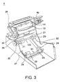
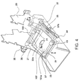
- Figs. 3 and 4 show the paper transfer section 3 in accordance with one embodiment of the present invention.
- each of the above mentioned sets of rollers in this embodiment comprises two pairs of rollers, each pair including a drive roller coupled to a drive source and an associated pinch roller.
- the two drive rollers of a respective set are fixed to the same shaft and the two pinch rollers have the same rotary axis. It is to be noted that the number of pairs of drive and pinch rollers in the respective sets of rollers is not critical to the invention.
- the rollers 13 and 14 for transferring roll paper are mounted on a metal support frame 28 substantially U-shaped in cross-section.
- the support frame 28 is mounted on a metal transfer frame 29 that forms a paper feed path for cut-sheet paper.
- the roller 13 for transferring roll paper is formed from a material that is not slippery, such as rubber or the like, and has a drive shaft 30 coupled to a drive motor (not shown).
- the roller 13 and the roller 14 are rotated in the same direction by a gear train (not shown).
- the support frame 28 is pivotally mounted about the drive shaft 30 of the roller 13.
- insertion rollers 23 for transferring a slip 200 are mounted on a shaft 31 that is rotatably mounted on an open/close lever 37. Also, intermediate rollers 21 are mounted on a shaft 100 that is rotatably mounted on the transfer frame 29.
- the insertion rollers 23 are driven by a drive pulley 32 that is driven by a motor (not shown), a belt 33 and a pulley 34.
- the intermediate rollers 21 are driven by a gear 35 that is driven by the above-described motor via a gear 36 that engages the gear 35.
- the open/close lever 37 is pivotally mounted on the transfer frame 29 about a shaft 32a having the drive pulley 32 mounted on one end thereof and the gear 35 on the other end.
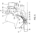
- Figs. 5 and 6 a cut-sheet transfer mechanism and its operation in the case of slip printing will be described. It is noted that the roll paper transfer mechanism shown in Fig. 1 is not shown in Figs. 5 and 6.
- the paper insertion opening 27 is defined by the upper and lower guide members 25 and 26 and guides a slip 200.
- the rollers 23 are separated from the rollers 24 and do not obstruct insertion of the slip 200.
- a tip section 101a of a stopper 101 protrudes from the lower guide member 25 into the paper feed path by the resilient force of a spring 103.
- a paper detector 102 is provided generally at the same location as the tip section 101a of the stopper 101. The paper detector 102 detects insertion of the slip 200.
- the detector 102 also detects the trailing end of the slip 200. Therefore, the detector 102 can be used, for example, to control the bottom margin on a slip (the position of the last printing line) that is pre-set prior to printing. As shown in Fig. 5, when the rollers 23 are separated from the rollers 24, the rollers 20 contact the rollers 19 under pressure. Therefore, a slip 200 cannot be inserted through the discharge opening 18 by mistake.
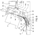
- a controller section (not shown) activates a plunger 104 so that the armature of the plunger 104 moves in the direction of an arrow A as shown in Fig. 6.
- the rollers 20 are separated from the rollers 19 via levers 105 and 106.
- a spring 107 pushes a pin 37a of the open/close lever 37.
- the open/close lever 37 rotates about the shaft 32a in the direction of an arrow C, and the rollers 23 are brought into pressure contact with the rollers 24 with the slip 200 being pinched therebetween. In other words, the rollers 23 are pushed against the rollers 24 by the resilient force of the spring 107.
- the stopper 101 rotates against the spring force of the spring 103 in association with the motion of the open/close lever 37 in the direction of the arrow C, and thus the tip section 101a of stopper 101 is lowered below the lower guide member 25.
- the rollers 23, 24 are driven to transfer the slip 200 toward the ink jet head 4a.
- the rotation of the drive pulley 32 mounted on the shaft 32a is transferred through the belt 33 to the pulley 34 mounted on the same shaft as the rollers 23 so that the rollers 23 are rotated.
- the tension of the belt 33 is adjustable by finely adjusting the position of an adjusting pulley 37b that is mounted on the open/close lever 37.
- the tension of the belt 33 is factory-adjusted to an appropriate level.
- the slip 200 As the slip 200 is advanced by the rotation of the rollers 23, 24, it is introduced between the intermediate rollers 21 and 22.
- the rollers 21 and 22 are always in pressure contact with each other.
- Rotational force of a drive motor (not shown) is transferred through the drive shaft 32a and the gears 35 and 36 to the rollers 21.
- the slip 200 that is transferred by the rollers 21, 22, 23 and 24, is introduced between the guide member 39 and the ink jet head 4a and printed.
- the ink jet head 4a is moved along the guide rail 7 to print one line of characters.
- the rollers are driven to move the slip 200 by a predetermined amount (for printing the next line), and then printing is performed by the ink jet head 4a again. These operation steps are repeated.
- the slip 200 After passing the printing area between the guide member 39 and the ink jet head 4a, the slip 200 enters an open space between the rollers 19 and 20.
- the distance from the position at which the slip 200 abuts the tip section 101a of the stopper 101 to the position at which the slip 200 reaches the open space between the rollers 19 and 20 is known and a corresponding feeding amount is pre-set in the controller section that controls the motor for driving these transfer rollers.
- the slip 200 reaches the space between the rollers 19 and 20.
- the plunger 104 is activated so that the armature moves in the direction of an arrow B, as shown in Fig. 5, to move the levers 105 and 106.
- the rollers 20 are brought into pressure contact with the rollers 19 and the leading end of the slip 200 is pinched by the rollers 19 and 20. Accordingly, the slip 200 can be transferred by the rollers 19 and 20.
- the pressure force acting between the rollers 19 and 20 is determined by the spring 108.
- the spring 107 is released from the pin 37a of the lever 37, and the resilient force of the spring 107 that acts to bring the rollers 23 in pressure contact with the rollers 24 is removed.
- the open/close lever 37 rotates about the shaft 32a in the direction of an arrow D due to the weight of the rollers 23.
- the slip is transferred by the rollers 23 and 24 immediately after it is inserted.
- the slip is transferred by the two sets of the rollers 23, 24, 21 and 22.
- the slip is transferred by the two sets of rollers 20, 19, 21 and 22.
- the slip is transferred only by the rollers 19 and 20.
- Validation printing by a printer in accordance with the present invention is performed in the following manner. While the rollers 19 and 20 are separated, a check 500 is inserted through the discharge opening 18 down to an area adjacent the rollers 21 and 22. After setting the check in position (described in more detail below), the plunger 104 is activated by a corresponding command or key operation to bring the rollers 19 and 20 in pressure contact with each other. After the rollers 19 and 20 pinch the check, the ink jet head 4a is operated to print on the check, and the rollers 19 are driven as required so that the check is transferred back toward the discharge opening while it is being printed.
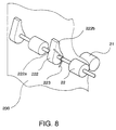
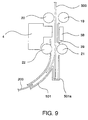
- Figs. 7 and 8 show perspective views of an area adjacent the intermediate rollers 21, 22.
- Fig. 7 shows a state where a check 500 for validation printing is inserted
- Fig. 8 shows a state where a slip 200 for slip printing is inserted.
- a plurality of stoppers 222 are pivotally mounted on the same shaft that mounts the intermediate rollers 22.
- Each of the stoppers 222 is biased by relatively weak spring force of a spring 223 (a torsion spring in this embodiment) into a stopping position in which a protrusion 222b extends through a window 251 that is defined in the paper guide, into the paper feed path (the contact between the lower window edge and the lower face of the protrusion defines the stopping position).
- the stoppers 222 rotate in a direction in which the paper feed path is opened. By this operation, the slip 200 can be transferred further upward.
- the stoppers 222 are provided on the same shaft as the roller 21 or 22.
- the paper feed path for cut-sheet paper between the insertion opening 27 and the discharge opening 18 comprises a first curved section and a second straight or substantially straight section.
- the curved section extends from the insertion opening up to the intermediate rollers 21, 22 and the straight section extends from the intermediate rollers to the discharge opening 18.
- the straight section is used in common for slips 220 and checks 500 and includes the printing area. Therefore, thin and weak paper can be as easily inserted as a check as can thick and strong paper.
- the stoppers 220 which define the lowermost position of the lower (leading) end of a check inserted through the discharge opening 18, extend into the straight section of the paper feed path just above the intermediate rollers 21, 22. Because of this structure a check can be easily positioned and, different from the structure shown in Fig. 9, there is no danger that a check, even if its leading end is curved or bent, unintentionally enters a wrong paper feed path.
- the plunger is a self-holding type plunger that performs pulling or pushing of its armature by an electrical current applied for only a short period of time. As a result, power consumption by the printer is lowered.
- the rollers 23 and 24 are kept open and the rollers 19 and 20 are kept closed.
- the rollers 19 and 20 are closed, and therefore a check for validation printing cannot be inserted to the printing area.
- the tip section 101a of the stopper 101 protrudes in the paper feed path.
- a slip for slip printing can also not be inserted into the printing area.
- the insertion opening 27 and the discharge opening 18 of the paper feed path for cut-sheet paper and the printing area are closed. Therefore, cut-sheet paper cannot be inserted by mistake while printing on roll paper.
- the plunger is operated by a respective command or key operation to separate the rollers 19 and 20 from each other or bring the rollers 19 and 20 into pressure contact with each other.
- the printing area and a part of the paper feed path for slip printing are also used for validation printing in which a check is inserted through the discharge opening that is used for discharging both slips and checks.
- the structure can accommodate a variety of different modes of usage and different types of paper. Also, during a specified print mode, a sheet of paper for a different print mode cannot be inserted by mistake.
- the description is made with reference to a printer that incorporates an ink jet head.
- the present invention is not limited to this particular embodiment, and the present invention is also applicable to a printer having any one of various types of print head, such as a dot impact type print head and the like.
- the present invention is not limited to a printer for printing bills or bank checks, but is also applicable to other types of printers.
- the reference to slips and checks in the foregoing description was only for the purpose of convenience and by no means intended to be restrictive. Both slip and check are representative for any kind of cut-sheet paper to which slip printing or validation printing may be applied.
Landscapes
- Handling Of Cut Paper (AREA)
- Handling Of Sheets (AREA)
- Delivering By Means Of Belts And Rollers (AREA)
Abstract
Description
- The present invention relates to a printer capable of printing on cut-sheet paper and, more particularly, to a point of sale (POS) printer for printing on cut-sheet paper, such as paper slips, bank checks etc..
- Printers that can print on cut-sheet paper, i.e., single sheets of paper, such as a paper voucher, a slip, a bank check or the like, are known. In these printers, a sheet of paper is transferred to a printing area by a first pair of transfer rollers disposed adjacent a paper insertion opening (referred to as insertion rollers hereinafter). The sheet of paper is printed at a printing area and then discharged out of the printer by a second pair of transfer rollers disposed adjacent a paper discharge opening (referred to as discharge rollers hereinafter). For inserting a sheet of paper, the rollers are separated from each other to facilitate the insertion of the paper.
- When printing on relatively large sheet of paper, such as a slip (herein after referred to as slip printing), the paper is inserted through the insertion opening, passed through a paper feed path past the printing area, and discharged through the discharge opening. On the other hand, when printing a few lines in a predetermined area on card-like cut-sheet paper such as a bank check for payment validation (herein after referred to as validation printing), the paper is inserted through the discharge opening and printing is performed while the paper is transferred back toward the discharge opening past the printing area. For the sake of convenience, the term "slip" will be used hereinafter as representative for any kind of cut-sheet paper suitable for slip printing and the term "check" will be used as representative for any kind of cut-sheet paper suitable for validation printing.
- For example, Fig. 9 shows an explanatory view of a conventional printer that is capable of both slip printing and validation printing.
Reference numeral 4 denotes a print head for printing on aslip 200 or acheck 500 that is transferred to the printing area betweenprint head 4 and aplaten 38 by a pair ofdischarge rollers intermediate rollers Reference numeral 501 denotes a paper feed path for transferring aslip 200. Aslip 200 inserted through an insertion opening on the front side of the printer into thepaper feed path 501, it is guided by apaper guide 39 to the printing area, printed by theprint head 4 and discharged through a discharge opening on the top. Note that a pair of insertion rollers (not shown) for slips is provided next to the insertion opening. For printing on thecheck 500, thedischarge rollers intermediate rollers check 500 is inserted through the discharge opening down into agroove section 501a. Then, thedischarge rollers intermediate rollers check 500, and printing by theprint head 4 is performed as the check is advanced upwardly back to the discharge opening. - The above-described printer suffers the following problems.
- (a) In order to insert a slip for slip printing, the insertion rollers are preferably separated from each other while the
discharge rollers intermediate rollers check 500. - (b) In the POS printer of this type, a slip or check must be inserted into the appropriate opening. As a result, there is the danger that a slip or check is inserted into the wrong opening by mistake. There is another type of POS printer that prints on roll paper for printing receipts in addition to printing on cut-sheet paper. In this type of POS printer, a portion of the paper feed path is used in common for cut-sheet paper and roll paper, and each type of paper is transferred to same printing area. In this case, the paper feed path is formed in a manner that each type of paper is discharged through a different discharge opening. As a consequence, the number of openings for inserting and discharging paper is increased, and the danger of misoperation or misinsertion is even higher.
- EP-B-0 428 163 discloses an impact dot matrix POS printer according to the precharacterizing part of
claim 1, which differs from the one explained above with reference to Fig. 9 in that only the insertion rollers and the intermediate rollers but not the discharge rollers are provided. The platen and one of the intermediate rollers are supported on a first lever and one of the insertion rollers is supported on a second lever. The first lever is pivotally supported to close or open the intermediate rollers. When the intermediate rollers are open the printing area is also open, i.e., the platen is retracted from it working position opposite the print head. The second lever is also pivotally supported to close or open the insertion rollers. A first plunger is used to drive the first lever and a second plunger is used to drive the second lever. Both plungers are controlled in such a way that the insertion rollers and the intermediate rollers are either both open or both closed. - EP-A-0 676 295 discloses a similar printer having a pair of discharge rollers and a pair of intermediate rollers. Regarding the intermediate rollers, the structure is the same as that disclosed in the document EP-B-0 428 163. One of the discharge rollers is mounted on a second lever which in turn is pivotally mounted on the first lever supporting one of the intermediate rollers. When the first lever is driven by a plunger to open the intermediate rollers, the second lever is turned at the same time to open the discharge rollers. Thus, both the discharge rollers and the intermediate rollers can be driven together to be both open or both closed.
- The present invention is made to solve the above-described problems of the prior art. It is an object of the present invention to provide a printer capable of printing on a variety of types of cut-sheet paper in which a comparatively simple mechanism is used for opening/closing of transfer rollers and in which insertion of cut-sheet paper is facilitated and erroneous insertion prevented.
- This object is achieved with a printer as claimed in
claim 1. Preferred embodiments of the invention are subject-matter of the dependent claims. - In accordance with the claimed solution, when performing slip printing, only the rollers of the first set at the insertion side are separated from each other so that a slip for slip printing can be inserted. At this moment, the rollers of the second set disposed adjacent the discharge opening which is used for both discharging a slip for slip printing and inserting/discharging a check for validation printing, are maintained in a closed state. Thus, a check for validation printing cannot be inserted by mistake. On the other hand, when performing validation printing, the rollers of the first set are closed and those of the second set are separated from each other. Thus, a slip for slip printing cannot be inserted by mistake.
- Preferred embodiments of the invention will be explained below in detail with reference to the drawings, in which
- Fig. 1
- schematically shows a cross-sectional view of the internal structure of a printer in accordance with one embodiment of the present invention,
- Fig. 2
- shows a front perspective view of the of the printer with a front cover removed,
- Fig. 3
- shows a perspective view of a paper transfer section of the printer,
- Fig. 4
- shows a perspective view of a roller drive mechanism of the printer,
- Fig. 5
- shows a side view of the transfer system in one state,
- Fig. 6
- shows a side view of a transfer system in another state,
- Fig. 7
- shows a perspective view of a stopper in a one state,
- Fig. 8
- shows a perspective view of the stopper in another state, and
- Fig. 9
- shows a side view of a conventional structure for positioning a sheet for validation printing.
- Figs. 1 and 2 show the overall structure of a
printer 1 in accordance with one embodiment of the present invention. As shown in Fig. 1, theprinter 1 has amain case 2 made of, for example, resin or the like. A roll S of paper is disposed in a rear part inside themain case 2. Apaper transfer section 3 for transferring paper to be printed is mounted in a front part of thecase 2. An inkjet printing section 4 for printing on the paper is disposed in front of thepaper transfer section 3. Theprinting section 4 is covered by afront cover 5 made of resin or the like. The paper roll S, thepaper transfer section 3 and theprinting section 4 are mounted on amain frame 6 made of metal or the like. As shown in Fig. 2, theprinting section 4 is capable of moving between the lateral sides of themain frame 6 along aguide rail 7 fixed to themain frame 6. - As shown in Fig. 1, an
ink jet head 4a of theprinting section 4 is disposed opposite aplaten section 8 that is provided in thepaper transfer section 3. A printing area is defined between theink jet head 4a and theplaten section 8. The paper roll S is rotatably supported on a pair ofsupport rollers roll core 9. The outer end of the paper roll S is drawn from the lower side of the printer toward the upper side. A paper path for the roll paper from paper roll S is formed in thepaper transfer section 3. In other words, the roll paper is guided and transferred by apaper guide 12 and aroller 13 to theplaten section 8. After printing on the roll paper by theprinting section 4, the roll paper is further transferred by aroller 14 and discharged through adischarge opening 16 defined in anupper cover 15. When cut-sheet paper (described below) is not inserted, the roll paper can be printed. - As shown in Fig. 1, the
upper cover 15 is rotatably mounted about apivot axis 17. In order to facilitate insertion of the roll paper, theplaten section 8 is designed to move closer to and farther from theink jet head 4a in association with the opening or closing of theupper cover 15. In other words, theplaten section 8 and transferroller 14 are supported on a frame which is rotatable about a shaft of theroller 13. This frame is connected to alever 46 and is forced by a spring mounted on thelever 46 in a direction in which theplaten section 8 and theroller 14 are moved away from theink jet head 4a. With this mechanism, when theupper cover 15 is closed, apressure lever 47 fixed to the interior of theupper cover 15 pushes an upper section of thelever 46, and theplaten section 8 is moved closer to theink jet head 4a into a position where printing can be performed. On the other hand, when theupper cover 15 is opened for setting the roll paper, the pressure of thepressure lever 47 is released from thelever 46. As a result, theplaten section 8 is moved away from theink jet head 4a by the resilient force of the spring mounted on thelever 46 and is placed in a receded position. Consequently, the roll paper is smoothly guided past the printing section to thedischarge opening 16. - The
upper cover 15 and thefront cover 5 define adischarge opening 18 in the upper central area of the printer for discharging cut-sheet paper (aslip 200 on which slip printing is performed or acheck 500 on which validation printing is performed). As described below, thedischarge opening 18 also serves as an insertion opening for validation printing. A set ofdischarge rollers discharge opening 18. A set ofintermediate rollers printing section 4, and a set ofinsertion rollers printing section 4. These rollers and a pair ofguide members slip 200. As shown in Fig. 2, when slip printing is performed, aslip 200 is inserted into apaper insertion opening 27. - Figs. 3 and 4 show the
paper transfer section 3 in accordance with one embodiment of the present invention. - As shown in these figures each of the above mentioned sets of rollers in this embodiment comprises two pairs of rollers, each pair including a drive roller coupled to a drive source and an associated pinch roller. The two drive rollers of a respective set are fixed to the same shaft and the two pinch rollers have the same rotary axis. It is to be noted that the number of pairs of drive and pinch rollers in the respective sets of rollers is not critical to the invention.
- As shown in Figs. 3 and 4, the
rollers metal support frame 28 substantially U-shaped in cross-section. Thesupport frame 28 is mounted on ametal transfer frame 29 that forms a paper feed path for cut-sheet paper. Theroller 13 for transferring roll paper is formed from a material that is not slippery, such as rubber or the like, and has adrive shaft 30 coupled to a drive motor (not shown). Theroller 13 and theroller 14 are rotated in the same direction by a gear train (not shown). Thesupport frame 28 is pivotally mounted about thedrive shaft 30 of theroller 13. - As shown in Fig. 3,
insertion rollers 23 for transferring aslip 200 are mounted on ashaft 31 that is rotatably mounted on an open/close lever 37. Also,intermediate rollers 21 are mounted on ashaft 100 that is rotatably mounted on thetransfer frame 29. - As shown in Fig. 4, the
insertion rollers 23 are driven by adrive pulley 32 that is driven by a motor (not shown), abelt 33 and apulley 34. Theintermediate rollers 21 are driven by agear 35 that is driven by the above-described motor via agear 36 that engages thegear 35. The open/close lever 37 is pivotally mounted on thetransfer frame 29 about ashaft 32a having the drivepulley 32 mounted on one end thereof and thegear 35 on the other end. - Referring to Figs. 5 and 6, a cut-sheet transfer mechanism and its operation in the case of slip printing will be described. It is noted that the roll paper transfer mechanism shown in Fig. 1 is not shown in Figs. 5 and 6.
- The
paper insertion opening 27 is defined by the upper andlower guide members slip 200. When theslip 200 is inserted, therollers 23 are separated from therollers 24 and do not obstruct insertion of theslip 200. At this moment, atip section 101a of astopper 101 protrudes from thelower guide member 25 into the paper feed path by the resilient force of aspring 103. When theslip 200 is inserted, its leading end is stopped at a position corresponding to that of thestopper 101. Apaper detector 102 is provided generally at the same location as thetip section 101a of thestopper 101. Thepaper detector 102 detects insertion of theslip 200. - The
detector 102 also detects the trailing end of theslip 200. Therefore, thedetector 102 can be used, for example, to control the bottom margin on a slip (the position of the last printing line) that is pre-set prior to printing. As shown in Fig. 5, when therollers 23 are separated from therollers 24, therollers 20 contact therollers 19 under pressure. Therefore, aslip 200 cannot be inserted through thedischarge opening 18 by mistake. - When the
slip 200 stops at thestopper 101, and the paper detector detects that the slip is set in position, a controller section (not shown) activates aplunger 104 so that the armature of theplunger 104 moves in the direction of an arrow A as shown in Fig. 6. By this operation, therollers 20 are separated from therollers 19 vialevers spring 107 pushes apin 37a of the open/close lever 37. As a result, the open/close lever 37 rotates about theshaft 32a in the direction of an arrow C, and therollers 23 are brought into pressure contact with therollers 24 with theslip 200 being pinched therebetween. In other words, therollers 23 are pushed against therollers 24 by the resilient force of thespring 107. - At this moment, the
stopper 101 rotates against the spring force of thespring 103 in association with the motion of the open/close lever 37 in the direction of the arrow C, and thus thetip section 101a ofstopper 101 is lowered below thelower guide member 25. - Then, the
rollers slip 200 toward theink jet head 4a. The rotation of thedrive pulley 32 mounted on theshaft 32a is transferred through thebelt 33 to thepulley 34 mounted on the same shaft as therollers 23 so that therollers 23 are rotated. The tension of thebelt 33 is adjustable by finely adjusting the position of an adjustingpulley 37b that is mounted on the open/close lever 37. The tension of thebelt 33 is factory-adjusted to an appropriate level. - As the
slip 200 is advanced by the rotation of therollers intermediate rollers rollers drive shaft 32a and thegears rollers 21. Theslip 200, that is transferred by therollers guide member 39 and theink jet head 4a and printed. In a preferred embodiment, while the unshown drive motor for driving the rollers is stopped, theink jet head 4a is moved along theguide rail 7 to print one line of characters. Then, the rollers are driven to move theslip 200 by a predetermined amount (for printing the next line), and then printing is performed by theink jet head 4a again. These operation steps are repeated. - After passing the printing area between the
guide member 39 and theink jet head 4a, theslip 200 enters an open space between therollers slip 200 abuts thetip section 101a of thestopper 101 to the position at which theslip 200 reaches the open space between therollers slip 200 has been transferred by the pre-set feeding amount, theslip 200 reaches the space between therollers - At this moment, the
plunger 104 is activated so that the armature moves in the direction of an arrow B, as shown in Fig. 5, to move thelevers rollers 20 are brought into pressure contact with therollers 19 and the leading end of theslip 200 is pinched by therollers slip 200 can be transferred by therollers rollers spring 108. When the armature of theplunger 104 moves in the direction of the arrow B, an abuttingsection 105a of thelever 105 pushes up thespring 107. As a result, thespring 107 is released from thepin 37a of thelever 37, and the resilient force of thespring 107 that acts to bring therollers 23 in pressure contact with therollers 24 is removed. The open/close lever 37 rotates about theshaft 32a in the direction of an arrow D due to the weight of therollers 23. - As a result, the pressure contact between the
rollers 23 androllers 24 is released, and therollers 23 are separated from therollers 24. In this state, the slip is transferred by the rotation of the two sets of therollers spring 103 forces thetip section 101a of thestopper 101 to protrude above thelower guide member 25 into the paper feed path. However, since the spring force of thespring 103 is set to be very weak, thetip section 101a cannot push up theslip 200 and does not prevent it from being advanced. - As described above, when slip printing is performed on a
slip 200, the slip is transferred by therollers rollers rollers rollers rollers rollers rollers rollers rollers rollers rollers - Next, a transfer mechanism and an operation for transferring a check for validation printing will be described in detail. Validation printing by a printer in accordance with the present invention is performed in the following manner. While the
rollers check 500 is inserted through thedischarge opening 18 down to an area adjacent therollers plunger 104 is activated by a corresponding command or key operation to bring therollers rollers ink jet head 4a is operated to print on the check, and therollers 19 are driven as required so that the check is transferred back toward the discharge opening while it is being printed. - In this manner, when a check can be inserted for validation printing, the
rollers insertion opening 27 by mistake. - Figs. 7 and 8 show perspective views of an area adjacent the
intermediate rollers check 500 for validation printing is inserted, and Fig. 8 shows a state where aslip 200 for slip printing is inserted. - A plurality of
stoppers 222 are pivotally mounted on the same shaft that mounts theintermediate rollers 22. Each of thestoppers 222 is biased by relatively weak spring force of a spring 223 (a torsion spring in this embodiment) into a stopping position in which aprotrusion 222b extends through awindow 251 that is defined in the paper guide, into the paper feed path (the contact between the lower window edge and the lower face of the protrusion defines the stopping position).. - When a
check 500 for validation printing is inserted through thedischarge opening 18 while therollers check 500 abuts against theupper surface 222a of theprotrusions 222b of thestoppers 222 so that thecheck 500 is set in position, as shown in Fig. 7. At this moment, the leading end of thecheck 500 does not contact therollers plunger 104 is activated to bring therollers rollers check 500 is printed. - On the other hand, as shown in Fig. 8, when a
slip 200 for slip printing is fed, its leading end passes therollers protrusion 222b of thestoppers 222. As a result, thestoppers 222 rotate in a direction in which the paper feed path is opened. By this operation, theslip 200 can be transferred further upward. In accordance with an embodiment of the present invention, thestoppers 222 are provided on the same shaft as theroller slip 200 is pinched by therollers stoppers 222 and has to withstand the reaction force imparted by the stoppers to the slip edge as the stoppers are moved to free the paper feed path for passage of the slip. As a result, even a very weak slip (i.e. paper of relatively low stiffness) can be readily transferred, and slips for slip printing are transferred free of troubles. - As shown in the figures, the paper feed path for cut-sheet paper between the
insertion opening 27 and thedischarge opening 18 comprises a first curved section and a second straight or substantially straight section. The curved section extends from the insertion opening up to theintermediate rollers discharge opening 18. The straight section is used in common for slips 220 andchecks 500 and includes the printing area. Therefore, thin and weak paper can be as easily inserted as a check as can thick and strong paper. Furthermore, in the preferred embodiment described above, the stoppers 220 which define the lowermost position of the lower (leading) end of a check inserted through thedischarge opening 18, extend into the straight section of the paper feed path just above theintermediate rollers - In a preferred embodiment, the plunger is a self-holding type plunger that performs pulling or pushing of its armature by an electrical current applied for only a short period of time. As a result, power consumption by the printer is lowered.
- Preferably, when the roll paper from paper roll S is printed, the
rollers rollers rollers rollers tip section 101a of thestopper 101 protrudes in the paper feed path. As a consequence, a slip for slip printing can also not be inserted into the printing area. In this manner, when printing on the roll paper, theinsertion opening 27 and the discharge opening 18 of the paper feed path for cut-sheet paper and the printing area are closed. Therefore, cut-sheet paper cannot be inserted by mistake while printing on roll paper. - In the structure in accordance with an embodiment of the present invention, the plunger is operated by a respective command or key operation to separate the
rollers rollers - It should be noted that the present invention is not limited to the embodiment described above, and a variety of modifications may be implemented.
- For example, in the above-described embodiment, the description is made with reference to a printer that incorporates an ink jet head. However, the present invention is not limited to this particular embodiment, and the present invention is also applicable to a printer having any one of various types of print head, such as a dot impact type print head and the like.
- Furthermore, the present invention is not limited to a printer for printing bills or bank checks, but is also applicable to other types of printers. Also, as mentioned previously, the reference to slips and checks in the foregoing description was only for the purpose of convenience and by no means intended to be restrictive. Both slip and check are representative for any kind of cut-sheet paper to which slip printing or validation printing may be applied.
Claims (13)
- A printer for printing on cut-sheet paper comprising:a first insertion opening (27) for inserting cut-sheet paper (200),a combined discharge/insertion opening (18) for inserting and discharging cut-sheet paper (200, 500),a paper feed path connecting said insertion opening (27) and said discharge/insertion opening (18),a printing area (4a, 8) provided in said paper feed path for printing on cut-sheet paper (200, 500) inserted into said paper feed path through said insertion opening (27) or said discharge/insertion opening (18),a first set of rollers (23, 24) disposed in said paper feed path at the insertion opening side thereof, the first set of rollers comprising at least one first pair of a drive roller (23) and a pinch roller (24),a first open/close mechanism (37) for setting said first set of rollers (23, 24) into either an open state in which the drive roller and the pinch roller of said at least one first pair are separated from each other to allow insertion of cut-sheet paper (200) in between, or a closed state in which the rollers engage the cut-sheet paper for transporting it along said paper feed path toward said printing area,a second set of rollers (19, 20) disposed in said paper feed path at the discharge opening side thereof, the second set of rollers comprising at least one second pair of a drive roller and a pinch roller, anda second open/close mechanism (105, 106) for setting the said second set of rollers (19, 20) into either an open state in which the drive roller and the pinch roller of said at least one second pair are separated from each other to allow insertion of cut-sheet paper (200, 500) in between, or a closed state in which the rollers engage the cut-sheet paper for transporting it past said printing area toward said discharge opening (18),
characterized bymeans (37a, 107, 105a) for coupling said first and second open/close mechanisms such that when one set of rollers is in its open state the other is in its closed state, andsingle drive means (104) for operating said first and second open/close mechanisms. - The printer according to claim 1, wherein said paper feed path is divided at a position between said insertion opening (27) and said discharge/insertion opening (18) into a first substantially straight section on the discharge/insertion opening side and a second curved section on the insertion opening side, the printing area (4a, 8) being in the first section.
- The printer according to claim 1 or 2, further having and stopper means (222, 22a, 222b) for positioning the leading end of cut-sheet paper (500) inserted through said discharge/insertion opening (18), said stopper means being arranged to allow passage of cut-sheet paper (200) through the paper feed path in a first direction from the insertion opening (27) toward the discharge/insertion opening (18) but to prevent passage of cut-sheet paper (500) in a second direction opposite to the first direction.
- The printer according to claims 2 and 3, wherein said stopper means (222, 22a, 222b) is positioned at or near said position at which the paper feed path is divided into said first and second sections.
- The printer according to any one of the preceding claims, further comprising a third set of rollers (21, 22) for transporting cut-sheet paper (200), the third set being disposed intermediate the said first set and said printing area (4a, 8).
- The printer according to claim 5 as dependent on claim 3, wherein said third set of rollers (21, 22) is always in a closed state and said stopper means (222, 222b) is positioning between said third set of rollers (21, 22) and said printing area (4a, 8).
- The printer according to claim 6, wherein said stopper means (222) is provided immediately next to said third set of rollers (21, 22).
- The printer according to claim 7, wherein said stopper means comprises one or more stopper members (222) supported on an axis coaxial with a rotary axis of either drive or pinch rollers of said third set of rollers (21, 22) so as to be turnable between a first and a second position, and biasing means (223) for biasing the one or more stopper members into said first position, each stopper member (222) having a protrusion (222b) extending into the paper feed path in said first position and having an abutment face (22a) for abutment by cut-sheet paper (500) inserted in said second direction, and retracted in said second position so as to allow passage of cut-sheet paper (200) in said first direction, said stopper members and biasing means being arranged such that the stopper members are turnable toward said second position by cut-sheet paper advanced by said third set of rollers (21, 22) in said first direction.
- The printer according to any one of the preceding claims, further comprisinga stopper (101, 101a) for positioning the leading end of cut-sheet paper (200) inserted through said insertion opening (27), andmoving means (37, 103) moving the stopper between a first position in which it projects into said paper feed path and a second position in which it is retracted from the paper feed path, said moving means being coupled to said first open/close mechanism (37) so as to be operated by said single drive means (104) in association with said first open/close mechanism such that the stopper is in its first position when said first set of rollers (23, 24) is in its open state.
- The printer according to any one of the preceding claims, further comprising a paper feed path for transferring a roll paper past said printing area (4a, 8).
- The printer according to claim 10, further comprising means for keeping said first set of rollers (23, 24) in its open state and said second set of rollers (19, 20) in its closed state for printing on roll paper.
- The printer according to any one of the preceding claims, wherein of one of said first and second sets of rollers (23, 24, 19, 20) the or each pinch roller (24) is supported by a frame (29) and the or each drive roller (23) is fixed on a shaft (31) rotatably supported by a lever (37) which is in turn pivotally mounted about a pivot axis (32a) on said frame (29), said lever forming the respective open/close mechanism, and wherein a driving force for rotating said drive roller (23) is applied through a belt (33) stretched between a driven pulley (34) fixed on said shaft (31) and drive pulley (32) disposed coaxially with said pivot axis (32a).
- The printer according to claim 12, further comprising an adjusting pulley (37b) provided on said lever (37) for adjusting the tension of the belt (33).
Applications Claiming Priority (6)
| Application Number | Priority Date | Filing Date | Title |
|---|---|---|---|
| JP12066496A JP3520383B2 (en) | 1996-05-15 | 1996-05-15 | Printer |
| JP8120665A JPH09300757A (en) | 1996-05-15 | 1996-05-15 | Printer |
| JP12066496 | 1996-05-15 | ||
| JP120664/96 | 1996-05-15 | ||
| JP12066596 | 1996-05-15 | ||
| JP120665/96 | 1996-05-15 |
Publications (3)
| Publication Number | Publication Date |
|---|---|
| EP0807523A2 true EP0807523A2 (en) | 1997-11-19 |
| EP0807523A3 EP0807523A3 (en) | 1998-09-09 |
| EP0807523B1 EP0807523B1 (en) | 2001-10-10 |
Family
ID=26458196
Family Applications (1)
| Application Number | Title | Priority Date | Filing Date |
|---|---|---|---|
| EP19970107925 Expired - Lifetime EP0807523B1 (en) | 1996-05-15 | 1997-05-15 | Printer |
Country Status (2)
| Country | Link |
|---|---|
| EP (1) | EP0807523B1 (en) |
| DE (1) | DE69707194T2 (en) |
Cited By (1)
| Publication number | Priority date | Publication date | Assignee | Title |
|---|---|---|---|---|
| US8243905B2 (en) | 2005-04-28 | 2012-08-14 | Apple Inc. | Multi-participant conference setup |
Family Cites Families (1)
| Publication number | Priority date | Publication date | Assignee | Title |
|---|---|---|---|---|
| JP2780402B2 (en) * | 1989-04-10 | 1998-07-30 | セイコーエプソン株式会社 | Micro paper feed mechanism of printer |
-
1997
- 1997-05-15 EP EP19970107925 patent/EP0807523B1/en not_active Expired - Lifetime
- 1997-05-15 DE DE1997607194 patent/DE69707194T2/en not_active Expired - Lifetime
Cited By (1)
| Publication number | Priority date | Publication date | Assignee | Title |
|---|---|---|---|---|
| US8243905B2 (en) | 2005-04-28 | 2012-08-14 | Apple Inc. | Multi-participant conference setup |
Also Published As
| Publication number | Publication date |
|---|---|
| EP0807523A3 (en) | 1998-09-09 |
| DE69707194D1 (en) | 2001-11-15 |
| DE69707194T2 (en) | 2002-06-06 |
| EP0807523B1 (en) | 2001-10-10 |
Similar Documents
| Publication | Publication Date | Title |
|---|---|---|
| US5895158A (en) | Printer with an improved feeding system | |
| US6439454B1 (en) | Transaction printer | |
| US6602008B2 (en) | Print-medium transport unit | |
| JP2697276B2 (en) | Printer | |
| US5524994A (en) | Paper skew removal apparatus and a printer using the same | |
| US5328281A (en) | Recording medium feed mechanism for a printer and method of medium feed control | |
| EP1219554B1 (en) | Document feeder of printer | |
| EP0427290A2 (en) | Printer accomodating two types of printing sheet | |
| JP3711677B2 (en) | Printer | |
| JP4370730B2 (en) | Printing paper transport apparatus, control method thereof, and program | |
| HK1006443B (en) | Printer accomodating two types of printing sheet | |
| EP0807523B1 (en) | Printer | |
| EP0807527B1 (en) | Printer | |
| JP3520383B2 (en) | Printer | |
| US8550734B2 (en) | Transportation guide mechanism and recording device having the same | |
| KR100529813B1 (en) | Printer device, its control method and information recording medium | |
| JP3600273B2 (en) | Sheet introduction device | |
| JPH09300757A (en) | Printer | |
| JPH06183084A (en) | Paper feeding mechanism of printer | |
| JP2002003011A (en) | Printer paper ejection device, control method thereof, and information recording medium | |
| JPH092701A (en) | Paper clamp device | |
| JPH10120199A (en) | Sheet feeding device and sheet processing device provided with the sheet feeding device | |
| JPH0636849U (en) | Printer bail arm mechanism | |
| JPS6236255A (en) | Sheet-head adjustment for printing device | |
| JPH11147340A (en) | Printer device, control method therefor, and information recording medium |
Legal Events
| Date | Code | Title | Description |
|---|---|---|---|
| PUAI | Public reference made under article 153(3) epc to a published international application that has entered the european phase |
Free format text: ORIGINAL CODE: 0009012 |
|
| AK | Designated contracting states |
Kind code of ref document: A2 Designated state(s): DE FR GB IT |
|
| PUAL | Search report despatched |
Free format text: ORIGINAL CODE: 0009013 |
|
| AK | Designated contracting states |
Kind code of ref document: A3 Designated state(s): DE FR GB IT |
|
| 17P | Request for examination filed |
Effective date: 19990302 |
|
| GRAG | Despatch of communication of intention to grant |
Free format text: ORIGINAL CODE: EPIDOS AGRA |
|
| 17Q | First examination report despatched |
Effective date: 20001122 |
|
| GRAG | Despatch of communication of intention to grant |
Free format text: ORIGINAL CODE: EPIDOS AGRA |
|
| GRAH | Despatch of communication of intention to grant a patent |
Free format text: ORIGINAL CODE: EPIDOS IGRA |
|
| GRAH | Despatch of communication of intention to grant a patent |
Free format text: ORIGINAL CODE: EPIDOS IGRA |
|
| GRAA | (expected) grant |
Free format text: ORIGINAL CODE: 0009210 |
|
| AK | Designated contracting states |
Kind code of ref document: B1 Designated state(s): DE FR GB IT |
|
| REF | Corresponds to: |
Ref document number: 69707194 Country of ref document: DE Date of ref document: 20011115 |
|
| REG | Reference to a national code |
Ref country code: GB Ref legal event code: IF02 |
|
| ET | Fr: translation filed | ||
| PLBE | No opposition filed within time limit |
Free format text: ORIGINAL CODE: 0009261 |
|
| STAA | Information on the status of an ep patent application or granted ep patent |
Free format text: STATUS: NO OPPOSITION FILED WITHIN TIME LIMIT |
|
| 26N | No opposition filed | ||
| PGFP | Annual fee paid to national office [announced via postgrant information from national office to epo] |
Ref country code: DE Payment date: 20130515 Year of fee payment: 17 Ref country code: GB Payment date: 20130515 Year of fee payment: 17 |
|
| PGFP | Annual fee paid to national office [announced via postgrant information from national office to epo] |
Ref country code: IT Payment date: 20130521 Year of fee payment: 17 Ref country code: FR Payment date: 20130531 Year of fee payment: 17 |
|
| REG | Reference to a national code |
Ref country code: DE Ref legal event code: R119 Ref document number: 69707194 Country of ref document: DE |
|
| GBPC | Gb: european patent ceased through non-payment of renewal fee |
Effective date: 20140515 |
|
| REG | Reference to a national code |
Ref country code: FR Ref legal event code: ST Effective date: 20150130 |
|
| REG | Reference to a national code |
Ref country code: DE Ref legal event code: R119 Ref document number: 69707194 Country of ref document: DE Effective date: 20141202 |
|
| PG25 | Lapsed in a contracting state [announced via postgrant information from national office to epo] |
Ref country code: IT Free format text: LAPSE BECAUSE OF NON-PAYMENT OF DUE FEES Effective date: 20140515 Ref country code: DE Free format text: LAPSE BECAUSE OF NON-PAYMENT OF DUE FEES Effective date: 20141202 |
|
| PG25 | Lapsed in a contracting state [announced via postgrant information from national office to epo] |
Ref country code: FR Free format text: LAPSE BECAUSE OF NON-PAYMENT OF DUE FEES Effective date: 20140602 Ref country code: GB Free format text: LAPSE BECAUSE OF NON-PAYMENT OF DUE FEES Effective date: 20140515 |