EP0807451A2 - Fixing plate for safety harness for guiding two crossing belts - Google Patents
Fixing plate for safety harness for guiding two crossing belts Download PDFInfo
- Publication number
- EP0807451A2 EP0807451A2 EP97104201A EP97104201A EP0807451A2 EP 0807451 A2 EP0807451 A2 EP 0807451A2 EP 97104201 A EP97104201 A EP 97104201A EP 97104201 A EP97104201 A EP 97104201A EP 0807451 A2 EP0807451 A2 EP 0807451A2
- Authority
- EP
- European Patent Office
- Prior art keywords
- belt
- overlap
- belts
- holding plate
- bushings
- Prior art date
- Legal status (The legal status is an assumption and is not a legal conclusion. Google has not performed a legal analysis and makes no representation as to the accuracy of the status listed.)
- Withdrawn
Links
Images

Classifications
-
- A—HUMAN NECESSITIES
- A62—LIFE-SAVING; FIRE-FIGHTING
- A62B—DEVICES, APPARATUS OR METHODS FOR LIFE-SAVING
- A62B35/00—Safety belts or body harnesses; Similar equipment for limiting displacement of the human body, especially in case of sudden changes of motion
- A62B35/0006—Harnesses; Accessories therefor
- A62B35/0025—Details and accessories
- A62B35/0031—Belt sorting accessories, e.g. devices keeping the belts in comfortable positions
Definitions
- the invention relates to a holding plate for a safety harness for guiding two intersecting belts.
- the holding plate has at least one slit-shaped overlap lead-through, through which both straps are passed, the straps crossing within the overlap lead-through.
- the holding plate additionally has a number of first slot-shaped belt bushings for the first belt and a number of second slot-shaped belt bushings for the second belt.
- the invention further relates to a safety harness with such a holding plate.
- Various belt guides are known for safety harnesses.
- they have an abdominal belt with fastenings on the front and a pair of back belts, which extend from the back and intersect at the shoulder blade height, and which are continued upward as shoulder belts and adjoining front belt regions.
- the front belt areas are brought together at the bottom as a seat belt, with leg straps extending from the central area thereof, which can be connected to the lower ends of the back belts. It is also possible to let the sloping seat belts continue to run upwards to a locking eye in the chest area. It is important that the force is distributed as evenly as possible on the back and buttocks when positioning the workstation.
- the holding plates are used in two or three versions for a safety harness, namely for fixing the two back belts and for fixing a front belt area crossing the waist belt, a shoulder-seat belt.
- the handling of these holding plates is made more difficult by the fact that it must always be ensured that none of the belts folds when pulled through the bushings.
- Such a holding plate is known from US-A-5,433,289 and DE-C-28 24 734.
- This holding plate has a belt feed-through for each of the first and second belts and an overlap feed-through, through which both belts are pulled: the overlap feed-through is a slot of uniform width.
- a holding plate with two slit-shaped belt bushings is known from EP-A-0 584 521. It is called a buckle there.
- the two straps cross within the buckle.
- the buckle moves relatively easily and there is also the risk that one of the straps folds in the longitudinal direction.
- Holding plates are also known from EP-A-0 508 278, DE-A-28 24 734 and DE-U-89 14 878. They serve to fix the crossing point of the back belts and thereby ensure that the safety harness is properly seated.
- the bushings have a uniform width.
- the invention has for its object to provide a holding plate for guiding two belts in their intersection, for example two back belts or the waist belt and the shoulder-seat belt.
- the holding plate is intended to fix the two belts in this area, largely eliminate the risk of the belts folding and be easy to handle.
- the holding plate has means for guiding the two belts such that at least one of the two belts only partially overlaps with the other belt within the overlap bushing and that the at least one overlapping bushing has a graduated slot width, wherein the larger slot width is in the area in which the first and the second belt partially overlap in the retracted state within the overlap passage.
- the means for guiding the two belts in such a way that at least one of the two belts is only partially overlapped by the other can consist in a corresponding arrangement of the first and second bushings mentioned at the beginning or in one or more further overlapping bushings within which both belts are completely or partially overlap.
- two overlap feedthroughs are provided in which the belts only partially overlap, the point of complete overlap being between the two overlap feedthroughs, and before and after the overlap feedthroughs is at least a first feedthrough only for the first belt and a second feedthrough only intended for the second belt.
- the outline of the overlap bushing is adapted to the combined cross-sectional profile of the belts which intersect in the retracted state at this point.
- the area of the larger slot width of the overlap bushing is preferably aligned with both the first bushings and the second bushings. This ensures that the straps do not kink laterally in the area of the holding plate.
- the overlap bushing or the overlap bushings is preferably arranged between two of the first and / or two of the second bushings.
- Such holding plates are used in particular for guiding an abdominal belt and a front belt region of a shoulder-seat belt of a safety harness crossing the abdominal belt.
- the waist belt is pulled through the first bushings and these are arranged next to each other along an approximately horizontal straight line.
- the front one The belt area is drawn through the second bushings, which are arranged along an oblique straight line.
- the first and the second bushings are each aligned approximately at right angles to the straight line along which they are arranged. For the first bushings, this means that they are aligned approximately vertically, while the second bushings have an orientation of approximately 45 ° to the vertical. In general, however, this only applies to the second bushings close to the seat, i.e. the second bushings below the overlapping bushings.
- the alignment of the second feedthroughs close to the chest depends on the intended course of the front belt area in the chest area. The closer the course of the vertical approaches, the more the breast-near passage is tilted into the horizontal. If several breast passages close to the chest are provided, the bushings are gradually tilted more. Preferably, a plurality of second passages close to the chest are provided, which are successively tilted more horizontally, the belt only being threaded up to the passage which gives it the desired course.
- Two overlap bushings are preferably provided. Like the first bushings, they are aligned vertically. Between the overlap feed-throughs, both belts are expediently guided on the outside, ie the side remote from the body, of the holding plate and at the same time through a holding eye, for example a D-shaped ring, which serves as an attachment point for a safety belt or holding belt. The two straps cross in the eyelet.
- the shoulder-seat belt is expediently in the overlap area directly against the holding plate or the eyelet, while the abdominal belt lies above it.
- the holding plate is preferably reinforced by a roof-like support, the ridge line of the roof-like reinforcement coinciding with the edge of the overlap feedthrough near the chest, so that this overlap feedthrough is located in the sloping surface of the roof-like reinforcement near the seat.
- This inclined surface merges into the plane of the holding plate approximately along the center line between the two overlap passages.
- the sloping surface of the roof-like reinforcement close to the chest extends to the subsequent first implementation.
- the roof-like reinforcement ensures that the retaining eyelet protrudes somewhat, thereby creating a connecting element, e.g. a snap hook that can be hooked in more easily.
- the roof-like reinforcement is attached to both sides of the holding plate so that it can be used on both the right and left side of the body.
- a safety harness generally has two such holding plates, namely in the area of intersection of each of the shoulder-seat belts and the abdominal belt.
- the closure of the waist belt is located between the two holding plates.
- the holding plate should offer the possibility of an additional connecting element on the intersecting back straps, e.g. a catch eye to attach without the back straps can slide over each other.
- the overlap bushings are generally horizontally at a distance above and below the horizontal line on which the two back belts overlap completely, ie the horizontal diagonal of the rhombus formed by the overlap area.
- the distance between the overlap bushings is generally at least about 25 mm, so that connecting elements, for example in the form of a webbing of this width, can be placed at this point around the two intersecting back belts.
- a recess is provided between the overlap feedthroughs at the location of the horizontal diagonal of the overlap diamond, which holds a connecting element in the form of a collecting eye in place.
- the two back straps are pulled through the eyelet.
- the first bushings preferably run parallel to one another, and likewise the second bushings, but the first bushings run at an angle to the second bushings.
- the associated bushings are immediately recognizable and it is hardly possible to swap the back straps when pulling them into the holding plate.
- An overall particularly small dimension of a holding plate for back belts results when the upper first and upper second bushings and the lower first and lower second bushings partially overlap as seen in the vertical.
- the back straps are drawn in in such a way that the one back strap runs from the front of the holding plate, that is to say the side facing away from the person, through the upper first passage to the rear of the holding plate, then from the rear the upper overlap lead through to the front again, then possibly pulled through a catch eye and through the lower overlap lead back to the back, from which it then reaches the front through the lower first lead-through and leaves the back plate again.
- the second back belt is correspondingly through the upper one second, the two overlapping and the lower second passage pulled. Due to this course of the back straps within the holding plate, it bends in the event of a fall and can thus dampen the impact force that occurs.
- the holding plate generally consists of an approximately 4 mm thick plastic or light metal plate.
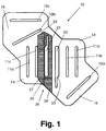
- the holding plate 10 shown in FIGS. 1 to 4 has an overall elongated shape with triangular projections 13, 14 in the central region and a region 15 which bends upward at approximately 45 ° at the upper end.
- the holding plate 10 shown in the drawing is located on the left side of a safety harness and is shown in the position in which it is when the safety harness is put on and in which its general orientation, as seen by the user, extends from the bottom left to the top right .
- the right holding plate would be a mirror image.
- a total of four first slot-shaped bushings 11a, b, c, d are arranged in the middle of the holding plate 10.
- the first bushings 11 run vertically and are aligned horizontally, i.e. the lower and upper ends of the first bushings 11 lie on a horizontal straight line.
- the first bushings 11 serve to carry out an abdominal belt B.
- Second slot-shaped bushings 12 are used to guide the front belt area S of a shoulder-seat belt.
- a total of three second bushings 12a, b, c are provided.
- the second bushings 12 are arranged approximately along a straight line and in alignment with one another, i.e. their ends lie on a straight line. This runs at an angle of approximately 45 ° to the horizontal. Since the holding plate 10 is shown in its actual position in FIG. 1, the lower right end in FIG. 1 is the end 16 near the seat and the kinking region 15 at the top left is the end of the holding plate 10 near the chest.
- the second bushing 12a at the end 16 near the seat is arranged at right angles to the alignment line.
- the second bushing 12b in the end 15 of the holding plate 10 near the chest is tilted into the horizontal by approximately 10 ° in order to deflect the direction of the front belt region S somewhat into the vertical.
- the second passage 12c arranged above it runs horizontally and also does not align with the other second bushings 12a and 12b in order, if necessary, to completely redirect the front belt area S into the vertical.
- Two overlap passages 20 and 21 are formed between the middle first passages 11b and 11c and the second passages 12a and 12b. While the first and second bushings 11, 12 all have a constant slot width, the overlap bushings 20, 21 are graduated in the slot width at 22, 23. The mutually facing edges of the overlap feed-throughs 20 and 21 are straight and the steps 22 and 23 are located in the mutually facing edges of the overlap feed-throughs 20 and 21.
- the slot width is larger, namely approximately twice the width of the first and second passages 11, 12 and the downwardly protruding area of the overlap passage 20 and the upwardly protruding area of the overlap passage 21.
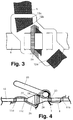
- the belts are pulled in or threaded in such a way that first the front belt region S of the shoulder-seat belt is threaded, from above through the second passage 12a near the seat and then alternately from below and above through the overlapping passages 20 and 21 and the second passage 12b near the chest (FIG. 2) and, if the front belt area S is to be continued vertically upward, also through the uppermost second passage 12c (FIG. 3).
- the front belt area S runs between the overlap feed-throughs 20 and 21 on the outside or top of the holding plate 10 and extends over the entire length of the overlap feed-throughs 20, 21.
- the front belt area S is still guided through a retaining eye in the form of a D-ring 25.
- the abdominal belt B is then passed from below through the first passage 11a and then alternately from above and below through the further first passages 11b to d and the overlap passages 20, 21. Between the overlap feed-throughs 20 and 21, it runs on the outer or upper side of the holding plate 10 and above the front belt area S through the holding eyelet 35.
- the overlap feed-through 21 near the chest is located in the area of a reinforcement 26 of the holding plate 10.
- the reinforcement 26 extends parallel to the first feed-throughs 11 and has the shape of a flat, isosceles triangle in cross section, so that it is roof-shaped overall. It has a sloping surface 27 and 28 near the chest and near the seat, which meet on a ridge line 29.
- the overlap passage 21 close to the chest is located completely in the inclined surface 28 near the seat, one edge of the overlap passage 21 coinciding with the ridge line 29.
- the inclined surface 27 near the chest extends to the following first passage 11c.
- the reinforcement 26 is located on both the top and the bottom of the holding plate 10 so that it can be used on the left or right.
- the roof-like reinforcement 26 ensures that the retaining eyelet 25 cannot tilt to the left, as seen in FIG. 4, to the extent that it can lie on the waist belt B.
- the retaining eyelet 25 can only lie to the left according to the angle of the inclined surface 28 near the seat, as a result of which a connecting element, e.g. a snap hook that can be hooked in more easily.
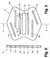
- 5 to 8 show an embodiment of the holding plate 10 for fixing back belts R1 and R2.
- FIG. 5 shows the holding plate 10 from the front, ie from the side that faces away from the person who put on the safety harness.
- the holding plate 10 is approximately hexagonal, the two vertically running edges being slightly curved inwards.
- the holding plate 10 has a total of six slot-like bushings or openings, namely two first bushings 11a, b for the first back belt R1, two second bushings 12a, b for the second back belt R2 and two overlap bushings 20, 21 through which both back belts R1, R2 pass will.
- the first bushings 11a, b are arranged parallel to one another in the top left and bottom right in FIG. 1 and approximately parallel to the edge of the holding plate 10 there.
- the second bushings 12a, b are horizontally offset somewhat inwards from the first bushings 11 and, viewed vertically, each overlap somewhat with the first bushings 11.
- the overlapping bushings 20, 21 run horizontally in the central region of the holding plate 10 at a distance of about 25 mm. While the first and second bushings 11, 12 are each approximately rectangular and have a uniform slot width, the overlap bushings 20, 21 each have a central region 17 and edge regions 18, 19, the central region 17 having approximately twice the slot width as the peripheral regions 18, 19. The width of the overlap bushing 20, 21 is reduced in the transition between the central region 17 and the left edge region 18 only at the upper edge, so that a step 30 is present there.
- the width of the overlap bushings 20, 21 is reduced at the transition between the central region 17 and the right edge region at the lower edge, so that there is a step 31 here.
- the holding plate 10 is smooth at the corresponding point.
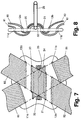
- FIGS. 7 and 8 show the holding plate with retracted back straps R1 and R2.
- the first back strap R1 runs from top left to bottom right, while the second back strap R2 runs from top right to bottom left.
- the first back belt R1 is drawn from the front visible in FIGS. 5 and 7 through the upper first passage 11a to the rear, comes through the upper overlap passage 20, namely through the central region 17 and the left edge region 18, onto the Front side, from here through the lower overlap lead-through 21, specifically through the central region and the right edge region, again on the rear side and then through the lower first lead-through 11 b again onto the front side.
- the second back strap R2 runs from the front through the upper second passage 12a to the rear of the holding plate 10, from there under the first back strap R1 through the upper overlap passage 20, namely through its central region 17 and right edge region 19 to the top, whereby now the second back strap R2 lies above the first back strap R1, from there through the lower overlap lead-through 21, namely through its central region and left edge region to the underside and from there finally through the lower second lead-through 12b to the front of the holding plate 10.
- the two back belts R1 and R2 run between the overlap passages 20, 21 through a D-shaped catch eye 25 and thereby hold them in the cutout 32.
- the catch eye 25 is fixed. A slipping of the back belts R1, R2 is prevented by the graded slot width of the overlap bushings 20, 21.
Landscapes
- Health & Medical Sciences (AREA)
- General Health & Medical Sciences (AREA)
- Business, Economics & Management (AREA)
- Emergency Management (AREA)
- Emergency Lowering Means (AREA)
- Electric Cable Arrangement Between Relatively Moving Parts (AREA)
Abstract
Die Halteplatte (10) ist Teil eines Sicherheitsgeschirrs und dient zur Führung eines ersten Gurtes (B) und eines zweiten Gurtes (S), die sich innerhalb der Halteplatte (10) kreuzen. Die Halteplatte (10) weist mindestens eine schlitzförmigen Überlappungsdurchführung (20, 21) für beide Gurte (B, S) auf, sowie Mittel, z.B. schlitzförmige Durchführungen (11a, b, c; 12a, b, c) für den ersten oder zweiten Gurt (B, S) und/oder eine oder mehrere weitere Überlappungsdurchführung (20, 21) für beide Gurte (B, S), um die beiden Gurte (B, S) so zu führen, daß zumindest einer der beiden Gurte innerhalb der Überlappungsdurchführung nur teilweise von dem anderen Gurt überlappt wird, wobei die mindestens eine Überlappungsdurchführung (20, 21) eine abgestufte Schlitzbreite hat und sich die größere Schlitzbreite in dem Bereich befindet, in dem sich der erste und der zweite Gurt (B, S) im eingezogenen Zustand innerhalb der Überlappungsdurchführung (20, 21) überlappen.
Description
Die Erfindung betrifft eine Halteplatte für ein Sicherheitsgeschirr zur Führung von zwei sich kreuzenden Gurten. Die Halteplatte hat mindestens eine schlitzförmige Überlappungsdurchführung, durch die beide Gurte hindurchgeführt werden, wobei sich die Gurte innerhalb der Überlappungsdurchführung kreuzen. Im allgemeinen weist die Halteplatte zusätzlich eine Anzahl erster schlitzförmiger Gurt-Durchführungen für den ersten Gurt und eine Anzahl zweiter schlitzförmiger Gurt-Durchführungen für den zweiten Gurt auf. Gegenstand der Erfindung ist ferner ein Sicherheitsgeschirr mit einer solchen Halteplatte.The invention relates to a holding plate for a safety harness for guiding two intersecting belts. The holding plate has at least one slit-shaped overlap lead-through, through which both straps are passed, the straps crossing within the overlap lead-through. In general, the holding plate additionally has a number of first slot-shaped belt bushings for the first belt and a number of second slot-shaped belt bushings for the second belt. The invention further relates to a safety harness with such a holding plate.
Bei Sicherheitsgeschirren sind verschiedene Gurtführungen bekannt. Im allgemeinen weisen sie einen Bauchgurt mit Verschlüssen auf der Vorderseite und ein Paar vom Rücken ausgehender, sich in Schulterblatthöhe kreuzender Rückengurte auf, die nach oben als Schultergurte und sich daran anschließende vordere Gurtbereiche fortgeführt sind. Die vorderen Gurtbereiche sind unten als Sitzgurt zusammengeführt, wobei von dessen mittlerem Bereich Beingurte abgehen, die an die unteren Enden der Rückengurte anschließbar sind. Es ist auch möglich, die schrägverlaufenden Sitzgurte nach oben zu einer Verschlußöse im Brustbereich weiterlaufen zu lassen. Wichtig ist dabei eine möglichst gleichmäßige Kraftverteilung auf den Rücken und das Gesäß bei der Arbeitsplatz-Positionierung. Die Halteplatten werden in zwei- oder dreifacher Ausführung für ein Sicherheitsgeschirr verwendet, nämlich zur Fixierung der beiden Rückengurte sowie zur Fixierung eines den Bauchgurt kreuzenden vorderen Gurtbereiches eine Schulter-Sitz-Gurtes. Die Handhabung dieser Halteplatten wird dadurch erschwert, daß stets darauf geachtet werden muß, daß sich keiner der Gurte beim Durchziehen durch die Durchführungen faltet.Various belt guides are known for safety harnesses. In general, they have an abdominal belt with fastenings on the front and a pair of back belts, which extend from the back and intersect at the shoulder blade height, and which are continued upward as shoulder belts and adjoining front belt regions. The front belt areas are brought together at the bottom as a seat belt, with leg straps extending from the central area thereof, which can be connected to the lower ends of the back belts. It is also possible to let the sloping seat belts continue to run upwards to a locking eye in the chest area. It is important that the force is distributed as evenly as possible on the back and buttocks when positioning the workstation. The holding plates are used in two or three versions for a safety harness, namely for fixing the two back belts and for fixing a front belt area crossing the waist belt, a shoulder-seat belt. The handling of these holding plates is made more difficult by the fact that it must always be ensured that none of the belts folds when pulled through the bushings.
Eine solche Halteplatte ist aus US-A-5,433,289 und DE-C-28 24 734 bekannt. Diese Halteplatte weist eine Gurt-Durchführung für jeweils den ersten und den zweiten Gurt auf sowie eine Überlappungsdurchführung, durch die beide Gurte gezogen sind: Die Überlappungsdurchführung ist ein Schlitz gleichförmiger Breite.Such a holding plate is known from US-A-5,433,289 and DE-C-28 24 734. This holding plate has a belt feed-through for each of the first and second belts and an overlap feed-through, through which both belts are pulled: the overlap feed-through is a slot of uniform width.
Eine Halteplatte mit zwei schlitzförmigen Gurt-Durchführungen ist aus EP-A-0 584 521 bekannt. Sie wird dort als Schnalle bezeichnet. Die beiden Gurte kreuzen sich innerhalb der Schnalle. Die Schnalle verschiebt sich relativ leicht und es besteht auch hier die Gefahr, daß sich einer der Gurte in Längsrichtung faltet.A holding plate with two slit-shaped belt bushings is known from EP-A-0 584 521. It is called a buckle there. The two straps cross within the buckle. The buckle moves relatively easily and there is also the risk that one of the straps folds in the longitudinal direction.
Halteplatten sind ferner aus EP-A-0 508 278, DE-A-28 24 734 und DE-U-89 14 878 bekannt. Sie dienen dazu, den Kreuzungspunkt der Rückengurte zu fixieren und dadurch für den richtigen Sitz des Sicherheitsgeschirrs zu sorgen. Die Durchführungen haben dabei gleichförmige Breite.Holding plates are also known from EP-A-0 508 278, DE-A-28 24 734 and DE-U-89 14 878. They serve to fix the crossing point of the back belts and thereby ensure that the safety harness is properly seated. The bushings have a uniform width.
Der Erfindung liegt die Aufgabe zugrunde, eine Halteplatte zur Führung von zwei Gurten in deren Kreuzungsbereich zu schaffen, beispielsweise von zwei Rückengurten oder des Bauchgurtes und des Schulter-Sitz-Gurtes. Die Halteplatte soll die beiden Gurte in diesem Bereich fixieren, die Gefahr des Faltens der Gurte weitgehend beseitigen und einfach handzuhaben sein.The invention has for its object to provide a holding plate for guiding two belts in their intersection, for example two back belts or the waist belt and the shoulder-seat belt. The holding plate is intended to fix the two belts in this area, largely eliminate the risk of the belts folding and be easy to handle.
Erfindungsgemäß wird diese Aufgabe dadurch gelöst, daß die Halteplatte Mittel aufweist, um die beiden Gurte so zu führen, daß zumindest einer der beiden Gurte innerhalb der Überlappungsdurchführung sich nur teilweise mit dem anderen Gurt überlappt, und daß die mindestens eine Überlappungsdurchführung eine abgestufte Schlitzbreite hat, wobei sich die größere Schlitzbreite in dem Bereich befindet, in dem sich der erste und der zweite Gurt im eingezogenen Zustand innerhalb der Überlappungsdurchführung teilweise überlappen.According to the invention, this object is achieved in that the holding plate has means for guiding the two belts such that at least one of the two belts only partially overlaps with the other belt within the overlap bushing and that the at least one overlapping bushing has a graduated slot width, wherein the larger slot width is in the area in which the first and the second belt partially overlap in the retracted state within the overlap passage.
Die Mittel zur Führung der beiden Gurte derart, daß zumindest einer der beiden Gurte nur teilweise von dem anderen überlappt wird, können in einer entsprechenden Anordnung der eingangs erwähnten ersten und zweiten Durchführungen bestehen oder in einer oder mehreren weiteren Überlappungsdurchführungen, innerhalb der sich beide Gurte vollständig oder teilweise überlappen. Im allgemeinen sind zwei Überlappungsdurchführungen vorgesehen, in denen sich die Gurte nur teilweise überlappen, wobei sich die Stelle der vollständigen Überlappung zwischen beiden Überlappungsdurchführungen befindet, und ist vor und nach der oder den Überlappungsdurchführungen zumindest eine erste Durchführung nur für den ersten Gurt und eine zweite Durchführung nur für den zweiten Gurt vorgesehen.The means for guiding the two belts in such a way that at least one of the two belts is only partially overlapped by the other can consist in a corresponding arrangement of the first and second bushings mentioned at the beginning or in one or more further overlapping bushings within which both belts are completely or partially overlap. In general, two overlap feedthroughs are provided in which the belts only partially overlap, the point of complete overlap being between the two overlap feedthroughs, and before and after the overlap feedthroughs is at least a first feedthrough only for the first belt and a second feedthrough only intended for the second belt.
Durch die erfindungsgemäße Ausbildung ist die Überlappungsdurchführung in ihrem Umriß dem kombinierten Querschnittsprofil der sich im eingezogenen Zustand kreuzenden Gurte an dieser Stelle angepaßt. Durch die Anpassung des Umrisses der Überlappungsdurchführung an das Querschnittsprofil der sich überlappenden Gurte wird ein seitliches Verrutschen und ein Falten der Gurte verhindert.Due to the design according to the invention, the outline of the overlap bushing is adapted to the combined cross-sectional profile of the belts which intersect in the retracted state at this point. By adapting the outline of the overlap feedthrough to the cross-sectional profile of the overlapping belts, lateral slipping and folding of the belts is prevented.
Vorzugsweise fluchtet der Bereich der größeren Schlitzbreite der Überlappungsdurchführung sowohl mit den ersten Durchführungen als auch mit den zweiten Durchführungen. Dadurch wird sichergestellt, daß die Gurte im Bereich der Halteplatte nicht seitlich abknicken. Vorzugsweise wird die Überlappungsdurchführung oder die Überlappungsdurchführungen zwischen zwei der ersten und/oder zwei der zweiten Durchführungen angeordnet.The area of the larger slot width of the overlap bushing is preferably aligned with both the first bushings and the second bushings. This ensures that the straps do not kink laterally in the area of the holding plate. The overlap bushing or the overlap bushings is preferably arranged between two of the first and / or two of the second bushings.
Derartige Halteplatten werden insbesondere zur Führung eines Bauchgurtes und eines den Bauchgurt kreuzenden vorderen Gurtbereichs eines Schulter-Sitz-Gurtes eines Sicherheitsgeschirrs eingesetzt. Der Bauchgurt wird dabei durch die ersten Durchführungen gezogen und diese sind längs einer etwa waagrecht verlaufenden Geraden nebeneinander angeordnet. Der vordere Gurtbereich wird durch die zweiten Durchführungen gezogen, die längs einer schrägverlaufenden Geraden angeordnet sind. Die ersten und die zweiten Durchführungen sind dabei jeweils etwa rechtwinklig zu der Geraden ausgerichtet, entlang der sie angeordnet sind. Für die ersten Durchführungen bedeutet dies, daß sie etwa senkrecht ausgerichtet sind, während die zweiten Durchführungen eine Ausrichtung von etwa 45° zur Senkrechten haben. Dies gilt im allgemeinen allerdings nur für die sitznahen zweiten Durchführungen, das sind die zweiten Durchführungen unterhalb der Überlappungsdurchführungen.Such holding plates are used in particular for guiding an abdominal belt and a front belt region of a shoulder-seat belt of a safety harness crossing the abdominal belt. The waist belt is pulled through the first bushings and these are arranged next to each other along an approximately horizontal straight line. The front one The belt area is drawn through the second bushings, which are arranged along an oblique straight line. The first and the second bushings are each aligned approximately at right angles to the straight line along which they are arranged. For the first bushings, this means that they are aligned approximately vertically, while the second bushings have an orientation of approximately 45 ° to the vertical. In general, however, this only applies to the second bushings close to the seat, i.e. the second bushings below the overlapping bushings.
Die Ausrichtung des oder der brustnahen zweiten Durchführungen hängt vom beabsichtigten Verlauf des vorderen Gurtbereichs im Brustbereich ab. Je mehr sich der Verlauf der Senkrechten nähert, desto stärker ist die brustnahe Durchführung in die Waagrechte gekippt. Sind mehrere brustnahe zweite Durchführungen vorgesehen, so sind die Durchführungen schrittweise stärker gekippt. Vorzugsweise sind mehrere brustnahe zweite Durchführungen vorgesehen, die aufeinanderfolgend stärker zur Waagrechten gekippt sind, wobei der Gurt jeweils nur bis zu der Durchführung eingefädelt wird, die ihm den gewünschten Verlauf gibt.The alignment of the second feedthroughs close to the chest depends on the intended course of the front belt area in the chest area. The closer the course of the vertical approaches, the more the breast-near passage is tilted into the horizontal. If several breast passages close to the chest are provided, the bushings are gradually tilted more. Preferably, a plurality of second passages close to the chest are provided, which are successively tilted more horizontally, the belt only being threaded up to the passage which gives it the desired course.
Vorzugsweise sind zwei Überlappungsdurchführungen vorgesehen. Sie sind wie die ersten Durchführungen senkrecht ausgerichtet. Zwischen den Überlappungsdurchführungen werden zweckmäßig beide Gurte auf der Außenseite, d.h. körperfernen Seite, der Halteplatte und dabei gleichzeitig durch eine Halteöse, z.B. einen D-förmigen Ring, geführt, der als Anschlagpunkt für einen Sicherungsgurt oder Haltegurt dient. Die beiden Gurte kreuzen sich in der Halteöse. Der Schulter-Sitz-Gurt liegt im Überlappungsbereich zweckmäßig unmittelbar an der Halteplatte bzw. der Halteöse an, während der Bauchgurt darüber liegt.Two overlap bushings are preferably provided. Like the first bushings, they are aligned vertically. Between the overlap feed-throughs, both belts are expediently guided on the outside, ie the side remote from the body, of the holding plate and at the same time through a holding eye, for example a D-shaped ring, which serves as an attachment point for a safety belt or holding belt. The two straps cross in the eyelet. The shoulder-seat belt is expediently in the overlap area directly against the holding plate or the eyelet, while the abdominal belt lies above it.
Im Bereich der brustnahen Überlappungsdurchführung ist die Halteplatte vorzugsweise durch eine dachkantartige Auflage verstärkt, wobei die Firstlinie der dachkantartigen Verstärkung mit dem brustnahen Rand der brustnahen Überlappungsdurchführung zusammenfällt, so daß sich diese Überlappungsdurchführung in der sitznahen Schrägfläche der dachkantartigen Verstärkung befindet. Diese Schrägfläche geht etwa längs der Mittellinie zwischen den beiden Überlappungsdurchführungen in die Ebene der Halteplatte über. Die brustnahe Schrägfläche der dachkantartigen Verstärkung erstreckt sich dagegen bis zur nachfolgenden ersten Durchführung. Durch die dachkantartige Verstärkung wird erreicht, daß die Halteöse etwas absteht und dadurch ein Verbindungselement, z.B. ein Karabinerhaken, leichter eingehakt werden kann. Die dachkantartige Verstärkung ist auf beiden Seiten der Halteplatte angebracht, damit sie sowohl auf der rechten als auch auf der linken Körperseite verwendbar ist.In the area of the overlap feedthrough near the chest, the holding plate is preferably reinforced by a roof-like support, the ridge line of the roof-like reinforcement coinciding with the edge of the overlap feedthrough near the chest, so that this overlap feedthrough is located in the sloping surface of the roof-like reinforcement near the seat. This inclined surface merges into the plane of the holding plate approximately along the center line between the two overlap passages. The sloping surface of the roof-like reinforcement close to the chest, on the other hand, extends to the subsequent first implementation. The roof-like reinforcement ensures that the retaining eyelet protrudes somewhat, thereby creating a connecting element, e.g. a snap hook that can be hooked in more easily. The roof-like reinforcement is attached to both sides of the holding plate so that it can be used on both the right and left side of the body.
Ein Sicherheitsgeschirr weist im allgemeinen zwei derartige Halteplatten auf, nämlich im Kreuzungsbereich jedes der Schulter-Sitz-Gurte und des Bauchgurtes. Zwischen den beiden Halteplatten befindet sich dabei der Verschluß des Bauchgurtes.A safety harness generally has two such holding plates, namely in the area of intersection of each of the shoulder-seat belts and the abdominal belt. The closure of the waist belt is located between the two holding plates.
Ein anderer typischer Anwendungsfall der erfindungsgemäßen Halteplatte ist die Fixierung der sich kreuzenden Rückengurte. Auch hier soll die Halteplatte die Möglichkeit bieten, an den sich kreuzenden Rückengurten zusätzlich ein Verbindungselement, z.B. eine Auffangöse, anzubringen, ohne daß die Rückengurte übereinanderrutschen können.Another typical application of the holding plate according to the invention is the fixing of the intersecting back straps. Here, too, the holding plate should offer the possibility of an additional connecting element on the intersecting back straps, e.g. a catch eye to attach without the back straps can slide over each other.
Bei Halteplatten für Rückengurte liegen die Überlappungsdurchführungen allgemein waagrecht in einem Abstand oberhalb und unterhalb der horizontalen Linie, auf der sich die beiden Rückengurte vollständig überlappen, d.h. der horizontalen Diagonale der durch den Überlappungsbereich gebildeten Raute. Der Abstand zwischen den Überlappungsdurchführungen beträgt dabei allgemein mindestens etwa 25 mm, damit Verbindungselemente, z.B. in Form eines Gurtbandes dieser Breite, an dieser Stelle um die beiden sich kreuzenden Rückengurte gelegt werden kann.In the case of retaining plates for back belts, the overlap bushings are generally horizontally at a distance above and below the horizontal line on which the two back belts overlap completely, ie the horizontal diagonal of the rhombus formed by the overlap area. The distance between the overlap bushings is generally at least about 25 mm, so that connecting elements, for example in the form of a webbing of this width, can be placed at this point around the two intersecting back belts.
Vorzugsweise ist zwischen den Überlappungsdurchführungen an der Stelle der horizontalen Diagonale der Überlappungsraute eine Aussparung vorgesehen, die ein Verbindungselement in Form einer Auffangöse an ihrem Platz hält. Durch die Auffangöse sind die beiden Rückengurte gezogen.Preferably, a recess is provided between the overlap feedthroughs at the location of the horizontal diagonal of the overlap diamond, which holds a connecting element in the form of a collecting eye in place. The two back straps are pulled through the eyelet.
Vorzugsweise verlaufen die ersten Durchführungen parallel zueinander, und ebenso die zweiten Durchführungen, wobei die ersten Durchführungen jedoch unter einem Winkel zu den zweiten Durchführungen verlaufen. Dadurch sind die zusammengehörigen Durchführungen sofort erkennbar und ist ein Vertauschen der Rückengurte beim Einziehen in die Halteplatte kaum noch möglich.The first bushings preferably run parallel to one another, and likewise the second bushings, but the first bushings run at an angle to the second bushings. As a result, the associated bushings are immediately recognizable and it is hardly possible to swap the back straps when pulling them into the holding plate.
Eine insgesamt besonders kleine Abmessung einer Halteplatte für Rückengurte ergibt sich, wenn sich die obere erste und die obere zweite Durchführung und die untere erste und die untere zweite Durchführung in der Vertikalen gesehen teilweise überlappen.An overall particularly small dimension of a holding plate for back belts results when the upper first and upper second bushings and the lower first and lower second bushings partially overlap as seen in the vertical.
Das Einziehen der Rückengurte erfolgt bei dieser Ausführungsform in der Weise, daß der eine Rückengurt von der Vorderseite der Halteplatte her, das ist die von der Person abgewandten Seite, durch die obere erste Durchführung zur Rückseite der Halteplatte hin verläuft, dann von der Rückseite her durch die obere Überlappungsdurchführung hindurch wieder zur Vorderseite gelangt, dann eventuell durch eine Auffangöse gezogen wird und durch die untere Überlappungsdurchführung hindurch wieder zur Rückseite gelangt, von der aus sie dann durch die untere erste Durchführung wieder auf die Vorderseite gelangt und hier die Rückenplatte wieder verläßt. Entsprechend ist der zweite Rückengurt durch die obere zweite, die beiden Überlappungs- und die untere zweite Durchführung gezogen. Durch diesen Verlauf der Rückengurte innerhalb der Halteplatte biegt sich diese bei einem Absturz durch und kann dadurch den auftretenden Fangstoß etwas dämpfen.In this embodiment, the back straps are drawn in in such a way that the one back strap runs from the front of the holding plate, that is to say the side facing away from the person, through the upper first passage to the rear of the holding plate, then from the rear the upper overlap lead through to the front again, then possibly pulled through a catch eye and through the lower overlap lead back to the back, from which it then reaches the front through the lower first lead-through and leaves the back plate again. The second back belt is correspondingly through the upper one second, the two overlapping and the lower second passage pulled. Due to this course of the back straps within the holding plate, it bends in the event of a fall and can thus dampen the impact force that occurs.
Die Halteplatte besteht im allgemeinen aus einer etwa 4 mm starken Kunststoff- oder Leichtmetallplatte.The holding plate generally consists of an approximately 4 mm thick plastic or light metal plate.
Ausführungsbeispiele der Erfindung werden nachfolgend anhand der Zeichnung naher erläutert. Es zeigen:
- Fig. 1
- eine-linke Halteplatte für einen Bauchgurt und einen diesen kreuzenden vorderen Gurtbereich eines Schulter-Sitz-Gurtes in Draufsicht;
- Fig. 2
- die Halteplatte von Fig. 1 mit eingezogenen Gurten;
- Fig. 3
- die Halteplatte von Fig. 1, wobei der Schulter-Sitz-Gurt so eingezogen ist, daß er stärker senkrecht verläuft;
- Fig. 4
- die Halteplatte mit eingezogenen Gurten in Seitenansicht;
- Fig. 5
- eine Halteplatte für die Fixierung von Rückengurten in Draufsicht;
- Fig. 6
- die Halteplatte von Fig. 5 im Schnitt nach 6-6;
- Fig. 7
- die Halteplatte mit eingezogenen Rückengurten und Auffangöse und
- Fig. 8
- die Halteplatte mit eingezogenen Rückengurten und Auffangöse von der Seite.
- Fig. 1
- a left-hand holding plate for an abdominal belt and a front belt region of a shoulder-seat belt crossing this, in a top view;
- Fig. 2
- the holding plate of Figure 1 with straps retracted.
- Fig. 3
- the holding plate of Figure 1, the shoulder-seat belt is retracted so that it is more vertical;
- Fig. 4
- the holding plate with retracted belts in side view;
- Fig. 5
- a holding plate for fixing back straps in plan view;
- Fig. 6
- the holding plate of Figure 5 in section after 6-6.
- Fig. 7
- the holding plate with retracted back straps and catch eye and
- Fig. 8
- the holding plate with retracted back straps and catch eye from the side.
Die in Fig. 1 bis 4 dargestellte Halteplatte 10 hat eine insgesamt längliche Form mit dreieckförmigen Ansätzen 13, 14 im mittleren Bereich und einem unter etwa 45° nach oben abknickenden Bereich 15 am oberen Ende. Die in der Zeichnung dargestellte Halteplatte 10 befindet sich auf der linken Seite eines Sicherheitsgeschirrs und ist in der Lage dargestellt, in der sie sich bei angelegtem Sicherheitsgeschirr befindet und in der sich ihre allgemeine Ausrichtung, vom Benutzer aus gesehen, von links unten nach rechts oben erstreckt. Die rechte Halteplatte wäre spiegelbildlich dazu.The holding
Insgesamt vier erste schlitzförmige Durchführungen 11a, b, c, d sind in der Mitte der Halteplatte 10 angeordnet. Die ersten Durchführungen 11 laufen dabei senkrecht und fluchten in der Waagrechten, d.h. die unteren und oberen Enden der ersten Durchführungen 11 liegen auf einer waagrechten Geraden. Die ersten Durchführungen 11 dienen dabei zur Durchführung eines Bauchgurtes B.A total of four first slot-shaped
Zweite schlitzförmige Durchführungen 12 dienen zur Führung des vorderen Gurtbereichs S eines Schulter-Sitz-Gurtes. Insgesamt sind drei zweite Durchführungen 12a, b, c vorgesehen. Die zweiten Durchführungen 12 sind ungefähr längs einer Geraden und miteinander fluchtend angeordnet, d.h. ihre Enden liegen jeweils auf einer Geraden. Diese verläuft unter einem Winkel von etwa 45° zur Waagrechten. Da die Halteplatte 10 in Fig. 1 in ihrer tatsächlichen Lage dargestellt ist, ist das in Fig. 1 untere rechte Ende das sitznahe Ende 16 und der links oben liegende, abknickende Bereich 15 das brustnahe Ende der Halteplatte 10.Second slot-shaped bushings 12 are used to guide the front belt area S of a shoulder-seat belt. A total of three
Die zweite Durchführung 12a am sitznahen Ende 16 ist rechtwinklig zu der Fluchtungsgeraden angeordnet. Die zweite Durchführung 12b im brustnahen Ende 15 der Halteplatte 10 ist dagegen um etwa 10° in die Waagrechte gekippt, um die Richtung des vorderen Gurtbereichs S etwas in die Senkrechte umzulenken. Die darüber angeordnete zweite Durchführung 12c verläuft dagegen waagrecht und fluchtet auch nicht mit den anderen zweiten Durchführungen 12a und 12b, um gegebenenfalls den vorderen Gurtbereich S vollständig in die Senkrechte umzulenken.The
Zwischen den mittleren ersten Durchführungen 11b und 11c und den zweiten Durchführungen 12a und 12b sind zwei Überlappungsdurchführungen 20 und 21 ausgebildet. Während die ersten und zweiten Durchführungen 11, 12 alle eine konstante Schlitzbreite haben, sind die Überlappungsdurchführungen 20, 21 in der Schlitzbreite bei 22, 23 abgestuft. Die einander zugewandten Ränder der Überlappungsdurchführungen 20 und 21 sind dabei gerade und die Stufen 22 und 23 befinden sich in den voneinander abgewandten Rändern der Überlappungsdurchführungen 20 und 21. In dem Bereich, in dem die Überlappungsdurchführungen 20, 21 sowohl mit den ersten Durchführungen 11 als auch den zweiten Durchführungen 12a und b fluchten, ist die Schlitzbreite größer, und zwar etwa das Doppelte der Breite der ersten und zweiten Durchführungen 11, 12 und des nach unten überstehenden Bereichs der Überlappungsdurchführung 20 bzw. des nach oben überstehenden Bereichs der Überlappungsdurchführung 21.Two overlap
Das Einziehen oder Einfädeln der Gurte erfolgt in der Weise, daß zuerst der vordere Gurtbereich S des Schulter-Sitz-Gurtes eingefädelt wird, und zwar von oben durch die sitznahe zweite Durchführung 12a und dann abwechselnd von unten und oben durch die Überlappungsdurchführungen 20 und 21 und die brustnahe zweite Durchführung 12b (Fig. 2) und, falls der vordere Gurtbereich S senkrecht nach oben weitergeführt werden soll, auch durch die oberste zweite Durchführung 12c (Fig. 3). Zwischen den Überlappungsdurchführungen 20 und 21 verläuft der vordere Gurtbereich S dabei auf der Außen- oder Oberseite der Halteplatte 10 und erstreckt sich dabei über die gesamte Länge der Überlappungsdurchführungen 20, 21.The belts are pulled in or threaded in such a way that first the front belt region S of the shoulder-seat belt is threaded, from above through the
Zwischen den beiden Überlappungsdurchführungen 20, 21 ist der vordere Gurtbereich S noch durch eine Halteöse in Form eines D-Ringes 25 geführt.Between the two
Danach wird der Bauchgurt B von unten durch die erste Durchführung 11a und dann abwechselnd von oben und unten durch die weiteren ersten Durchführungen 11b bis d und die Überlappungsdurchführungen 20, 21 geführt. Zwischen den Überlappungsdurchführungen 20 und 21 verläuft er auf der Außen- oder Oberseite der Halteplatte 10 und über dem vorderen Gurtbereich S durch die Halteöse 35.The abdominal belt B is then passed from below through the
Die brustnahe Überlappungsdurchführung 21 befindet sich im Bereich einer Verstärkung 26 der Halteplatte 10. Die Verstärkung 26 erstreckt sich parallel zu den ersten Durchführungen 11 und hat im Querschnitt die Form eines flachen, gleichschenkligen Dreiecks, so daß sie insgesamt dachförmig ist. Sie hat eine brustnahe und eine sitznahe Schrägfläche 27 und 28, die sich an einer Firstlinie 29 treffen. Die brustnahe Überlappungsdurchführung 21 befindet sich vollständig in der sitznahen Schrägfläche 28, wobei der eine Rand der Überlappungsdurchführung 21 mit der Firstlinie 29 zusammenfällt. Die brustnahe Schrägfläche 27 erstreckt sich bis zur folgenden ersten Durchführung 11c. Die Verstärkung 26 befindet sich sowohl auf der Oberseite als auch der Unterseite der Halteplatte 10, so daß diese links oder rechts verwendet werden kann. Durch die dachkantartige Verstärkung 26 wird erreicht, daß sich die Halteöse 25 nach links, in Fig. 4 gesehen, nicht soweit kippen kann, daß sie sich an den Bauchgurt B legen kann. Die Halteöse 25 kann sich nur entsprechend dem Winkel der sitznahen Schrägfläche 28 nach links legen, wodurch ein Verbindungselement, z.B. ein Karabinerhaken, leichter eingehakt werden kann.The overlap feed-through 21 near the chest is located in the area of a
Die Fig. 5 bis 8 zeigen ein Ausführungsbeispiel der Halteplatte 10 für die Fixierung von Rückengurten R1 und R2.5 to 8 show an embodiment of the holding
Fig. 5 zeigt die Halteplatte 10 von der Vorderseite, d.h. von der Seite, die von der Person abgewandt ist, die das Sicherheitsgeschirr angelegt hat. Die Halteplatte 10 ist etwa sechseckig, wobei die beiden vertikal verlaufenden Ränder etwas nach innen geschwungen sind. Die Halteplatte 10 hat insgesamt sechs schlitzartige Durchführungen oder Durchbrechungen, nämlich zwei erste Durchführungen 11a, b für den ersten Rückengurt R1, zwei zweite Durchführungen 12a, b für den zweiten Rückengurt R2 und zwei Überlappungsdurchführungen 20, 21, durch die beide Rückengurte R1, R2 hindurchgeführt werden. Die ersten Durchführungen 11a, b sind in Fig. 1 links oben und rechts unten parallel zueinander und etwa parallel zu dem dortigen Rand der Halteplatte 10 angeordnet. Die zweiten Durchführungen 12a, b sind waagrecht etwas von den ersten Durchführungen 11 nach innen versetzt angeordnet und überlappen sich in der Vertikalen betrachtet jeweils etwas mit den ersten Durchführungen 11. Die Überlappungsdurchführungen 20, 21 verlaufen waagrecht in dem Mittelbereich der Halteplatte 10 in einem Abstand von etwa 25 mm. Während die ersten und zweite Durchführungen 11, 12 jeweils etwa rechteckförmig sind und gleichförmige Schlitzbreite aufweisen, haben die Überlappungsdurchführungen 20, 21 jeweils einen Mittelbereich 17 und Randbereiche 18, 19, wobei der Mittelbereich 17 etwa die doppelte Schlitzbreite wie die Randbereiche 18, 19 aufweist. Die Verringerung der Breite der Überlappungsdurchführung 20, 21 findet dabei im Übergang zwischen dem Mittelbereich 17 und dem linken Randbereich 18 nur am oberen Rand statt, so daß dort eine Stufe 30 vorhanden ist. Entsprechend findet die Verringerung der Breite der Überlappungsdurchführungen 20, 21 am Übergang zwischen dem Mittelbereich 17 und dem rechten Randbereich am unteren Rand statt, so daß hier eine Stufe 31 besteht. Zwischen den Überlappungsdurchführungen 20, 21 befindet sich an der Stelle 24 der vollständigen Überlappung der Rückengurte R1, R2 eine etwa 1 cm weite Vertiefung oder Aussparung 32. Auf der Rückseite ist die Halteplatte 10 an der entsprechenden Stelle glatt.FIG. 5 shows the holding
Die Fig. 7 und 8 zeigen die Halteplatte mit eingezogenen Rückengurten R1 und R2. Der erste Rückengurt R1 verläuft von links oben nach rechts unten, während der zweite Rückengurt R2 von rechts oben nach links unten verläuft. Der erste Rückengurt R1 ist von der in den Fig. 5 und 7 sichtbaren Vorderseite durch die obere erste Durchführung 11a hindurch zur Rückseite gezogen, kommt durch die obere Überlappungsdurchführung 20, und zwar durch den Mittelbereich 17 und den linken Randbereich 18 hindurch, wieder auf die Vorderseite, von hier durch die untere Überlappungsdurchführung 21, und zwar durch den Mittelbereich und den rechten Randbereich hindurch, wieder auf der Rückseite und dann durch die untere erste Durchführung 11b hindurch wieder auf die Vorderseite. In entsprechender Weise verläuft der zweite Rückengurt R2 von der Vorderseite durch die obere zweite Durchführung 12a zur Rückseite der Halteplatte 10, von dort unter dem ersten Rückengurt R1 durch die obere Überlappungsdurchführung 20, und zwar durch deren Mittelbereich 17 und rechten Randbereich 19 zur Oberseite, wobei nunmehr der zweite Rückengurt R2 über dem ersten Rückengurt R1 liegt, von dort durch die untere Überlappungsdurchführung 21, und zwar durch deren Mittelbereich und linken Randbereich zur Unterseite und von dort schließlich durch die untere zweite Durchführung 12b wieder zur Vorderseite der Halteplatte 10.7 and 8 show the holding plate with retracted back straps R1 and R2. The first back strap R1 runs from top left to bottom right, while the second back strap R2 runs from top right to bottom left. The first back belt R1 is drawn from the front visible in FIGS. 5 and 7 through the upper
Wie man insbesondere in Fig. 8 erkennt, verlaufen die beiden Rückengurte R1 und R2 zwischen den Überlappungsdurchführungen 20, 21 durch eine D-förmige Auffangöse 25 und halten diese dadurch in der Aussparung 32.As can be seen in particular in FIG. 8, the two back belts R1 and R2 run between the
Durch die besondere Form der Überlappungsdurchführungen 20, 21 und die Führung der beiden Rückengurte R1 und R2 zwischen den Überlappungsdurchführungen 20, 21 auf der Vorderseite wird eine Fixierung der Auffangöse 25 erreicht. Ein Übereinanderrutschen der Rückengurte R1, R2 wird dabei durch die abgestufte Schlitzbreite der Überlappungsdurchführungen 20, 21 verhindert.Due to the special shape of the overlap feed-
Durch die Ausrichtung der ersten uns zweiten Durchführungen 11, 12 ist ein Vertauschen der Rückengurte R1, R2 beim Durchziehen praktisch nicht mehr möglich. Bei der dargestellten Anordnung der Durchführungen werden alle diese Vorteile durch eine Halteplatte 10 mit minimalen Abmessungen erreicht.Due to the alignment of the first and second bushings 11, 12, swapping the back straps R1, R2 when pulling them through is practically no longer possible. In the arrangement of the bushings shown, all these advantages are achieved by a holding
Claims (10)
Applications Claiming Priority (4)
| Application Number | Priority Date | Filing Date | Title |
|---|---|---|---|
| DE29608883U | 1996-05-17 | ||
| DE29608883U DE29608883U1 (en) | 1996-05-17 | 1996-05-17 | Back plate for a safety harness |
| DE29617932U DE29617932U1 (en) | 1996-10-15 | 1996-10-15 | Holding plate for guiding an abdominal belt and a shoulder-seat belt of a safety harness crossing it |
| DE29617932U | 1996-10-15 |
Publications (2)
| Publication Number | Publication Date |
|---|---|
| EP0807451A2 true EP0807451A2 (en) | 1997-11-19 |
| EP0807451A3 EP0807451A3 (en) | 1999-02-17 |
Family
ID=26058985
Family Applications (1)
| Application Number | Title | Priority Date | Filing Date |
|---|---|---|---|
| EP97104201A Withdrawn EP0807451A3 (en) | 1996-05-17 | 1997-03-13 | Fixing plate for safety harness for guiding two crossing belts |
Country Status (1)
| Country | Link |
|---|---|
| EP (1) | EP0807451A3 (en) |
Cited By (6)
| Publication number | Priority date | Publication date | Assignee | Title |
|---|---|---|---|---|
| WO1999013947A1 (en) * | 1997-09-17 | 1999-03-25 | Rose Manufacturing Company | Full body harness for fall arrest |
| US5957091A (en) * | 1997-11-19 | 1999-09-28 | Rose Manufacturing Company | Full body harness for fall arrest |
| EP1220704A4 (en) * | 1999-10-15 | 2003-01-22 | Protecta International Inc | Full-body safety harness |
| WO2004033045A1 (en) * | 2002-10-04 | 2004-04-22 | Mine Safety Appliances Company | Full body harness for fall arrest |
| JP2015080578A (en) * | 2013-10-22 | 2015-04-27 | 株式会社谷沢製作所 | Safety belt |
| WO2020077189A1 (en) | 2018-10-12 | 2020-04-16 | Msa Technology, Llc | Harness back plate and strap arrangement |
Family Cites Families (2)
| Publication number | Priority date | Publication date | Assignee | Title |
|---|---|---|---|---|
| DE8914878U1 (en) * | 1989-12-20 | 1991-04-18 | Mittelmann Armaturen GmbH + Co KG, 5603 Wülfrath | Safety harness for people at risk of falling |
| DE4224334A1 (en) * | 1992-07-23 | 1994-01-27 | Manfred Meckel Fabrik Fuer Sic | Safety harness to secure a person when working at exposed and / or high work places |
-
1997
- 1997-03-13 EP EP97104201A patent/EP0807451A3/en not_active Withdrawn
Cited By (11)
| Publication number | Priority date | Publication date | Assignee | Title |
|---|---|---|---|---|
| WO1999013947A1 (en) * | 1997-09-17 | 1999-03-25 | Rose Manufacturing Company | Full body harness for fall arrest |
| AU731313B2 (en) * | 1997-09-17 | 2001-03-29 | Rose Manufacturing Company | Full body harness for fall arrest |
| US5957091A (en) * | 1997-11-19 | 1999-09-28 | Rose Manufacturing Company | Full body harness for fall arrest |
| EP1220704A4 (en) * | 1999-10-15 | 2003-01-22 | Protecta International Inc | Full-body safety harness |
| WO2004033045A1 (en) * | 2002-10-04 | 2004-04-22 | Mine Safety Appliances Company | Full body harness for fall arrest |
| US6804830B2 (en) | 2002-10-04 | 2004-10-19 | Mine Safety Appliances Company | Full body harness for fall arrest |
| CN1688366B (en) * | 2002-10-04 | 2010-05-26 | 矿井安全装置公司 | Integral harness for fall protection |
| JP2015080578A (en) * | 2013-10-22 | 2015-04-27 | 株式会社谷沢製作所 | Safety belt |
| WO2020077189A1 (en) | 2018-10-12 | 2020-04-16 | Msa Technology, Llc | Harness back plate and strap arrangement |
| EP3863733A4 (en) * | 2018-10-12 | 2021-12-01 | MSA Technology, LLC | HARNESS BACK PLATE AND STRAP ARRANGEMENT |
| US11497948B2 (en) | 2018-10-12 | 2022-11-15 | Msa Technology, Llc | Harness back plate and strap arrangement |
Also Published As
| Publication number | Publication date |
|---|---|
| EP0807451A3 (en) | 1999-02-17 |
Similar Documents
| Publication | Publication Date | Title |
|---|---|---|
| DE2917327C2 (en) | Buckle for adjustable connection of strap ends | |
| DE2630778C2 (en) | Box pallet, transport crate or storage container | |
| DE3007645A1 (en) | SAFETY SEAT FOR MOTOR VEHICLES | |
| DE69902348T2 (en) | BIDEXTIONAL LOCKING DEVICE FOR FALL PROTECTION | |
| DE102012000202B4 (en) | Device for anchoring a belt buckle and device arrangement with at least two such devices | |
| DE69413580T2 (en) | Adjustable buckle with self-locking belt attachment | |
| DE2923283C2 (en) | ||
| DE3242696A1 (en) | FASTENING DEVICE FOR A BRACKET BRACKET, ESPECIALLY FOR MOTOR VEHICLE SAFETY BELTS | |
| DE69412269T2 (en) | PROTECTIVE SHEET MADE OF PLATES WITH RINGS CONNECTED AND APRON FROM THEM | |
| DE4108433A1 (en) | HEIGHT-ADJUSTABLE TUBE SUSPENSION | |
| EP0239903B1 (en) | Snap hook, particularly for mountaineering | |
| EP0807451A2 (en) | Fixing plate for safety harness for guiding two crossing belts | |
| DE102009025380A1 (en) | Radiation protection order | |
| DE69914123T2 (en) | Buckle for a seat belt | |
| EP0389831A2 (en) | Device for binding elongated objects | |
| DE2824734C2 (en) | Climbing belt | |
| DE3342453C2 (en) | Zipper slider | |
| AT398322B (en) | FLOATING OIL AND CHEMICAL BARRIERS | |
| DE69201340T2 (en) | Device for automatically coupling a seat belt anchor to the floor of a vehicle. | |
| DE2849905C2 (en) | ||
| DE2830187C2 (en) | Armrests for vehicles | |
| DE29617932U1 (en) | Holding plate for guiding an abdominal belt and a shoulder-seat belt of a safety harness crossing it | |
| DE8914878U1 (en) | Safety harness for people at risk of falling | |
| DE102012014693A1 (en) | Closure element for detachable connection of two belts of safety harness, has slider with passage opening for through feeding of belt end, and another passage opening for through feeding of belt end and bar between two passage openings | |
| DE102013019343A1 (en) | Multifunctional eyelet in a safety harness |
Legal Events
| Date | Code | Title | Description |
|---|---|---|---|
| PUAI | Public reference made under article 153(3) epc to a published international application that has entered the european phase |
Free format text: ORIGINAL CODE: 0009012 |
|
| AK | Designated contracting states |
Kind code of ref document: A2 Designated state(s): DE FR GB IT |
|
| PUAL | Search report despatched |
Free format text: ORIGINAL CODE: 0009013 |
|
| AK | Designated contracting states |
Kind code of ref document: A3 Designated state(s): DE FR GB IT |
|
| 17P | Request for examination filed |
Effective date: 19990608 |
|
| STAA | Information on the status of an ep patent application or granted ep patent |
Free format text: STATUS: THE APPLICATION IS DEEMED TO BE WITHDRAWN |
|
| 18D | Application deemed to be withdrawn |
Effective date: 20031001 |