EP0807427B1 - Modular wheelchair - Google Patents
Modular wheelchair Download PDFInfo
- Publication number
- EP0807427B1 EP0807427B1 EP97106524A EP97106524A EP0807427B1 EP 0807427 B1 EP0807427 B1 EP 0807427B1 EP 97106524 A EP97106524 A EP 97106524A EP 97106524 A EP97106524 A EP 97106524A EP 0807427 B1 EP0807427 B1 EP 0807427B1
- Authority
- EP
- European Patent Office
- Prior art keywords
- wheel
- chair
- risers
- disabled people
- brackets
- Prior art date
- Legal status (The legal status is an assumption and is not a legal conclusion. Google has not performed a legal analysis and makes no representation as to the accuracy of the status listed.)
- Expired - Lifetime
Links
Images


Classifications
-
- A—HUMAN NECESSITIES
- A61—MEDICAL OR VETERINARY SCIENCE; HYGIENE
- A61G—TRANSPORT, PERSONAL CONVEYANCES, OR ACCOMMODATION SPECIALLY ADAPTED FOR PATIENTS OR DISABLED PERSONS; OPERATING TABLES OR CHAIRS; CHAIRS FOR DENTISTRY; FUNERAL DEVICES
- A61G5/00—Chairs or personal conveyances specially adapted for patients or disabled persons, e.g. wheelchairs
- A61G5/08—Chairs or personal conveyances specially adapted for patients or disabled persons, e.g. wheelchairs foldable
- A61G5/0808—Chairs or personal conveyances specially adapted for patients or disabled persons, e.g. wheelchairs foldable characterised by a particular folding direction
- A61G5/0816—Chairs or personal conveyances specially adapted for patients or disabled persons, e.g. wheelchairs foldable characterised by a particular folding direction folding side to side, e.g. reducing or expanding the overall width of the wheelchair
- A61G5/0825—Chairs or personal conveyances specially adapted for patients or disabled persons, e.g. wheelchairs foldable characterised by a particular folding direction folding side to side, e.g. reducing or expanding the overall width of the wheelchair comprising a scissor-type frame, e.g. having pivoting cross bars for enabling folding
-
- A—HUMAN NECESSITIES
- A61—MEDICAL OR VETERINARY SCIENCE; HYGIENE
- A61G—TRANSPORT, PERSONAL CONVEYANCES, OR ACCOMMODATION SPECIALLY ADAPTED FOR PATIENTS OR DISABLED PERSONS; OPERATING TABLES OR CHAIRS; CHAIRS FOR DENTISTRY; FUNERAL DEVICES
- A61G5/00—Chairs or personal conveyances specially adapted for patients or disabled persons, e.g. wheelchairs
- A61G5/10—Parts, details or accessories
- A61G5/12—Rests specially adapted therefor, e.g. for the head or the feet
- A61G5/125—Rests specially adapted therefor, e.g. for the head or the feet for arms
-
- A—HUMAN NECESSITIES
- A61—MEDICAL OR VETERINARY SCIENCE; HYGIENE
- A61G—TRANSPORT, PERSONAL CONVEYANCES, OR ACCOMMODATION SPECIALLY ADAPTED FOR PATIENTS OR DISABLED PERSONS; OPERATING TABLES OR CHAIRS; CHAIRS FOR DENTISTRY; FUNERAL DEVICES
- A61G5/00—Chairs or personal conveyances specially adapted for patients or disabled persons, e.g. wheelchairs
- A61G5/10—Parts, details or accessories
- A61G5/12—Rests specially adapted therefor, e.g. for the head or the feet
- A61G5/128—Rests specially adapted therefor, e.g. for the head or the feet for feet
Definitions
- the present invention deals with wheel-chairs for disabled people, and in particular with a wheel-chair for disabled people adapted to be reduced and obtained by assembling single parts, some of them being modular, without requiring heat seals.
- EP 0 702 945 illustrates a wheelchair with two facing, interconnected, adjustable sideframes having fit thereto a seat, backrest, driving wheels and guide wheels.
- Each sideframe has two rigid frame parts, which are adjustably interconnected in the longitudinal direction of the wheelchair by elongated frame sections. Simultaneously with the adjustment of the seat position, there is an adjustment of the wheels so that an optimum weight distribution over the wheelchair wheels is maintained.
- US 5 284 350 refers to a foldable wheelchair having a folding mechanism connecting two side frame assemblies to each other.
- the side frame assemblies are made of two halves that are secured together and may be fabricated from compression or injection molded composite plastics.
- the seat angle is adjusted by pivoting the side frame assemblies around a pivot point located in an upward and forward region of the side frame assembly.
- Purpose of the present invention is manufacturing at a competitive price wheel-chairs equipped with parts facilitating their use.
- the wheel-chair is not obtained any more by sealing a certain number of members one to the other, but assembling without sealing single component parts of the prefabricated type. These component parts too are obtained without seals. This is very important because thereby the different component parts can also be non-metallic. Complementary parts being required are assembled to the basic skeleton, obtained by assembling modular parts without sealing. By adequately choosing said complementary parts, wheel-chairs are obtained that can provide different performance or comfort.
- Assembly of the different parts is carried out with screws or rivets; but it could also be carried out by glueing, taking into account that said parts to be assembled can also be non-metallic.
- glueing taking into account that said parts to be assembled can also be non-metallic.
- numeral 1 denotes a seat made of tissue with two side frames 2; 3 denotes the cross rods that keep the side frames 2 parallel and defines the maximum opening thereof; 4 denotes the stakes to hold the sheet composing the back and whose extension over the back creates handles 7 to make third parties drive the wheel-chair; 5 denotes the wheels; 6 the rings integral with the wheels for possible handling of the wheel-chair by the user; 8 denotes the lower side frame cross members; 10 denotes the iron girders applied to lower ends of the rods 3 and 9 denotes the cross members applied to upper ends of the rods 3.
- cross rods 3 have not been included in the drawing for reasons of clarity.
- the basic structure is composed of a quadrilateral formed of box-type risers 2' and 2 and cylinder iron girders 4' and 10.
- Numeral 8 denotes the tubular cross member integral with the lower ends of the cross rods 3 suitable to rotate around the support iron girders 10 to which it is coupled;
- 9 denotes the cross member integral with the upper ends of the cross rods 3 and on which the seat made of fabric is applied;
- 4 denotes the stake operating as support for the back made of fabric and that extends upwards to realize the driving handle 7;
- 5 denotes the wheel integral with the driving ring 6.
- the support 18 is secured into the lower part of the riser 2 for the swingable fork 13 of the small wheel 14 and in the upper part of said riser the braking device 11 is secured to brake the wheel 5.
- the riser 2 is equipped with a shelf 15 supporting a rod 16 that can be blocked in the desired position. Coupling between shelf 15 and riser 2 is realized in such a way as to allow an easy assembly and as easy a separation.
- the bracket 17 is integral with the rod 16.
- the rod 20 is hinged onto the bracket 17 and supports the foot-rest 19.
- the equipment related to foot-rest has been modified and the arm-rest 24 appears equipped with a wall 23.
- the above-said arm-rest 24 with related wall 23, once released from the closure applied in 26, can be lifted backwards by rotating around the hinging point 25.
- Numerals 2' and 2 denote risers that, with the iron girders 10 and 4', compose the basic structure; 5 denotes the wheel; 6 denotes the driving ring integral with the wheel 5; 8 and 9 denote tubular longitudinal members applied to the ends of cross rods 3; 18 denotes the support secured to the riser 2 for the swingable fork 13 of the small wheel 14; 15 denotes the bracket secured to the riser 2 supporting the rod 20 supporting in turn the foot-rest 10; 11 denotes the braking apparatus for the wheel 5.
- Fig 4 shows how the bracket 15 is coupled with the riser 2.
- Numeral 21 denotes a cylindrical post with two facetings belonging to the riser 2, coupled with the seat 27 for the bracket 15. Coupling is made possible when the opening 30 for the seat 27 is placed next to the lower width of the post 21. Once having inserted the post 21 into the seat 27, by rotating the bracket 15 the coupling becomes a constraint.
- Numeral 20 denotes the rod supporting the foot-rest.
- Fig, 5 show in particular the coupling between bracket 15 and riser 2.
- the shelf is blocked by a stake connected to the lever 29. To release it, it is necessary to lift the lever 29 and rotate the bracket 15 outwards.
- Numerals 4' and 10 denote the iron girders that with the risers 2' and 2 compose the basic structure; 9 denote the longitudinal member located on the upper end of the cross rods 3; 24 denotes the lower end part of the arm-rest that is blocked by a bolt 28-31 on the stake 26; 11 denotes the braking apparatus for the wheel; 18 denotes the support, secured to the riser 2, for the swingable fork 13 of the small wheel 14.
- Fig. 6 shows the bracket 15 rotated outwards with respect to the riser 2.
- the opening 30 for the seat 27 is placed next to the lower width of the faceted post 21, ready to be disengaged.
- An identical position of the opening 30 of the bracket 15 with respect to the post 21 occurs when assembling the brackets on the riser 2. Insertion and removal of the bracket on the riser 2 are, in fact, carried out with the same methods.
- Numeral 20 denotes the rod held by the shelf; bracket; 19 denotes the foot-rest secured to the lower end of the rod 20; 18 denotes the support, secured to the riser 2, of the swingable fork 13 of the small wheel 14; 9 denotes the longitudinal member placed on the upper end of the cross rod 3; 24 denotes the lower end part of the arm-rest that is blocked by the bolt 28-31 on the stake 26; 11 denotes the braking apparatus of the wheel.
- Fig. 7 shows the bracket 15 separated from the riser 2.
- Numeral 3 denotes the cross roads; 8 denotes the longitudinal member joined to the lower end thereof; 10 denotes the iron girder of the basic structure; 29 denotes the lever operating the stake to block the bracket 15; 20 denotes the rods held by the bracket 15; 18 denotes the support for the swingable fork 13 of the small wheel 14 secured to the riser 2.
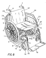
- Fig. 8 is a perspective view of the wheel-chair according to the invention completed with the seat 1 and the back 32 made of fabric and with side boards 23 with arm-rests 24.
- Numeral 2 denotes the front riser that, with the iron girders 4' and 10 and the rear riser 2' (not shown), compose the basic structure; 3-8-9 denote the members composing the cross connecting the two side frames.
- Numeral 5 denotes the wheel and numeral 6 denotes the driving ring integral therewith; 4 denotes the stakes supporting the back 32 and 7 denotes the handles to drive the wheel-chair by third parties.
- Numeral 18 denotes the support for the swingable fork 13 of the small wheel 14; 15 denotes the bracket supporting the rod 20 supporting in turn the foot-rest 19; 29 denotes the lever controlling the stake to block the bracket 15 to the riser 2; 26 denotes the stake with which the caliper 31 connected to the lever 28 comes to be engaged; 11 denotes the braking apparatus to block the wheel 5.
- the features of the invention stand out, that is, it is possible to manufacture a wheel-chair without intervening with heat seals, but instead assembling prefabricated parts, some of which are of the modular type (such as risers (2', 2) and iron girders 10 and 4') using only screws and rivets.
- the parts composing the wheel-chair are not necessarily metallic ones, being able to be obtained with particular resinous materials, in which case couplings can also be carried out by glueing.
- the basic structure is realized in such a way as to be completed without problems with some parts more than others depending on the application provided for the wheel-chair, interchangeability having been provided.
- the novel modular parts include assembly of the brackets 15 supporting the rods for the foot-rest, with the front risers 2.
Abstract
Description
- The present invention deals with wheel-chairs for disabled people, and in particular with a wheel-chair for disabled people adapted to be reduced and obtained by assembling single parts, some of them being modular, without requiring heat seals.
- The subject dealing with wheel-chairs for disabled people is well known to skilled people in the field and is particularly taken care of by people interested in purchasing the item. Manufacturers have marketed several types of wheel-chairs, having different performances, to satisfy the complex needs of disabled people that have to use them.
- For all kinds of solutions two aspects are of paramount importance: cost and performances.
- It is obvious that all wheel-chairs must have a seat, a back and wheels. There could be upon request: handles to push and drive the wheel-chair by the person assisting the disabled; side boards with or without armrest; foot-resting boards; etc.
- EP 0 702 945 illustrates a wheelchair with two facing, interconnected, adjustable sideframes having fit thereto a seat, backrest, driving wheels and guide wheels. Each sideframe has two rigid frame parts, which are adjustably interconnected in the longitudinal direction of the wheelchair by elongated frame sections. Simultaneously with the adjustment of the seat position, there is an adjustment of the wheels so that an optimum weight distribution over the wheelchair wheels is maintained.
- US 5 284 350 refers to a foldable wheelchair having a folding mechanism connecting two side frame assemblies to each other. The side frame assemblies are made of two halves that are secured together and may be fabricated from compression or injection molded composite plastics. The seat angle is adjusted by pivoting the side frame assemblies around a pivot point located in an upward and forward region of the side frame assembly.
- Purpose of the present invention is manufacturing at a competitive price wheel-chairs equipped with parts facilitating their use.
- This purpose is obtained by revolutioning the currently used system. The wheel-chair is not obtained any more by sealing a certain number of members one to the other, but assembling without sealing single component parts of the prefabricated type. These component parts too are obtained without seals. This is very important because thereby the different component parts can also be non-metallic. Complementary parts being required are assembled to the basic skeleton, obtained by assembling modular parts without sealing. By adequately choosing said complementary parts, wheel-chairs are obtained that can provide different performance or comfort.
- Assembly of the different parts is carried out with screws or rivets; but it could also be carried out by glueing, taking into account that said parts to be assembled can also be non-metallic. The chance of putting together single parts to be chosen among a plurality thereof depending on market needs generates savings both when manufacturing the parts and when storing them.
- The above and other purposes and advantages of the present invention will be better understood by reference to the following drawings, in which:
- Fig. 1 schematically represents and summarizes a wheel-chair for disabled people adapted to be reduced;
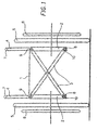
- Fig. 2 schematically shows a wheel-chair side frame according to the invention;
- Fig. 3 is a view of the side frame shown in Fig. 2;
- Fig. 4 is a view of a shelf to be used with the present invention;
- Fig. 5 shows a coupling condition between the shelf in Fig. 4 and a riser;
- Fig. 6 shows another coupling condition between shelf and riser;
- Fig. 7 shows the shelf separated from the riser; and
- Fig. 8 is a perspective view of the wheel-chair according to the invention.
-
- With reference to Fig. 1, numeral 1 denotes a seat made of tissue with two
side frames 2; 3 denotes the cross rods that keep theside frames 2 parallel and defines the maximum opening thereof; 4 denotes the stakes to hold the sheet composing the back and whose extension over the back creates handles 7 to make third parties drive the wheel-chair; 5 denotes the wheels; 6 the rings integral with the wheels for possible handling of the wheel-chair by the user; 8 denotes the lower side frame cross members; 10 denotes the iron girders applied to lower ends of therods rods 3. - With reference to Fig. 2,
cross rods 3 have not been included in the drawing for reasons of clarity. - The basic structure is composed of a quadrilateral formed of box-
type risers 2' and 2 andcylinder iron girders 4' and 10.Numeral 8 denotes the tubular cross member integral with the lower ends of thecross rods 3 suitable to rotate around thesupport iron girders 10 to which it is coupled; 9 denotes the cross member integral with the upper ends of thecross rods 3 and on which the seat made of fabric is applied; 4 denotes the stake operating as support for the back made of fabric and that extends upwards to realize the driving handle 7; 5 denotes the wheel integral with thedriving ring 6. Thesupport 18 is secured into the lower part of theriser 2 for theswingable fork 13 of thesmall wheel 14 and in the upper part of said riser thebraking device 11 is secured to brake thewheel 5. Theriser 2 is equipped with ashelf 15 supporting arod 16 that can be blocked in the desired position. Coupling betweenshelf 15 andriser 2 is realized in such a way as to allow an easy assembly and as easy a separation. Thebracket 17 is integral with therod 16. Therod 20 is hinged onto thebracket 17 and supports the foot-rest 19. - With reference to Fig. 3, the equipment related to foot-rest has been modified and the arm-
rest 24 appears equipped with awall 23. The above-said arm-rest 24 withrelated wall 23, once released from the closure applied in 26, can be lifted backwards by rotating around thehinging point 25.Numerals 2' and 2 denote risers that, with theiron girders 10 and 4', compose the basic structure; 5 denotes the wheel; 6 denotes the driving ring integral with thewheel 5; 8 and 9 denote tubular longitudinal members applied to the ends ofcross rods 3; 18 denotes the support secured to theriser 2 for theswingable fork 13 of thesmall wheel 14; 15 denotes the bracket secured to theriser 2 supporting therod 20 supporting in turn the foot-rest 10; 11 denotes the braking apparatus for thewheel 5. - Fig 4 shows how the
bracket 15 is coupled with theriser 2. Numeral 21 denotes a cylindrical post with two facetings belonging to theriser 2, coupled with theseat 27 for thebracket 15. Coupling is made possible when the opening 30 for theseat 27 is placed next to the lower width of thepost 21. Once having inserted thepost 21 into theseat 27, by rotating thebracket 15 the coupling becomes a constraint. Numeral 20 denotes the rod supporting the foot-rest. - Fig, 5 show in particular the coupling between
bracket 15 andriser 2. In this view, the shelf is blocked by a stake connected to thelever 29. To release it, it is necessary to lift thelever 29 and rotate thebracket 15 outwards. Numerals 4' and 10 denote the iron girders that with therisers 2' and 2 compose the basic structure; 9 denote the longitudinal member located on the upper end of thecross rods 3; 24 denotes the lower end part of the arm-rest that is blocked by a bolt 28-31 on thestake 26; 11 denotes the braking apparatus for the wheel; 18 denotes the support, secured to theriser 2, for theswingable fork 13 of thesmall wheel 14. - Fig. 6 shows the
bracket 15 rotated outwards with respect to theriser 2. The opening 30 for theseat 27 is placed next to the lower width of the facetedpost 21, ready to be disengaged. An identical position of the opening 30 of thebracket 15 with respect to thepost 21 occurs when assembling the brackets on theriser 2. Insertion and removal of the bracket on theriser 2 are, in fact, carried out with the same methods. Numeral 20 denotes the rod held by the shelf; bracket; 19 denotes the foot-rest secured to the lower end of therod 20; 18 denotes the support, secured to theriser 2, of theswingable fork 13 of thesmall wheel 14; 9 denotes the longitudinal member placed on the upper end of thecross rod 3; 24 denotes the lower end part of the arm-rest that is blocked by the bolt 28-31 on thestake 26; 11 denotes the braking apparatus of the wheel. - Fig. 7 shows the
bracket 15 separated from theriser 2. The opening 30 of theseat 27 of thebracket 15 and thepost 21 with one of the two facetings visible, are shown. Numeral 3 denotes the cross roads; 8 denotes the longitudinal member joined to the lower end thereof; 10 denotes the iron girder of the basic structure; 29 denotes the lever operating the stake to block thebracket 15; 20 denotes the rods held by thebracket 15; 18 denotes the support for theswingable fork 13 of thesmall wheel 14 secured to theriser 2. - Fig. 8 is a perspective view of the wheel-chair according to the invention completed with the seat 1 and the
back 32 made of fabric and withside boards 23 with arm-rests 24. Numeral 2 denotes the front riser that, with theiron girders 4' and 10 and the rear riser 2' (not shown), compose the basic structure; 3-8-9 denote the members composing the cross connecting the two side frames. Numeral 5 denotes the wheel andnumeral 6 denotes the driving ring integral therewith; 4 denotes the stakes supporting theback 32 and 7 denotes the handles to drive the wheel-chair by third parties. Numeral 18 denotes the support for theswingable fork 13 of thesmall wheel 14; 15 denotes the bracket supporting therod 20 supporting in turn the foot-rest 19; 29 denotes the lever controlling the stake to block thebracket 15 to theriser 2; 26 denotes the stake with which thecaliper 31 connected to thelever 28 comes to be engaged; 11 denotes the braking apparatus to block thewheel 5. - From what has been previously stated and shown by the drawings, the features of the invention stand out, that is, it is possible to manufacture a wheel-chair without intervening with heat seals, but instead assembling prefabricated parts, some of which are of the modular type (such as risers (2', 2) and
iron girders 10 and 4') using only screws and rivets. The parts composing the wheel-chair are not necessarily metallic ones, being able to be obtained with particular resinous materials, in which case couplings can also be carried out by glueing. - The basic structure is realized in such a way as to be completed without problems with some parts more than others depending on the application provided for the wheel-chair, interchangeability having been provided. Particularly; the novel modular parts include assembly of the
brackets 15 supporting the rods for the foot-rest, with thefront risers 2. - Embodiments exploiting the innovative concept of the present invention remain within the scope thereof. Shapes and sizes for the single parts, and nature of the materials used are not intended to limit the scope of the present invention as defined in the following claims.
Claims (9)
- Wheel-chair for disabled people adapted to be reduced and obtained by assembling single parts, some of them being modular, without requiring heat seals, comprising:characterised in that said front risers (2) each comprise a cylindrical post (21) having a pair of opposed flat faces which are parallel and define therebetween a width less than the diameter of the cylindrical post (21), and in that said brackets (15) each include a seat (27) comprising an opening (30) having a width narrower than the diameter of the cylindrical post (21) and wider than the width of the post between the opposed flat faces, and said seat (27) having a diameter corresponding to the diameter of the post (21), such that said post (21) can be inserted into said seat (27) when the opening (30) is aligned with the width of the post defined between the opposed flat faces and then rotated to lock the bracket (15) to said post (21), whereby coupling/uncoupling of the foot-rest boards with respect to the wheel-chair is made possible by solely rotating the brackets (15) inwards/outwards without the need of any vertical movement of the brackets.two side frames, each one being composed of a basic structure formed by front (2) and rear (2') box-type risers and two iron girders (4', 10) joined together through screws and/or rivets;one scissors-shaped articulated cross including rods (3) that are hinged together, said rods (3) being integral with tubular longitudinal members (8, 9) at the upper and lower ends thereof;two brackets (15) supported by said front risers (2) supporting rods (20) whose lower ends are equipped with foot-rest boards (19), said shelves (15) being movable and separable from said risers (2);two stakes (4) applied to said rear risers (2') to support a back (32);two side boards (23);two pairs of front and rear wheels (5, 14);two devices (11) to brake said wheels (5),
- Wheel-chair for disabled people according to claim 1, characterised in that said stakes (4) applied to said rear risers (2') projects above said back (32) for providing handles (7) for driving by third parties.
- Wheel-chair for disabled people according to claim 1, characterised in that said side boards (23) are provided with arm-rests (24) which are hinged to said rear-risers (2') and adapted to be blocked onto said front risers (2), being it possible to lift or remove them.
- Wheel-chair for disabled people according to claim 1, characterised in that said rear wheels (5) are equipped with rings (6) integral therewith to make a user drive said wheel-chair.
- Wheel-chair for disabled people according to claim 1, characterised in that said cross (3) is assembled to said side frames by engaging through a swingable coupling its own lower tubular longitudinal members (8) with the lower iron girders (10) of the side frame; and by connecting its own rods (3) with the upper iron girders (4') of the side frames through connection means.
- Wheel-chair for disabled people according to claim 1, characterised in that said front risers (2) are provided with a stopper stake connected to a corresponding lever (29) which can be operated manually, said stake being for blocking the brackets (15) in the corresponding front riser after said brackets (15) are rotated inwards.
- Wheel-chair for disabled people according to claim 1, characterised in that said side frames and brackets are made of non metallic material.
- Wheel-chair for disabled people according to claim 8, characterised in that said side frames and brackets are made of resinous material.
- Wheel-chair for disabled people according to any of the previous claims, characterized in that all parts composing said wheel-chair are assembled without any heat seal but only through screws and/or rivets or viceversa, this being valid both for parts composing said basic structure and for complementary parts.
Applications Claiming Priority (2)
| Application Number | Priority Date | Filing Date | Title |
|---|---|---|---|
| ITPD960124 | 1996-05-17 | ||
| IT96PD000124A IT1287901B1 (en) | 1996-05-17 | 1996-05-17 | WHEELCHAIR FOR THE DISABLED, OF THE REDUCIBLE TYPE, WHICH CAN BE OBTAINED BY THE ASSEMBLY OF THE SINGLE PARTS, OF WHICH SOME MODULAR, WITHOUT |
Publications (3)
| Publication Number | Publication Date |
|---|---|
| EP0807427A2 EP0807427A2 (en) | 1997-11-19 |
| EP0807427A3 EP0807427A3 (en) | 1997-12-03 |
| EP0807427B1 true EP0807427B1 (en) | 2003-03-12 |
Family
ID=11391427
Family Applications (1)
| Application Number | Title | Priority Date | Filing Date |
|---|---|---|---|
| EP97106524A Expired - Lifetime EP0807427B1 (en) | 1996-05-17 | 1997-04-20 | Modular wheelchair |
Country Status (7)
| Country | Link |
|---|---|
| US (1) | US6126187A (en) |
| EP (1) | EP0807427B1 (en) |
| AT (1) | ATE234062T1 (en) |
| CA (1) | CA2205319A1 (en) |
| DE (1) | DE69719594T2 (en) |
| ES (1) | ES2195047T3 (en) |
| IT (1) | IT1287901B1 (en) |
Families Citing this family (3)
| Publication number | Priority date | Publication date | Assignee | Title |
|---|---|---|---|---|
| US6774100B2 (en) * | 2000-12-06 | 2004-08-10 | Imaginative Research Associates, Inc. | Anhydrous creams, lotions and gels |
| US8622409B2 (en) | 2009-03-03 | 2014-01-07 | Melvin G. Hector, JR. | Structure, components and method for constructing and operating an automatically self locking manually propelled vehicle such as a wheel chair |
| CA3075580C (en) | 2011-11-27 | 2021-10-26 | Stryker Corporation | Wheeled chair |
Family Cites Families (15)
| Publication number | Priority date | Publication date | Assignee | Title |
|---|---|---|---|---|
| US3185527A (en) * | 1963-11-14 | 1965-05-25 | Mobilaid Inc | Swinging foot rest |
| US3453027A (en) * | 1966-10-31 | 1969-07-01 | Mobilaid Inc | Latch for swinging footrest |
| US3854774A (en) * | 1973-08-06 | 1974-12-17 | Gendron Diemer Inc | Swing-away footrest for invalid wheelchairs |
| US4120532A (en) * | 1977-08-01 | 1978-10-17 | Clanan Wayne N | Snap-on swing-away foot rest for wheel chairs |
| US4176879A (en) * | 1978-07-31 | 1979-12-04 | Everest & Jennings, Inc. | Wheelchair foot rest latch |
| JPS5919128U (en) * | 1982-07-29 | 1984-02-06 | 工業技術院長 | wheelchair |
| GB8330289D0 (en) * | 1983-11-14 | 1983-12-21 | Lieuse Techn Ltd | Wheelchair |
| DE3514572A1 (en) * | 1985-04-23 | 1986-10-30 | Günter Meier GmbH, 4952 Porta Westfalica | MEDICAL ELEVATOR |
| GB2200328B (en) * | 1987-01-28 | 1991-05-15 | Spastics Soc | Lightweight foldable wheelchair |
| US5186480A (en) * | 1990-12-05 | 1993-02-16 | Morgan Technology, Inc. | Lightweight transportable wheelchair |
| US5360224A (en) * | 1991-11-08 | 1994-11-01 | Medical Composite Technology, Inc. | Wheelchair frame assembly and components for use thereon |
| US5284350A (en) * | 1992-05-22 | 1994-02-08 | Medical Composite Technology | Foldable wheelchair and side frame assembly |
| US5560627A (en) * | 1993-11-16 | 1996-10-01 | Guardian Products, Inc. | Low cost wheelchair |
| US5333887A (en) * | 1993-11-16 | 1994-08-02 | Joe Sharp | Wheelchair/gurney |
| US5516226A (en) * | 1994-08-30 | 1996-05-14 | Wu; Johnson | Wheelchair frame assembly |
-
1996
- 1996-05-17 IT IT96PD000124A patent/IT1287901B1/en active IP Right Grant
-
1997
- 1997-04-20 ES ES97106524T patent/ES2195047T3/en not_active Expired - Lifetime
- 1997-04-20 AT AT97106524T patent/ATE234062T1/en not_active IP Right Cessation
- 1997-04-20 EP EP97106524A patent/EP0807427B1/en not_active Expired - Lifetime
- 1997-04-20 DE DE69719594T patent/DE69719594T2/en not_active Expired - Lifetime
- 1997-04-23 US US08/844,972 patent/US6126187A/en not_active Expired - Lifetime
- 1997-05-14 CA CA002205319A patent/CA2205319A1/en not_active Abandoned
Also Published As
| Publication number | Publication date |
|---|---|
| DE69719594D1 (en) | 2003-04-17 |
| EP0807427A2 (en) | 1997-11-19 |
| CA2205319A1 (en) | 1997-11-17 |
| ES2195047T3 (en) | 2003-12-01 |
| ITPD960124A1 (en) | 1997-11-17 |
| ATE234062T1 (en) | 2003-03-15 |
| US6126187A (en) | 2000-10-03 |
| DE69719594T2 (en) | 2004-03-11 |
| ITPD960124A0 (en) | 1996-05-17 |
| IT1287901B1 (en) | 1998-08-26 |
| EP0807427A3 (en) | 1997-12-03 |
Similar Documents
| Publication | Publication Date | Title |
|---|---|---|
| US5480179A (en) | Wheelchair chassis | |
| KR100333767B1 (en) | Collapsible wheelchair | |
| US4981305A (en) | Symmetrically modular wheelchair | |
| EP0145278B1 (en) | Wheelchair | |
| US5253888A (en) | Rigid frame weldless wheelchair | |
| EP0329002A2 (en) | Reclinable wheelchair | |
| US6464243B2 (en) | Wheel chair | |
| US4736960A (en) | Folding wheelchairs | |
| US20040084230A1 (en) | Transportable wheelchair | |
| US20040155429A1 (en) | Wheelchair and wheel mounting assembly therefore | |
| MXPA06008422A (en) | Collapsible conveyance folding transport chair folding wheelchair. | |
| US8622409B2 (en) | Structure, components and method for constructing and operating an automatically self locking manually propelled vehicle such as a wheel chair | |
| US4457535A (en) | Wheelchair | |
| WO1999039676A1 (en) | Seat back recliner kit for wheelchair | |
| US3833256A (en) | Folding foot rest and brace for folding wheelchairs | |
| WO1989004622A1 (en) | Lightweight wheelchair having swing-away footrest assembly | |
| EP1056635B1 (en) | Wheelchair and link assembly for use with a wheelchair | |
| EP0807427B1 (en) | Modular wheelchair | |
| CN215779274U (en) | Foldable support connecting frame and wheelchair using same | |
| HU213422B (en) | Wheal-chair | |
| EP0942703B1 (en) | A wheelchair | |
| AU661936B2 (en) | Improvements in, or relating to wheelchairs | |
| CA2096459C (en) | Collapsible wheelchair | |
| GB2268134A (en) | Shopping trolley for use with wheelchair. | |
| JPH0345706Y2 (en) |
Legal Events
| Date | Code | Title | Description |
|---|---|---|---|
| PUAI | Public reference made under article 153(3) epc to a published international application that has entered the european phase |
Free format text: ORIGINAL CODE: 0009012 |
|
| PUAL | Search report despatched |
Free format text: ORIGINAL CODE: 0009013 |
|
| AK | Designated contracting states |
Kind code of ref document: A2 Designated state(s): AT BE CH DE ES FR GB GR IT LI SE |
|
| AK | Designated contracting states |
Kind code of ref document: A3 Designated state(s): AT BE CH DE ES FR GB GR IT LI SE |
|
| TPAD | Observations filed by third parties |
Free format text: ORIGINAL CODE: EPIDOS TIPA |
|
| 17P | Request for examination filed |
Effective date: 19980325 |
|
| 17Q | First examination report despatched |
Effective date: 20010330 |
|
| GRAG | Despatch of communication of intention to grant |
Free format text: ORIGINAL CODE: EPIDOS AGRA |
|
| GRAG | Despatch of communication of intention to grant |
Free format text: ORIGINAL CODE: EPIDOS AGRA |
|
| GRAH | Despatch of communication of intention to grant a patent |
Free format text: ORIGINAL CODE: EPIDOS IGRA |
|
| GRAH | Despatch of communication of intention to grant a patent |
Free format text: ORIGINAL CODE: EPIDOS IGRA |
|
| GRAA | (expected) grant |
Free format text: ORIGINAL CODE: 0009210 |
|
| AK | Designated contracting states |
Designated state(s): AT BE CH DE ES FR GB GR IT LI SE |
|
| REG | Reference to a national code |
Ref country code: GB Ref legal event code: FG4D |
|
| REG | Reference to a national code |
Ref country code: CH Ref legal event code: EP |
|
| REF | Corresponds to: |
Ref document number: 69719594 Country of ref document: DE Date of ref document: 20030417 Kind code of ref document: P |
|
| REG | Reference to a national code |
Ref country code: CH Ref legal event code: NV Representative=s name: KEMIA S.A. |
|
| REG | Reference to a national code |
Ref country code: SE Ref legal event code: TRGR |
|
| REG | Reference to a national code |
Ref country code: GR Ref legal event code: EP Ref document number: 20030402041 Country of ref document: GR |
|
| ET | Fr: translation filed | ||
| PLBE | No opposition filed within time limit |
Free format text: ORIGINAL CODE: 0009261 |
|
| STAA | Information on the status of an ep patent application or granted ep patent |
Free format text: STATUS: NO OPPOSITION FILED WITHIN TIME LIMIT |
|
| 26N | No opposition filed |
Effective date: 20031215 |
|
| REG | Reference to a national code |
Ref country code: CH Ref legal event code: PFA Owner name: VASSILLI S.R.L. Free format text: VASSILLI S.R.L.#VIA IRPINIA 1-3 - Z.A.I.#35020 SAONARA (PADOVA) (IT) -TRANSFER TO- VASSILLI S.R.L.#VIA IRPINIA 1-3 - Z.A.I.#35020 SAONARA (PADOVA) (IT) |
|
| PGFP | Annual fee paid to national office [announced via postgrant information from national office to epo] |
Ref country code: CH Payment date: 20100325 Year of fee payment: 14 |
|
| PGFP | Annual fee paid to national office [announced via postgrant information from national office to epo] |
Ref country code: GB Payment date: 20100322 Year of fee payment: 14 |
|
| PGFP | Annual fee paid to national office [announced via postgrant information from national office to epo] |
Ref country code: BE Payment date: 20100324 Year of fee payment: 14 Ref country code: AT Payment date: 20100324 Year of fee payment: 14 |
|
| PGFP | Annual fee paid to national office [announced via postgrant information from national office to epo] |
Ref country code: SE Payment date: 20100324 Year of fee payment: 14 |
|
| PGFP | Annual fee paid to national office [announced via postgrant information from national office to epo] |
Ref country code: GR Payment date: 20100326 Year of fee payment: 14 |
|
| BERE | Be: lapsed |
Owner name: *VASSILLI S.R.L. Effective date: 20110430 |
|
| REG | Reference to a national code |
Ref country code: SE Ref legal event code: EUG |
|
| REG | Reference to a national code |
Ref country code: CH Ref legal event code: PL |
|
| GBPC | Gb: european patent ceased through non-payment of renewal fee |
Effective date: 20110420 |
|
| REG | Reference to a national code |
Ref country code: AT Ref legal event code: MM01 Ref document number: 234062 Country of ref document: AT Kind code of ref document: T Effective date: 20110420 |
|
| REG | Reference to a national code |
Ref country code: GR Ref legal event code: ML Ref document number: 20030402041 Country of ref document: GR Effective date: 20111102 |
|
| PG25 | Lapsed in a contracting state [announced via postgrant information from national office to epo] |
Ref country code: CH Free format text: LAPSE BECAUSE OF NON-PAYMENT OF DUE FEES Effective date: 20110430 Ref country code: BE Free format text: LAPSE BECAUSE OF NON-PAYMENT OF DUE FEES Effective date: 20110430 Ref country code: LI Free format text: LAPSE BECAUSE OF NON-PAYMENT OF DUE FEES Effective date: 20110430 |
|
| PG25 | Lapsed in a contracting state [announced via postgrant information from national office to epo] |
Ref country code: AT Free format text: LAPSE BECAUSE OF NON-PAYMENT OF DUE FEES Effective date: 20110420 Ref country code: GB Free format text: LAPSE BECAUSE OF NON-PAYMENT OF DUE FEES Effective date: 20110420 Ref country code: GR Free format text: LAPSE BECAUSE OF NON-PAYMENT OF DUE FEES Effective date: 20111102 |
|
| PG25 | Lapsed in a contracting state [announced via postgrant information from national office to epo] |
Ref country code: SE Free format text: LAPSE BECAUSE OF NON-PAYMENT OF DUE FEES Effective date: 20110421 |
|
| PGFP | Annual fee paid to national office [announced via postgrant information from national office to epo] |
Ref country code: DE Payment date: 20140411 Year of fee payment: 18 Ref country code: IT Payment date: 20140409 Year of fee payment: 18 Ref country code: ES Payment date: 20140411 Year of fee payment: 18 |
|
| PGFP | Annual fee paid to national office [announced via postgrant information from national office to epo] |
Ref country code: FR Payment date: 20140411 Year of fee payment: 18 |
|
| REG | Reference to a national code |
Ref country code: DE Ref legal event code: R119 Ref document number: 69719594 Country of ref document: DE |
|
| PG25 | Lapsed in a contracting state [announced via postgrant information from national office to epo] |
Ref country code: DE Free format text: LAPSE BECAUSE OF NON-PAYMENT OF DUE FEES Effective date: 20151103 Ref country code: IT Free format text: LAPSE BECAUSE OF NON-PAYMENT OF DUE FEES Effective date: 20150420 |
|
| REG | Reference to a national code |
Ref country code: FR Ref legal event code: ST Effective date: 20151231 |
|
| PG25 | Lapsed in a contracting state [announced via postgrant information from national office to epo] |
Ref country code: FR Free format text: LAPSE BECAUSE OF NON-PAYMENT OF DUE FEES Effective date: 20150430 |
|
| REG | Reference to a national code |
Ref country code: ES Ref legal event code: FD2A Effective date: 20160526 |
|
| PG25 | Lapsed in a contracting state [announced via postgrant information from national office to epo] |
Ref country code: ES Free format text: LAPSE BECAUSE OF NON-PAYMENT OF DUE FEES Effective date: 20150421 |