EP0807311B1 - Device for voltage control - Google Patents
Device for voltage control Download PDFInfo
- Publication number
- EP0807311B1 EP0807311B1 EP96902973A EP96902973A EP0807311B1 EP 0807311 B1 EP0807311 B1 EP 0807311B1 EP 96902973 A EP96902973 A EP 96902973A EP 96902973 A EP96902973 A EP 96902973A EP 0807311 B1 EP0807311 B1 EP 0807311B1
- Authority
- EP
- European Patent Office
- Prior art keywords
- voltage
- switching element
- section
- turns
- transformer
- Prior art date
- Legal status (The legal status is an assumption and is not a legal conclusion. Google has not performed a legal analysis and makes no representation as to the accuracy of the status listed.)
- Expired - Lifetime
Links
Images


Classifications
-
- H—ELECTRICITY
- H01—ELECTRIC ELEMENTS
- H01F—MAGNETS; INDUCTANCES; TRANSFORMERS; SELECTION OF MATERIALS FOR THEIR MAGNETIC PROPERTIES
- H01F30/00—Fixed transformers not covered by group H01F19/00
- H01F30/02—Auto-transformers
-
- H—ELECTRICITY
- H01—ELECTRIC ELEMENTS
- H01F—MAGNETS; INDUCTANCES; TRANSFORMERS; SELECTION OF MATERIALS FOR THEIR MAGNETIC PROPERTIES
- H01F29/00—Variable transformers or inductances not covered by group H01F21/00
- H01F29/02—Variable transformers or inductances not covered by group H01F21/00 with tappings on coil or winding; with provision for rearrangement or interconnection of windings
Definitions
- the invention relates to a lighting system with gas discharge lamps and an autotransformer uninterrupted voltage regulation of the Gas discharge lamps.
- a street lighting system will be used during the evening rush hour generally with full Luminous intensity, i.e. operated with mains voltage, and in the quiet night time with reduced tension. With gas discharge lamps, switching from the Mains voltage to the reduced voltage and vice versa uninterrupted, otherwise the lamp will fail.
- this is stepless adjustable transformers used, e.g. B. a Autotransformer that has an iron core with only one Has winding, the input side with the phase of Network and the neutral conductor and on the output side with one Tapping the transformer winding and the neutral conductor connected is.
- the voltage to be removed is indicated by Tap the line leading to the phase of the consumer leads, obtained on a turn of the winding.
- the Ratio of the voltage to be reduced to the nominal voltage corresponds to the ratio of the number of turns, between the output side of the winding and of the stripped turn to the total number the winding of the winding.
- the entire winding forms so the primary winding, during the winding section between the tap and the neutral Secondary winding of the savings transformer forms.
- Designated load section is also called Designated load section.
- variable transformers are known in which the Winding is provided with taps. So while there is no interruption of switching and no short circuit of the turns to be switched on and off occurs in each branch between tapping and the supply line to the consumer two switching elements provided, the second switching element a Resistance bridged. The switching process begins with the fact that in the connected, first branch of the Resistor is turned on and then over an equal resistance in the other branch Connection is made with the new tap. The turns to be switched between the two Taps are now short-circuited in the Short circuit, however, are the two resistors and limit the short-circuit current. If so now first switching element is separated in the first branch, the new tap is already connected. Your direct connection to the outer supply line finally by closing the second switching element in the second branch reached.
- the well-known variable transformer with tap changer is through the two switching elements and the resistance at each tap is expensive and accordingly expensive.
- the object of the invention is a simple structure To provide lighting system with gas discharge lamps, which is an uninterrupted voltage regulation of gas discharge lamps.
- the device according to the invention is preferably used for Bridging the load section of the transformer and the other switching element, the primary winding except To put operation. It can also be in the control section be provided.
- the two Switching elements When switching to change the Voltage on the gas discharge lamps are the two Switching elements controlled so that the load section Throttle forms. In this way, the Gas discharge lamps when switching always with the Minimum voltage supplied. When switching between individual switching elements practically simultaneously takes place, the throttling effect can hardly bear come. The short circuit can then be so short that the short-circuit current cannot increase.
- the Switching elements can therefore be controlled so that a Short circuit is limited in time so that a Damage to the switching elements or lines is prevented.
- controllable transformer there is the primary and / or Secondary winding preferably at least partly from individual sections, which in one of the combination corresponding to decreasing voltage are interconnectable.
- At least one section has the first switching element in its current path and the other between its entrance and the exit Switching element on.
- the switching elements are preferred by Sagittarius formed.
- Each section can have one Resistor, a choke and / or a fuse have, preferably a line with the one Switching element is provided with which the consumer the phase of the network can be connected.
- the further Switching element can be arranged in the line, which the load section on the output side with the consumer connects.
- the transformer winding of the autotransformer has preferably one on the input side to the phase of Network and output side to the phase of the consumer connected load section and one connected on the output side to the neutral conductor Control section on, which at least partially from the Individual sections that exist in one of the combination with decreasing voltage the neutral are connectable.
- the tax section consists preferably of a first part and a second part. The second part is between the arranged first part and the load section. It is the number of turns connected to the neutral conductor of the second part unchangeable, while the number of turns of the first which can be connected to the neutral conductor Is partly changeable.
- the consumer is one Lighting system with gas discharge lamps.
- the gas discharge lamps at full light intensity So operating with mains voltage is the first Switching element closed and the second switching element open. If the Brightness reduced, that is Gear ratio of the transformer corresponding voltage drop, the first switching element opened and the second switching element getting closed. To do this is a certain one Switchover time necessary.
- the two switching elements are preferably by protection with make contacts and / or protection with make and break contacts. At protection as a switching element is the switchover time a few milliseconds.
- a switching element in the primary circuit opened So that goes the load section of the transformer, i.e. the Section over which the load current flows into a Throttle over. This way a failure of the Lamp prevented during the switching process. Then the further switching element is closed, whereby a the transformation ratio of the transformer sets the corresponding voltage drop.
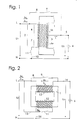
- FIGS. 1 to 5 a different circuit of an autotransformer show according to the invention.
- the autotransformer consists of a closed iron core 1 with a winding 2. Die entire winding 2 forms the primary winding of the Autotransformer, section 4 of winding 2 between phase L of the network and tap 3 of the Line 5 to the gas discharge lamp 6 provides the The load section represents the load current IL to the lamp 6 flows.
- the winding section 7 between the tap 3 and the neutral conductor N forms the secondary winding of the Autotransformer through which the magnetizing current IM and a compensation current dependent on the load flows.
- the phase L of the network is via a bypass line 8 connected to line 5.
- the bypass line 8 has a first switching element 9, so that they at closed switching element 9 the load section 4th bridged.
- the output of the secondary winding 7 is with the neutral conductor N connected via a line 10, the one has second switching element 11.
- the two switching elements 9 and 11 are by a Contactor, i.e. a remote-controlled electromagnetic Switch formed, preferably by the closer or opener of the same contactor, or by the two NO contacts of a contactor, as in the drawing shown.
- a Contactor i.e. a remote-controlled electromagnetic Switch formed, preferably by the closer or opener of the same contactor, or by the two NO contacts of a contactor, as in the drawing shown.
- the nominal voltage is designated U1, and the Load voltage with U2.
- the switching element 9 opens and the switching element 11 is closed, that is at unactuated contactor, the lamp 6 with the by Transformer reduced voltage U2 ⁇ U1 operated.
- the contactor is actuated.
- the load section 4 acts during the switching time of Protection for a short time, d. H. for example 5 to 50 Milliseconds as a choke.
- the throttle leads to a voltage drop. However, this is low, so that the lamp 6 during the switching process with a sufficient voltage U2 is supplied.
- closes the switching element 9, whereby the load section 4th or bridged the choke and thus the lamp 6 with the nominal voltage U1 is operated, that is U2 U1.
- the nominal voltage z. B. is 220 V
- the reduced voltage U2 is greater is than that for operating the gas discharge lamp 6 required minimum voltage, preferably 5 V to 10 V greater than the minimum voltage to accommodate fluctuations in the Nominal voltage.
- the load section 4 is the Bridged transformer and the primary winding 2 or the control section 7 is deactivated.
- the two switching elements 9, 11 are each so controlled that the load section 4 a Gas discharge lamps 6 forms upstream choke.
- FIG. 2 shows a transformer with a primary winding 12 and a secondary winding 13 on a closed one Iron core 1 shown. Through lines 15 and 16 this transformer is also switched as an economy transformer.
- the secondary winding 13 forms the load section of the Transformer, i.e. the section over which the Load current IL flows via line 14 to lamp 6.
- the secondary winding 13 has a bypass line 8 can be bridged with a first switching element 9.
- the primary winding 12 is on the input side with the phase L of the network connected via a line 15 in which the second switching element 11 is arranged.
- the exit side the primary winding 12 is connected via a line 16 to the Neutral conductor N connected.
- the switching element 9 When the load voltage U2 to a reduced voltage U2 ⁇ U1 is to be switched, the switching element 9 first opened so that the secondary winding 13 as Throttle acts, whereupon the switching element 11 is closed becomes.
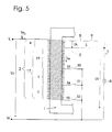
- FIG. 1 An autotransformer is shown in FIG which the load voltage U2 can be finely regulated can.
- the secondary winding 7 of Figure 1 is there replaced by a control section 17.
- the control section 17 is composed of a first part 18 and a second part 19 is formed.
- the turns of the second part 19 connect to the turns of the Load section 4.
- the turns of the first part 18 the control section 17 consist of several Sections I to IV.
- Each individual section I to IV points in its current path a first switching element 24 to 27. Furthermore, a Switching element 28 to 31 between the input side E and the output side A of each section I to IV intended. From the input side E each Section I to IV leads a line 32 to 35 to the turns of the relevant section I to IV, with the first in lines 32 to 35 Switching element 24 to 27 is arranged. Another Line 36 to 39 leads from the turns of the each individual section I to IV to the Output side A of the same.
- the input side E of the first individual section I is via a line 40 to the output side of the second Part 19 of the control section 17 connected while the output side A of the facing away from the second part 19 Section IV via a line 41 with the Neutral conductor N is connected, in line 41 that Switching element 11 is arranged.
- a line 40 to the output side of the second Part 19 of the control section 17 connected while the output side A of the facing away from the second part 19 Section IV via a line 41 with the Neutral conductor N is connected, in line 41 that Switching element 11 is arranged.
- the Switching elements 28 to 31 are the Switching elements 28 to 31.
- Each individual section I to IV has one different number of turns. For example, can the individual section I ten, the individual section II twenty, section III forty and the Individual section IV have eighty turns.
- the number of turns NM of the Control section 17, which is connected to the neutral conductor are in accordance with the voltage U2 to be taken be changed.
- the number of turns NM of the The control section consists of the unchangeable Number of turns NM const. Of the second part 19 and changeable number of turns NM v of the individual sections I to IV, which are connected to the neutral conductor N.
- the voltage to be decreased U2 for all connected four individual sections I to IV z. B. 210 V and the decreasing voltage U2 for all four switched off Individual sections I to IV, i.e. only with the turns of the second part 19 of the control section 17 z. B. 170 V the voltage U2 can be between 170 V and 210 V can be changed in sixteen steps.
- the change in voltage at each stage is but not the same size. That is, it exists no linearity between the switched on Number of turns and change in size of the decreasing voltage U2.
- NR NL x U2 (U1-U2) - NF
- NL is the number of turns of the load section 4
- U1 the nominal voltage
- NF the unchangeable number of turns of the second part 19 of the control section 17.
- the total effective winding, i.e. H. the load section 4, the second part 19 of the control section 17 with the invariable number of turns NF as well as the switched turns NR of the first part 18 of the Control section 17 form the primary winding of the Saving transformers, while the second part 19 and the switched turns NR of the first part 18 die Form secondary winding. It can be seen that with that the primary and secondary winding for the economy transformer can be changed, depending on which Section I to IV interconnected and with the Neutral conductor N are connected.
- the transformer can also be designed in three phases.
- the first switching element 24 to 27 and the second switching element 28 to 31 the individual section I until IV are closed at the same time individual sections I to IV short-circuited, so that it can be destroyed.
- switching elements 24 up to 31 can shooters, remote controlled electromagnetic switches are used that are inexpensive and millions of switches withstand.
- the two switching elements 24 and 28, 25 and 29, 26 and 30 and 27 and 31 of each section I to IV should switch on the one hand if possible, so that the twitching stops, on the other hand they are allowed not be closed at the same time because otherwise a Short circuit occurs.
- the short-circuit current however, needs a certain one Time from z. B. two to ten milliseconds until it turns fully built. Therefore, when switching elements 24 to 31 be used which have a very short switching time have, for example, a switching time that the Half or less of the build time for the Short-circuit current, there is a risk that a Short circuit to damage the concerned Section I to IV leads, significantly reduced.
- the primary winding is 12 in the same way from individual sections I to IV constructed like the first part 18 of the control section 17 of the autotransformer according to FIG. 3. Accordingly, in Figure 4 also the same reference numerals for the Switching elements 24 to 31, the lines 32 to 39 and the resistor 43 used.
- the switching element 11 is in the line 16 arranged which the output of the Individual section IV connects to the neutral conductor N. This transformer is through lines 15 and 16 also switched as an economy transformer.
- Control section 17 of the savings transformer several branches 53, 54, 55 on, which by the switching elements 50, 51, 52, preferably contactors, optionally with neutral line N are connectable.
Landscapes
- Engineering & Computer Science (AREA)
- Power Engineering (AREA)
- Control Of Electrical Variables (AREA)
- Ac-Ac Conversion (AREA)
- Control Of Eletrric Generators (AREA)
- Details Of Television Scanning (AREA)
- Investigating, Analyzing Materials By Fluorescence Or Luminescence (AREA)
- Circuit Arrangements For Discharge Lamps (AREA)
Abstract
Description
Die Erfindung bezieht sich auf eine Beleuchtungsanlage mit Gasentladungslampen und einem Spartransformator zur unterbrechungslosen Spannungsregelung der Gasentladungslampen.The invention relates to a lighting system with gas discharge lamps and an autotransformer uninterrupted voltage regulation of the Gas discharge lamps.
Eine Straßenbeleuchtungsanlage wird während der abendlichen Hauptverkehrszeit im allgemeinen mit voller Lichtstärke, also mit Netzspannung betrieben, und in der verkehrsruhigen Nachtzeit mit reduzierter Spannung. Bei Gasentladungslampen muß das Umschalten von der Netzspannung auf die reduzierte Spannung und umgekehrt unterbrechungslos erfolgen, sonst fällt die Lampe aus.A street lighting system will be used during the evening rush hour generally with full Luminous intensity, i.e. operated with mains voltage, and in the quiet night time with reduced tension. With gas discharge lamps, switching from the Mains voltage to the reduced voltage and vice versa uninterrupted, otherwise the lamp will fail.
Nach dem Stand der Technik werden dazu stufenlos regelbare Transformatoren verwendet, z. B. ein Spartransformator, der einen Eisenkern mit nur einer Wicklung aufweist, die eingangsseitig mit der Phase des Netzes und dem Nulleiter und ausgangsseitig mit einem Abgriff der Transformatorwicklung und dem Nulleiter verbunden ist. Die abzunehmende Spannung wird durch Abgriff der Leitung, welche zur Phase des Verbrauchers führt, an einer Windung der Wicklung erhalten. Das Verhältnis der abzunehmenden Spannung zur Nennspannung entspricht dabei dem Verhältnis der Zahl der Windungen, die sich zwischen der Ausgangsseite der Wicklung und der abgeriffenen Windung befinden, zu der Gesamtzahl der Windung der Wicklung. Die gesamte Wicklung bildet also die Primärwicklung, während der Wicklungsabschnitt zwischen dem Abgriff und dem Nulleiter die Sekundärwicklung des Spartrafos bildet. Der Wicklungsabschnitt der Primärwicklung zwischen der Phase des Netzes und dem Abgriff wird auch als Lastabschnitt bezeichnet.According to the state of the art, this is stepless adjustable transformers used, e.g. B. a Autotransformer that has an iron core with only one Has winding, the input side with the phase of Network and the neutral conductor and on the output side with one Tapping the transformer winding and the neutral conductor connected is. The voltage to be removed is indicated by Tap the line leading to the phase of the consumer leads, obtained on a turn of the winding. The Ratio of the voltage to be reduced to the nominal voltage corresponds to the ratio of the number of turns, between the output side of the winding and of the stripped turn to the total number the winding of the winding. The entire winding forms so the primary winding, during the winding section between the tap and the neutral Secondary winding of the savings transformer forms. Of the Winding section of the primary winding between the Phase of the network and the tap is also called Designated load section.
Um den Transformator regelbar auszubilden, ist es bekannt, für die Wicklung blanke Drähte zu verwenden, und für den Abgriff einen Abnehmer, der entlang der Wicklung über die blanken Drähte gleitet. Da der gesamte Laststrom über den Abnehmer fließt, muß er entsprechend aufwendig ausgebildet werden. Außerdem ist ein Motor zur Verschiebung des Abnehmers notwendig, und der Abnehmer wird durch den Gleitkontakt der Wicklung abgenutzt.To make the transformer controllable, it is known to use bare wires for winding and for tapping a customer who runs along the Winding slides over the bare wires. Since the total load current flows over the customer, he must be trained accordingly expensive. Besides, is a motor necessary to move the customer, and the customer becomes through the sliding contact of the winding worn.
Ferner sind Stelltransformatoren bekannt, bei denen die Wicklung mit Anzapfungen versehen ist. Damit während des Umschaltens keine Unterbrechung stattfindet und kein Kurzschluß der zu- und abzuschaltenden Windungen auftritt, sind in jedem Zweig zwischen der Anzapfung und der Zuleitung zum Verbraucher zwei Schaltglieder vorgesehen, wobei das zweite Schaltglied einen Widerstand überbrückt. Der Umschaltvorgang beginnt damit, daß in dem angeschlossenen, ersten Zweig der Widerstand eingeschaltet wird und anschließend über einen gleich großen Widerstand in dem anderen Zweig die Verbindung mit der neuen Anzapfung hergestellt wird. Die zuzuschaltenden Windungen zwischen den beiden Anzapfungen sind jetzt zwar kurzgeschlossen, in dem Kurzschlußkreis liegen jedoch die beiden Widerstände und begrenzen den Kurzschlußstrom. Wenn nunmehr das erste Schaltglied in dem ersten Zweig aufgetrennt wird, ist die neue Anzapfung bereits angeschlossen. Ihre direkte Verbindung mit der äußeren Zuleitung wird schließlich durch Schließen des zweiten Schaltglieds im zweiten Zweig erreicht. Der bekannte Stelltransformator mit Stufenschalter ist durch die beiden Schaltglieder und den Widerstand an jeder Abzapfung aufwendig und entsprechend kostspielig.Furthermore, variable transformers are known in which the Winding is provided with taps. So while there is no interruption of switching and no short circuit of the turns to be switched on and off occurs in each branch between tapping and the supply line to the consumer two switching elements provided, the second switching element a Resistance bridged. The switching process begins with the fact that in the connected, first branch of the Resistor is turned on and then over an equal resistance in the other branch Connection is made with the new tap. The turns to be switched between the two Taps are now short-circuited in the Short circuit, however, are the two resistors and limit the short-circuit current. If so now first switching element is separated in the first branch, the new tap is already connected. Your direct connection to the outer supply line finally by closing the second switching element in the second branch reached. The well-known variable transformer with tap changer is through the two switching elements and the resistance at each tap is expensive and accordingly expensive.
Um Stromkosten zu sparen, ist es bekannt, durch Leistungsregelung die Leistungsspitzen, die durch das zufällige gleiche Einschalten mehrerer Geräte entstehen, zu verteilen. Dazu wird nach dem Stand der Technik zu den Geräten jeweils eine Steuerleitung gezogen und direkt in den Betrieb des jeweiligen Gerätes eingegriffen, beispielsweise durch getaktetes Wegschalten. Der nachträgliche Einbau von Steuerleitungen ist jedoch mit einem erheblichen Aufwand verbunden. Auch ist diese Regelung für Geräte mit einer komplizierteren Betriebsweise ungeeignet.To save electricity costs, it is known to Power regulation the power peaks caused by the accidental same turning on multiple devices arise, distribute. According to the state of the Technology for the devices, one control line each pulled and directly into the operation of each Device intervened, for example by clocked Switch off. The subsequent installation of Control lines, however, is significant Associated effort. This regulation is also for devices unsuitable with a more complicated mode of operation.
Nach "Patent Abstracts of Japan", Bd. 007 Nr. 280, bzw. JP-A-58159676 wird beim Anlassen eines elektrischen Motors dieser erst mit einer verminderten Spannung betrieben, die dann schrittweise auf die volle Spannung erhöht wird. Dazu ist ein Spartransformator vorgesehen, der an verschiedenen Wicklungsabschnitten Abzweigungen aufweist, die durch Schaltglieder mit dem elektrischen Motor verbunden sind. Ein weiteres Schaltglied verbindet den Trafo mit der Batterie. Beim Starten sind das Schaltglied zur Batterie und das Schaltglied an dem ersten Wicklungsabschnitt geschlossen, die übrigen Schaltglieder offen. Nach einigen Sekunden werden die geschlossenen Schaltglieder geöffnet und das Schaltglied an dem zweiten Wicklungsabschnitt geschlossen. Der Transformator wirkt nun strombegrenzend als Drossel, und nach einigen Sekunden wird das Schaltglied zur Batterie geschlossen, wodurch die an den elektrischen Motor angelegte Spannung etwa die Hälfte der vollen Spannung beträgt. Anschließend werden die Schaltglieder an den weiteren Wicklungsabschnitten nacheinander geschlossen, um die an den elektrischen Motor angelegte Spannung zu erhöhen. Auch die Schaltung nach "Patent Abstracts of Japan", Bd. 95, Nr. 001, bzw. JP-A-07007978 dient zum Starten eines elektrischen Motors, bei der noch ein Widerstand zwischen einer der Wicklungsabzweigungen und dem zugehörigen Schaltglied vorgesehen ist, wodurch der Transformator kleiner gebaut werden kann.According to "Patent Abstracts of Japan", Vol. 007 No. 280, or JP-A-58159676 when starting an electric motor this only with a reduced voltage operated, which then gradually to full voltage is increased. For this purpose, an autotransformer is provided the branches at different winding sections has, which are connected by switching elements to the electric motor are. Another switching element connects the Transformer with the battery. When starting, the switching element to the battery and the switching element on the first Closed winding section, the other switching elements open. After a few seconds the closed ones Switching elements opened and the switching element on the second winding section closed. The transformer now acts as a throttle, and after some Seconds, the switching element to the battery is closed, which causes the voltage applied to the electric motor is about half the full voltage. Then the switching elements on the other Winding sections closed one after the other to the to increase voltage applied to the electric motor. Also the Circuit according to "Patent Abstracts of Japan", vol. 95, no. 001, or JP-A-07007978 is used to start an electric motor, which still has a resistor between one of the winding branches and the associated switching element is provided, whereby the Transformer can be built smaller.
Aufgabe der Erfindung ist es, eine einfach aufgebaute Beleuchtungsanlage mit Gasentladungslampen bereitzustellen, die eine unterbrechungslose Spannungsregelung der Gasentladungslampen ermöglicht. The object of the invention is a simple structure To provide lighting system with gas discharge lamps, which is an uninterrupted voltage regulation of gas discharge lamps.
Dies wird erfindungsgemäß mit der im Anspruch 1
gekennzeichneten Beleuchtungsanlage erreicht.This is according to the invention with that in
In den Unteransprüchen 2 bis 7 sind vorteilhafte Ausgestaltungen der Erfindung wiedergegeben.In the Subclaims 2 to 7 are advantageous Embodiments of the invention reproduced.
Das eine, erste Schaltglied des Transformators der erfindungsgemäßen Vorrichtung dient vorzugsweise zum Überbrücken des Lastabschnitts des Transformators und das weitere Schaltglied dazu, die Primärwicklung außer Betrieb zu setzen. Es kann auch im Steuerabschnitt vorgesehen sein. Beim Umschalten zur Änderung der Spannung an den Gasentladungslampen sind die beiden Schaltglieder so gesteuert, daß der Lastabschnitt eine Drossel bildet. Auf diese Weise werden die Gasentladungslampen beim Schaltvorgang stets mit der Mindestspannung versorgt. Wenn das Umschalten zwischen einzelnen Schaltgliedern praktisch gleichzeitig erfolgt, kann die Drosselwirkung kaum zum Tragen kommen. Der Kurzschluß kann dann so kurzzeitig sein, daß der Kurzschlußstrom nicht ansteigen kann. Die Schaltglieder können daher so gesteuert sein, daß ein Kurzschluß zeitlich so begrenzt wird, daß eine Beschädigung der Schaltglieder oder Leitungen verhindert ist.One, the first switching element of the transformer The device according to the invention is preferably used for Bridging the load section of the transformer and the other switching element, the primary winding except To put operation. It can also be in the control section be provided. When switching to change the Voltage on the gas discharge lamps are the two Switching elements controlled so that the load section Throttle forms. In this way, the Gas discharge lamps when switching always with the Minimum voltage supplied. When switching between individual switching elements practically simultaneously takes place, the throttling effect can hardly bear come. The short circuit can then be so short that the short-circuit current cannot increase. The Switching elements can therefore be controlled so that a Short circuit is limited in time so that a Damage to the switching elements or lines is prevented.
Bei dem regelbaren Transformator besteht die Primärund/oder Sekundärwicklung vorzugsweise zumindest teilweise aus Einzelabschnitten, die in einer der abzunehmenden Spannung entsprechenden Kombination zusammenschaltbar sind. Wenigstens ein Einzelabschnitt weist dabei in seinem Stromweg das erste Schaltglied und zwischen seinem Eingang und dem Ausgang das weitere Schaltglied auf. Die Schaltglieder sind bevorzugt durch Schütze gebildet. Jeder Einzelabschnitt kann einen Widerstand, eine Drossel und/oder eine Sicherung aufweisen, vorzugsweise eine Leitung mit dem ein Schaltglied vorgesehen ist, mit der der Verbraucher an die Phase des Netzes anschließbar ist. Das weitere Schaltglied kann in der Leitung angeordnet sein, welche den Lastabschnitt ausgangsseitig mit dem Verbraucher verbindet.With the controllable transformer there is the primary and / or Secondary winding preferably at least partly from individual sections, which in one of the combination corresponding to decreasing voltage are interconnectable. At least one section has the first switching element in its current path and the other between its entrance and the exit Switching element on. The switching elements are preferred by Sagittarius formed. Each section can have one Resistor, a choke and / or a fuse have, preferably a line with the one Switching element is provided with which the consumer the phase of the network can be connected. The further Switching element can be arranged in the line, which the load section on the output side with the consumer connects.
Die Transformatorwicklung des Spartransformators weist vorzugsweise einen eingangsseitig an die Phase des Netzes und ausgangsseitig an die Phase des Verbrauchers angeschlossenen Lastabschnittes und einen ausgangsseitig mit dem Nulleiter verbundenen Steuerabschnitt auf, der zumindest teilweise aus den Einzelabschnitten besteht, die in einer der abzunehmenden Spannung entsprechenden Kombination mit dem Nulleiter verbindbar sind. Der Steuerabschnitt besteht dabei vorzugsweise aus einem ersten Teil und einem zweiten Teil. Der zweite Teil ist zwischen dem ersten Teil und dem Lastabschnitt angeordnet. Dabei ist die Zahl der mit dem Nulleiter verbundenen Windungen des zweiten Teils unveränderbar, während die Zahl der mit dem Nulleiter verbindbaren Windungen des ersten Teils veränderbar ist.The transformer winding of the autotransformer has preferably one on the input side to the phase of Network and output side to the phase of the consumer connected load section and one connected on the output side to the neutral conductor Control section on, which at least partially from the Individual sections that exist in one of the combination with decreasing voltage the neutral are connectable. The tax section consists preferably of a first part and a second part. The second part is between the arranged first part and the load section. It is the number of turns connected to the neutral conductor of the second part unchangeable, while the number of turns of the first which can be connected to the neutral conductor Is partly changeable.
Der Verbraucher ist eine Beleuchtungsanlage mit Gasentladungslampen. The consumer is one Lighting system with gas discharge lamps.
Wenn die Gasentladungslampen mit voller Lichtstärke, also mit Netzspannung betrieben werden, ist das erste Schaltglied geschlossen und das zweite Schaltglied offen. Wenn die Helligkeit reduziert, also ein dem Übersetzungsverhältnis des Transformators entsprechender Spannungsabfall erfolgen soll, muß das erste Schaltglied geöffnet und das zweite Schaltglied geschlossen werden. Dazu ist eine bestimmte Umschaltzeit notwendig. Die beiden Schaltglieder werden vorzugsweise durch einen Schutz mit Schließern und/oder einen Schutz mit Schließer und Öffner gebildet. Bei einem Schutz als Schaltglied beträgt die Umschaltzeit einige Millisekunden. Um einen Ausfall der Lampe zu verhindern, wird deshalb erfindungsgemäß zuerst das eine Schaltglied im Primärkreis geöffnet. Damit geht der Lastabschnitt des Transformators, also der Abschnitt über den der Laststrom fließt, in eine Drossel über. Auf diese Weise wird ein Ausfall der Lampe während des Umschaltvorgangs verhindert. Dann wird das weitere Schaltglied geschlossen, wodurch sich ein dem Übersetzungsverhältnis des Transformators entsprechender Spannungsabfall einstellt. If the gas discharge lamps at full light intensity, So operating with mains voltage is the first Switching element closed and the second switching element open. If the Brightness reduced, that is Gear ratio of the transformer corresponding voltage drop, the first switching element opened and the second switching element getting closed. To do this is a certain one Switchover time necessary. The two switching elements are preferably by protection with make contacts and / or protection with make and break contacts. At protection as a switching element is the switchover time a few milliseconds. To prevent the lamp from failing prevent, therefore, according to the invention first a switching element in the primary circuit opened. So that goes the load section of the transformer, i.e. the Section over which the load current flows into a Throttle over. This way a failure of the Lamp prevented during the switching process. Then the further switching element is closed, whereby a the transformation ratio of the transformer sets the corresponding voltage drop.
Nachstehend ist die Erfindung anhand der Zeichnung beispielsweise näher erläutert, in der Figur 1 bis 5 jeweils eine andere Schaltung eines Spartransformators nach der Erfindung zeigen.The invention is based on the drawing explained in more detail, for example, in FIGS. 1 to 5 a different circuit of an autotransformer show according to the invention.
Gemäß Figur 1 besteht der Spartransformator aus einem
geschlossenen Eisenkern 1 mit einer Wicklung 2. Die
gesamte Wicklung 2 bildet die Primärwicklung des
Spartransformators, der Abschnitt 4 der Wicklung 2
zwischen der Phase L des Netzes und dem Abgriff 3 der
Leitung 5 zur Gasentladungslampe 6 stellt den
Lastabschnitt dar, über den der Laststrom IL zur Lampe
6 fließt. Der Wicklungsabschnitt 7 zwischen dem Abgriff
3 und dem Nulleiter N bildet die Sekundärwicklung des
Spartransformators, über den der Magnetisierungsstrom
IM und ein von der Last abhängiger Ausgleichsstrom
fließt.According to Figure 1, the autotransformer consists of a
closed
Die Phase L des Netzes ist über eine Bypass-Leitung 8
mit der Leitung 5 verbunden. Die Bypass-Leitung 8 weist
ein erstes Schaltglied 9 auf, so daß sie bei
geschlossenem Schaltglied 9 den Lastabschnitt 4
überbrückt. Der Ausgang der Sekundärwicklung 7 ist mit
dem Nulleiter N über eine Leitung 10 verbunden, die ein
zweites Schaltglied 11 aufweist.The phase L of the network is via a
Die beiden Schaltglieder 9 und 11 werden durch einen
Schütz, also einen fernbetätigten elektromagnetischen
Schalter gebildet, vorzugsweise durch den Schließer
bzw. Öffner ein und desselben Schützes, bzw. durch die
beiden Schließer eines Schützes, wie in der Zeichnung
dargestellt.The two
Die Nennspannung ist mit U1 bezeichnet, und die
Lastspannung mit U2. Wenn das Schaltglied 9 geöffnet
und das Schaltglied 11 geschlossen ist, also bei
unbetätigtem Schütz, wird die Lampe 6 mit der durch den
Transformator reduzierten Spannung U2 < U1 betrieben.
Zum Umschalten der Lastspannung U2 auf die Nennspannung
U1 wird der Schütz betätigt. Die Schaltglieder 9, 11,
also der Schließer und der Öffner des Schützes werden
dabei so gesteuert, daß das Schaltglied 11 geöffnet
wird, bevor das Schaltglied 9 geschlossen wird. Damit
wirkt der Lastabschnitt 4 während der Umschaltzeit des
Schutzes kurzzeitig, d. h. beispielsweise 5 bis 50
Millisekunden, als Drossel. Zwar führt die Drossel zu
einem Spannungsabfall. Dieser ist jedoch gering, so daß
die Lampe 6 während des Umschaltvorgangs mit einer
ausreichenden Spannung U2 versorgt wird. Danach
schließt das Schaltglied 9, wodurch der Lastabschnitt 4
bzw. die Drossel überbrückt und damit die Lampe 6 mit
der Nennspannung U1 betrieben wird, also U2 = U1 ist.The nominal voltage is designated U1, and the
Load voltage with U2. When the switching
Wenn von der Nennspannung U1 auf eine reduzierte
Spannung U2 geschaltet werden soll, wird der Schütz
betätigt, so daß das Schaltglied 9 geöffnet wird,
wodurch der Lastabschnitt 4 eine Drossel bildet. Danach
schließt der Schütz das Schaltglied 11. Damit ist ein
unterbrechungsloses Schalten von U2 = U1 nach U2 < U1
und umgekehrt möglich.If from the nominal voltage U1 to a reduced one
The contactor is to be switched voltage U2
actuated so that the switching
Wenn die Nennspannung z. B. 220 V ist, kann die
reduzierte Spannung z. B. 180 V sein. In jedem Fall ist
darauf zu achten, daß die reduzierte Spannung U2 größer
ist als die zum Betrieb der Gasentladungslampe 6
erforderliche Mindestspannung, vorzugsweise 5 V bis 10
V größer als die Mindestspannung, um Schwankungen der
Nennspannung zu berücksichtigen.If the nominal voltage z. B. is 220 V, can
reduced voltage z. B. 180 V. In any case
make sure that the reduced voltage U2 is greater
is than that for operating the
Bei U2 = U1 ist also der Lastabschnitt 4 des
Transformators überbrückt und die Primärwicklung 2 bzw.
der Steuerabschnitt 7 außer Betrieb gesetzt. Beim
Umschalten auf die reduzierte Spannung U2 < U1 und von
der reduzierten Spannung auf die Spannung U2 = U1
werden die beiden Schaltglieder 9, 11 also jeweils so
gesteuert, daß der Lastabschnitt 4 eine den
Gasentladungslampen 6 vorgeschaltete Drossel bildet.With U2 = U1, the
In Figur 2 ist ein Trafo mit einer Primärwicklung 12
und einer Sekundärwicklung 13 auf einem geschlossenen
Eisenkern 1 dargestellt. Durch die Leitungen 15 und 16
ist dieser Trafo ebenfalls als Spartrafo geschaltet.FIG. 2 shows a transformer with a primary winding 12
and a secondary winding 13 on a closed
Die Sekundärwicklung 13 bildet den Lastabschnitt des
Transformators, also den Abschnitt, über den der
Laststrom IL über die Leitung 14 zur Lampe 6 fließt. The secondary winding 13 forms the load section of the
Transformer, i.e. the section over which the
Load current IL flows via
Die Sekundärwicklung 13 ist mit einer Bypass-Leitung 8
mit einem ersten Schaltglied 9 überbrückbar.The secondary winding 13 has a
Die Primärwicklung 12 ist eingangsseitig mit der Phase
L des Netzes über eine Leitung 15 verbunden, in der das
zweite Schaltglied 11 angeordnet ist. Die Ausgangsseite
der Primärwicklung 12 ist über eine Leitung 16 mit dem
Nulleiter N verbunden.The primary winding 12 is on the input side with the phase
L of the network connected via a
Wenn die Lampe 6 mit einer reduzierten Spannung U2 < U1
betrieben wird, ist das Schaltglied 9 geöffnet und das
Schaltglied 11 geschlossen. Zum Umschalten auf eine
Spannung U2 = U1 wird das Schaltglied 11, also der
Schließer des Schützes zuerst geöffnet, bevor das
Schaltglied 9, also der zweite Schließer des Schützes,
geschlossen wird. Während dieser Umschaltzeit von
wenigen Millisekunden geht die Sekundärwicklung 13 in
Drosselbetrieb über, wodurch eine ausreichende Spannung
zum Betrieb der Lampe 6 sichergestellt wird. Danach
schließt das Schaltglied 9, wodurch die Lampe 6 mit der
Nennspannung U1 betrieben wird, also U2 = U1 ist.If the
Wenn die Lastspannung U2 auf eine reduzierte Spannung
U2 < U1 geschaltet werden soll, wird das Schaltglied 9
zuerst geöffnet, damit die Sekundärwicklung 13 als
Drossel wirkt, worauf das Schaltglied 11 geschlossen
wird.When the load voltage U2 to a reduced voltage
U2 <U1 is to be switched, the switching
Das heißt bei U2 = U1 ist die Sekundärwicklung 13, also
der Lastabschnitt des Transformators überbrückt,
während die Primärwicklung 12 außer Betrieb gesetzt
ist. Beim Umschalten auf die reduzierte Spannung U2 <
U1 und von der reduzierten Spannung auf U2 = U1 werden
die beiden Schaltglieder 9, 11 somit jeweils so
gesteuert, daß die Sekundärwicklung 13 eine der
Gasentladungslampe 6 vorgeschaltete Drossel bildet.That is, when U2 = U1, the secondary winding is 13
bridges the load section of the transformer,
while the primary winding 12 is decommissioned
is. When switching to the reduced voltage U2 <
U1 and from the reduced voltage to U2 = U1
the two
In Figur 3 ist ein Spartransformator dargestellt, mit
dem die Lastspannung U2 feinstufig geregelt werden
kann. Die Sekundärwicklung 7 nach Figur 1 ist dabei
durch einen Steuerabschnitt 17 ersetzt.An autotransformer is shown in FIG
which the load voltage U2 can be finely regulated
can. The secondary winding 7 of Figure 1 is there
replaced by a
Der Steuerabschnitt 17 ist aus einem ersten Teil 18 und
einem zweiten Teil 19 gebildet. Die Windungen des
zweiten Teils 19 schließen sich an die Windungen des
Lastabschnitts 4 an. Die Windungen des ersten Teils 18
des Steuerabschnittes 17 bestehen aus mehreren
Einzelabschnitten I bis IV.The
Jeder Einzelabschnitt I bis IV weist in seinem Stromweg
ein erstes Schaltglied 24 bis 27 auf. Ferner ist ein
Schaltglied 28 bis 31 zwischen der Eingangsseite E und
der Ausgangsseite A jedes Einzelabschnittes I bis IV
vorgesehen. Von der Eingangsseite E jedes
Einzelabschnittes I bis IV führt eine Leitung 32 bis 35
zu den Windungen des betreffenden Einzelabschnittes I
bis IV, wobei in den Leitungen 32 bis 35 das erste
Schaltglied 24 bis 27 angeordnet ist. Eine weitere
Leitung 36 bis 39 führt von den Windungen des
jeweiligen Einzelabschnittes I bis IV zu der
Ausgangsseite A desselben.Each individual section I to IV points in its current path
a
Die Eingangsseite E des ersten Einzelabschnittes I ist
über eine Leitung 40 mit der Ausgangsseite des zweiten
Teils 19 des Steuerabschnittes 17 verbunden, während
die Ausgangsseite A des vom zweiten Teil 19 abgewandten
Einzelabschnitts IV über eine Leitung 41 mit dem
Nulleiter N verbunden ist, wobei in der Leitung 41 das
Schaltglied 11 angeordnet ist. Zwischen den Leitungen
32 und 36, 33 und 37, 34 und 38 sowie 35 und 39 jedes
Einzelabschnittes I bis IV befinden sich die
Schaltglieder 28 bis 31.The input side E of the first individual section I is
via a
Jeder Einzelabschnitt I bis IV weist eine unterschiedliche Anzahl von Windungen auf. Z. B. kann der Einzelabschnitt I zehn, der Einzelabschnitt II zwanzig, der Einzelabschnitt III vierzig und der Einzelabschnitt IV achzig Windungen aufweisen.Each individual section I to IV has one different number of turns. For example, can the individual section I ten, the individual section II twenty, section III forty and the Individual section IV have eighty turns.
Damit kann die Zahl der Windungen NM des
Steuerabschnittes 17, die mit dem Nulleiter verbunden
sind entsprechend der abzunehmenden Spannung U2
geändert werden. Die Windungszahl NM des
Steuerabschnittes besteht dabei aus der unveränderbaren
Windungszahl NM konst. des zweiten Teils 19 und der
veränderbaren Windungszahl NM v der Einzelabschnitte I
bis IV, die mit dem Nulleiter N verbunden sind.The number of turns NM of the
D. h. wenn beispielsweise die Windungszahl NM des
Steuerabschnittes 17 aus der Windungszahl NM konst. des
zweiten Teils 19 und den zehn Windungen des
Einzelabschnittes I zusammensetzen soll, wird das
Schaltglied 24 des Einzelabschnitts I geschlossen und
das Schaltglied 28 zwischen dem Eingang E und dem
Ausgang A des Einzelabschnittes I geöffnet, während die
Schaltglieder 25, 26, 27 der übrigen Einzelabschnitte
II bis IV geöffnet und die Schaltglieder 29 bis 31
zwischen dem Eingang E und dem Ausgang A der
Einzelabschnitte II bis IV geschlossen werden.That is, if, for example, the number of turns NM of the
Wenn beispielsweise die Windungszahl NM des
Steuerabschnittes 17 NM konst. plus siebzig Windungen
betragen soll, werden die Schaltglieder 24, 25, 26 der
Einzelabschnitte I bis III geschlossen und die
Schaltglieder 28, 29, 30 zwischen dem Eingang E und dem
Ausgang A der Einzelabschnitte I bis III geöffnet,
während das Schaltglied 27 des Einzelabschnittes IV
geöffnet und das Schaltglied 31 zwischen dem Eingang E
und dem Ausgang A des Einzelabschnittes IV geschlossen
wird.For example, if the number of turns NM of the
Es ist ersichtlich, daß sich mit den Einzelabschnitten I bis IV gemäß Figur 3 die Anzahl der zugeschalteten Windungen in sechzehn Schritten von je zehn Windungen von null bis einhundertfünfzig ändern läßt. Dabei entspricht jeder Schritt einer bestimmten Änderung der Größe der abzunehmenden Spannung.It can be seen that the individual sections I to IV according to Figure 3, the number of connected Turns in sixteen steps of ten turns each changes from zero to one hundred and fifty. Here each step corresponds to a specific change in Size of the voltage to be reduced.
Wenn die Nennspannung U1 beispielsweise 220 V beträgt,
die abzunehmende Spannung U2 bei allen zugeschalteten
vier Einzelabschnitten I bis IV z. B. 210 V und die
abzunehmende Spannung U2 bei allen abgeschalteten vier
Einzelabschnitten I bis IV, also nur mit den Windungen
des zweiten Teils 19 des Steuerabschnittes 17 z. B. 170
V beträgt, kann die Spannung U2 also zwischen 170 V und
210 V in sechzehn Stufen geändert werden.
Die Änderung der Spannung bei den einzelnen Stufen ist
allerdings nicht gleich groß. Das heißt, es besteht
keine Linearität zwischen der zugeschalteten
Windungszahl und der Änderung der Größe der
abzunehmenden Spannung U2.For example, if the nominal voltage U1 is 220 V,
the voltage to be decreased U2 for all connected
four individual sections I to IV z. B. 210 V and the
decreasing voltage U2 for all four switched off
Individual sections I to IV, i.e. only with the turns
of the
Die Abhängigkeit zwischen der zugeschalteten
Windungszahl NR und der abzunehmenden Spannung U2
ergibt sich aus folgender Formel
Aufgrund der Formel (I) wurde errechnet, daß sich beispielsweise mit sechs Einzelabschnitten I bis VI die abzunehmende Spannung U2 bei einer Nennspannung von 220 V von 120 V bis 205 V annähernd in 5 V-Schritten linear ändern läßt, wenn zwei Windungen im Einzelabschnitt I, fünf Windungen im Einzelabschnitt II, elf Windungen im Einzelabschnitt III, vierundzwanzig Windungen im Einzelabschnitt IV und vierundfünfzig bzw. einhundertdrei Windungen im Einzelabschnitt V bzw. VI vorgesehen sind. Bei Beleuchtungsanlagen ist jedoch eine lineare Zu- und Abnahme von U2 häufig nicht erforderlich, mitunter sogar unerwünscht. Based on the formula (I), it was calculated that for example with six individual sections I to VI voltage U2 to be taken at a nominal voltage of 220 V from 120 V to 205 V approximately linear in 5 V steps can change if two turns in section I, five turns in section II, eleven turns in Section III, twenty-four turns in Section IV and fifty-four respectively one hundred and three turns in section V or VI are provided. In lighting systems, however a linear increase and decrease of U2 is often not required, sometimes even undesirable.
Die gesamte wirksame Wicklung, d. h. der Lastabschnitt
4, der zweite Teil 19 des Steuerabschnitts 17 mit der
unveränderlichen Windungszahl NF sowie die
zugeschalteten Windungen NR des ersten Teils 18 des
Steuerabschnitts 17 bilden die Primärwicklung des
Spartrafos, während der zweite Teil 19 und die
zugeschalteten Windungen NR des ersten Teils 18 die
Sekundärwicklung bilden. Es ist ersichtlich, daß damit
bei dem Spartrafo die Primär- und Sekundärwicklung
verändert werden kann, je nachdem welche
Einzelabschnitt I bis IV zusammengeschaltet und mit dem
Nulleiter N verbunden sind.The total effective winding, i.e. H. the
Der Trafo kann auch drei-phasig ausgeführt werden.The transformer can also be designed in three phases.
Wenn gemäß Figur 3 das erste Schaltglied 24 bis 27 und
das zweite Schaltglied 28 bis 31 der Einzelabschnitt I
bis IV gleichzeitig geschlossen werden, ist der
betreffende Einzelabschnitt I bis IV kurzgeschlossen,
so daß er zerstört werden kann. Als Schaltglieder 24
bis 31 können Schütze, also fernbetätigte
elektromagnetische Schalter verwendet werden, die
preiswert sind und Millionen von Umschaltungen
standhalten.If, according to Figure 3, the
Bei Verwendung von Schützen als Schaltglieder 24 bis 31
ist eine kurze Unterbrechung des Magnetisierungsstromes
IM jedoch unvermeidbar. Während der Umschaltzeit, also
dieser kurzen Unterbrechung von beispielsweise wenigen
Millisekunden wirkt der Lastabschnitt 4 als Drossel für
die Lampe 6. Dadurch wird an die Lampe 6 während der
Umschaltzeit eine Spannung angelegt, die der
Nennspannung Ul minus der Lastspannung UL entspricht.
Das heißt, wenn beispielsweise die Nennspannung 220 V
beträgt und die Lastspannung 5 V, und damit wird beim
Schalten mit einem Schütz an die Lampe 6 eine Spannung
von 215 V angelegt. Dabei kann ein kurzes Zucken des
Lichtes auftreten.When using contactors as switching
Die beiden Schaltglieder 24 und 28, 25 und 29, 26 und
30 sowie 27 und 31 jedes Einzelabschnittes I bis IV
sollen also möglichst einerseits gleichzeitig schalten,
damit das Zucken wegfällt, andererseits dürfen sie
nicht gleichzeitig geschlossen sein, weil sonst ein
Kurzschluß auftritt.The two
Der Kurzschlußstrom benötigt allerdings eine bestimmte
Zeit von z. B. zwei bis zehn Millisekunden, bis er sich
voll aufbaut. Wenn daher Schaltglieder 24 bis 31
verwendet werden, die eine sehr kurze Umschaltzeit
besitzen, beispielsweise eine Umschaltzeit, die die
Hälfte oder weniger der Aufbauzeit für den
Kurzschlußstrom beträgt, ist die Gefahr, daß ein
Kurzschluß zu einer Beschädigung des betreffenden
Einzelabschnittes I bis IV führt, wesentlich reduziert.The short-circuit current, however, needs a certain one
Time from z. B. two to ten milliseconds until it turns
fully built. Therefore, when switching
Die preiswerteren handelsüblichen Schütze sind also
ohne weiteres einsetzbar, wenn die erwähnten
Stromspitzen beim Umschalten in Kauf genommen werden,
die sich durch ein kurzes Zucken des Lichts der Lampe 6
äußern. Die preiswerteren Schütze sind allerdings dann
nicht mehr einsetzbar, wenn die Schalter 24 und 28, 25
und 29, 26 und 30 sowie 27 und 31 der Einzelabschnitte
I bis IV gleichzeitig betätigt werden, auch dann nicht,
wenn die Umschaltzeit der Schütze kürzer ist als die
Aufbauzeit des Kurzschlußstromes.The cheaper commercially available contactors are therefore
readily usable if the mentioned
Current peaks are accepted when switching,
which is caused by a brief twitching of the
Um dem abzuhelfen, können entweder größer
dimensionierte Schütze verwendet werden oder es können
in dem Stromweg der Einzelabschnitte I bis IV an
beliebiger Stelle, beispielsweise in den Leitungen 36
bis 39 ein Widerstand oder eine Drossel angeordnet
werden, die für den Einzelabschnitt I in Figur 3 durch
den Widerstand 43 in der Leitung 36 gezeigt ist. Durch
den Widerstand bzw. die Drossel wird der
Kurzschlußstrom für kurze Zeit entsprechend begrenzt.
Ferner kann durch eine nicht dargestellte Sicherung in
Serie mit der Drossel 43 ein Trafobrand bei
Fehlschaltungen verhindert werden.To remedy this, you can either get bigger
dimensioned contactors can be used or can
in the current path of the individual sections I to IV
anywhere, for example in
Bei dem Trafo nach Figur 4 ist die Primärwicklung 12 in
gleicher Weise aus Einzelabschnitten I bis IV
aufgebaut, wie der erste Teil 18 des Steuerabschnitts
17 des Spartrafos nach Figur 3. Demgemäß werden in
Figur 4 auch die gleichen Bezugsziffern für die
Schaltglieder 24 bis 31, die Leitungen 32 bis 39 und
den Widerstand 43 verwendet. Das Schaltglied 11 ist in
der Leitung 16 angeordnet, welche den Ausgang des
Einzelabschnittes IV mit dem Nulleiter N verbindet.
Durch die Leitungen 15 und 16 ist dieser Trafo
ebenfalls als Spartrafo geschaltet.In the transformer according to FIG. 4, the primary winding is 12 in
the same way from individual sections I to IV
constructed like the
Bei der Ausführungsform nach Figur 5 weist der
Steuerabschnitt 17 des Spartrafos mehrere Abzweigungen
53, 54, 55 auf, die durch die Schaltglieder 50, 51, 52,
vorzugsweise Schütze, wahlweise mit der Nulleitung N
verbindbar sind.In the embodiment according to FIG. 5, the
Claims (7)
- Lighting installation with gas discharge lamps (6) and an autotransformer for uninterrupted voltage regulation of the gas discharge lamps (6), characterized by at least one switching element (11, 50) in the primary circuit (2; 12) for putting the transformer function out of operation, and at least one further switching element (9, 24 to 31; 51, 52) in the primary circuit (2; 12) or in parallel to the load portion (4; 13) of the transformer, the switching elements (9, 11; 24 to 31, 50, 51, 52) being controlled such that the load portion (4; 13) forms an inductor during a switchover for varying the voltage (U2) on the gas discharge lamps (6).
- The lighting installation of claim 1, characterized in that the switching elements (9, 11; 24 to 31; 50 to 52) are formed by a contactor.
- The lighting installation of claim 1 or 2, characterized in that the primary and/or secondary winding (2, 12; 13) of the autotransformer consists at least partly of single portions (I to IV) which are interconnectable in a combination corresponding to the voltage (U2) on the consumer (6).
- The lighting installation of claim 1 and 3, characterized in that each single portion (I to IV) in the primary circuit (2) has two further switching elements (24 to 31), the first switching element (24 to 27) being provided in the current path of the single portion (I to IV) and the second switching element (28 to 31) between the input (E) and the output (A) of the single portion (I to IV).
- The lighting installation of one of the above claims, characerized in that each single portion (I to IV) has a resistor, an inductor (43) and/or a fuse.
- The lighting installation of one of the above claims characterized in that the transformer winding of the autotransformer has a load portion (4) connected on the input side to the phase (L) of the network and on the output side to the phase of the gas discharge lamps (6), and a control portion (17) connected on the output side with the neutral conductor (N) and consisting at least partly of the single portions (I to IV) which are connectable with the neutral conductor (N) in a combination corresponding to the voltage (U2) on the gas discharge lamps (6).
- The lighting installation of claim 6, characterized in that the control portion (17) consists of a first part (18) and a second part (19) between the first part (18) and the load portion (4), the number of turns of the second part (19) connected with the neutral conductor (N) being invariable and the number of turns of the first part (18) connected with the neutral conductor (N) being variable.
Applications Claiming Priority (7)
| Application Number | Priority Date | Filing Date | Title |
|---|---|---|---|
| DE19503379 | 1995-02-02 | ||
| DE19503379 | 1995-02-02 | ||
| DE19541341 | 1995-11-06 | ||
| DE19541341A DE19541341C2 (en) | 1995-02-02 | 1995-11-06 | transformer |
| DE19543249A DE19543249A1 (en) | 1995-02-02 | 1995-11-20 | Tap-changing voltage regulator esp. for discharge-lamp street lighting |
| DE19543249 | 1995-11-20 | ||
| PCT/EP1996/000428 WO1996024146A1 (en) | 1995-02-02 | 1996-02-01 | Device for voltage control |
Publications (2)
| Publication Number | Publication Date |
|---|---|
| EP0807311A1 EP0807311A1 (en) | 1997-11-19 |
| EP0807311B1 true EP0807311B1 (en) | 1998-12-02 |
Family
ID=27214799
Family Applications (1)
| Application Number | Title | Priority Date | Filing Date |
|---|---|---|---|
| EP96902973A Expired - Lifetime EP0807311B1 (en) | 1995-02-02 | 1996-02-01 | Device for voltage control |
Country Status (5)
| Country | Link |
|---|---|
| EP (1) | EP0807311B1 (en) |
| AT (1) | ATE174152T1 (en) |
| AU (1) | AU4717396A (en) |
| HU (1) | HUP9702427A3 (en) |
| WO (1) | WO1996024146A1 (en) |
Cited By (1)
| Publication number | Priority date | Publication date | Assignee | Title |
|---|---|---|---|---|
| US8723440B2 (en) | 2010-01-26 | 2014-05-13 | Gradix Holdings Ltd. | AC voltage reduction by means of a transformer |
Families Citing this family (2)
| Publication number | Priority date | Publication date | Assignee | Title |
|---|---|---|---|---|
| DE19831603A1 (en) * | 1998-07-14 | 2000-02-17 | Werner Hanke | Circuit device for the approximately sinusoidal lowering of an AC voltage |
| EP2107861A1 (en) * | 2008-04-01 | 2009-10-07 | BLOCK Transformatoren-Elektronik GmbH & Co. KG | Switching device for reducing voltage |
Family Cites Families (3)
| Publication number | Priority date | Publication date | Assignee | Title |
|---|---|---|---|---|
| JPS58159676A (en) * | 1981-11-30 | 1983-09-22 | Ebara Densan:Kk | Starting method for motor |
| JPS60167683A (en) * | 1984-02-08 | 1985-08-31 | Mitsubishi Electric Corp | Power source |
| JPH077978A (en) * | 1993-06-17 | 1995-01-10 | Meidensha Corp | Korndorfer method for starting motor |
-
1996
- 1996-02-01 AU AU47173/96A patent/AU4717396A/en not_active Abandoned
- 1996-02-01 AT AT96902973T patent/ATE174152T1/en active
- 1996-02-01 HU HU9702427A patent/HUP9702427A3/en unknown
- 1996-02-01 EP EP96902973A patent/EP0807311B1/en not_active Expired - Lifetime
- 1996-02-01 WO PCT/EP1996/000428 patent/WO1996024146A1/en not_active Application Discontinuation
Cited By (1)
| Publication number | Priority date | Publication date | Assignee | Title |
|---|---|---|---|---|
| US8723440B2 (en) | 2010-01-26 | 2014-05-13 | Gradix Holdings Ltd. | AC voltage reduction by means of a transformer |
Also Published As
| Publication number | Publication date |
|---|---|
| EP0807311A1 (en) | 1997-11-19 |
| HUP9702427A3 (en) | 1999-11-29 |
| WO1996024146A1 (en) | 1996-08-08 |
| ATE174152T1 (en) | 1998-12-15 |
| HUP9702427A2 (en) | 1998-03-30 |
| AU4717396A (en) | 1996-08-21 |
Similar Documents
| Publication | Publication Date | Title |
|---|---|---|
| EP1526633A2 (en) | Device for providing an alternating current | |
| DE102012107446B4 (en) | Diverter switch, on-load tap-changer and method of switching an on-load tap-changer | |
| EP0807311B1 (en) | Device for voltage control | |
| AT411938B (en) | METHOD AND DEVICE FOR REGULATING THE ELECTRICAL VOLTAGE IN ELECTRICAL SUPPLY NETWORKS AND / OR CONSUMER SYSTEMS | |
| DE639192C (en) | Device for feeding electrical consumers | |
| DE19541341C2 (en) | transformer | |
| AT501582B1 (en) | METHOD FOR CONTROLLING ELECTRICAL VOLTAGE IN ELECTRICAL SUPPLY NETWORKS AND DEVICE FOR CARRYING OUT SAID METHOD | |
| DE4309484C1 (en) | Power transformer switching-on current transient suppression system - pre-magnetises transformer core before switching to supply network with secondary load disconnected. | |
| EP3365906A1 (en) | Controllable local network transformer | |
| EP0319003B1 (en) | Supply circuit for a low or high pressure discharge lamp, a mercury vapour lamp or the like | |
| DE19747712C2 (en) | Arrangement of a tap changer on a tap transformer | |
| DE102006050624A1 (en) | Reactance connecting device for transformer in electric arc furnace, has induction coil and standalone load switch for adjusting reactance of induction coil under load, where induction coil is provided with multiple tapping points | |
| EP3419389B1 (en) | Phase chopping control | |
| EP0069284B1 (en) | Arrangement for windings of double floor transformers | |
| DE19947285A1 (en) | Auto-transformer with uninterrupted voltage step conversion for illumination systems | |
| EP0746184A2 (en) | Circuit arrangement for energy saving operation of electrical loads | |
| EP0581205B1 (en) | Electrical installation equipment | |
| DE3104676C2 (en) | Lighting system with gas discharge lamps that are fitted with series chokes | |
| EP2107861A1 (en) | Switching device for reducing voltage | |
| DE3502889C2 (en) | ||
| DE3038561A1 (en) | HV switch for large transformers - has series switch paths bridged by parallel resistor and by resistor and series secondary switch path | |
| DE2532968C2 (en) | ||
| DE19718127A1 (en) | Circuit arrangement to adjust alternating voltage applied to lamp | |
| DE3823024A1 (en) | Device for changing the voltage of a winding of a star-connected three-phase autotransformer | |
| DE4300707C1 (en) | Voltage setting circuit for tapped transformer |
Legal Events
| Date | Code | Title | Description |
|---|---|---|---|
| PUAI | Public reference made under article 153(3) epc to a published international application that has entered the european phase |
Free format text: ORIGINAL CODE: 0009012 |
|
| 17P | Request for examination filed |
Effective date: 19970801 |
|
| AK | Designated contracting states |
Kind code of ref document: A1 Designated state(s): AT DE ES FR GB IT NL SE |
|
| 17Q | First examination report despatched |
Effective date: 19971113 |
|
| GRAG | Despatch of communication of intention to grant |
Free format text: ORIGINAL CODE: EPIDOS AGRA |
|
| GRAG | Despatch of communication of intention to grant |
Free format text: ORIGINAL CODE: EPIDOS AGRA |
|
| GRAH | Despatch of communication of intention to grant a patent |
Free format text: ORIGINAL CODE: EPIDOS IGRA |
|
| GRAH | Despatch of communication of intention to grant a patent |
Free format text: ORIGINAL CODE: EPIDOS IGRA |
|
| GRAA | (expected) grant |
Free format text: ORIGINAL CODE: 0009210 |
|
| AK | Designated contracting states |
Kind code of ref document: B1 Designated state(s): AT DE ES FR GB IT NL SE |
|
| PG25 | Lapsed in a contracting state [announced via postgrant information from national office to epo] |
Ref country code: NL Free format text: LAPSE BECAUSE OF FAILURE TO SUBMIT A TRANSLATION OF THE DESCRIPTION OR TO PAY THE FEE WITHIN THE PRESCRIBED TIME-LIMIT Effective date: 19981202 Ref country code: IT Free format text: LAPSE BECAUSE OF FAILURE TO SUBMIT A TRANSLATION OF THE DESCRIPTION OR TO PAY THE FEE WITHIN THE PRE;WARNING: LAPSES OF ITALIAN PATENTS WITH EFFECTIVE DATE BEFORE 2007 MAY HAVE OCCURRED AT ANY TIME BEFORE 2007. THE CORRECT EFFECTIVE DATE MAY BE DIFFERENT FROM THE ONE RECORDED.SCRIBED TIME-LIMIT Effective date: 19981202 Ref country code: GB Free format text: LAPSE BECAUSE OF NON-PAYMENT OF DUE FEES Effective date: 19981202 Ref country code: FR Free format text: LAPSE BECAUSE OF FAILURE TO SUBMIT A TRANSLATION OF THE DESCRIPTION OR TO PAY THE FEE WITHIN THE PRESCRIBED TIME-LIMIT Effective date: 19981202 Ref country code: ES Free format text: THE PATENT HAS BEEN ANNULLED BY A DECISION OF A NATIONAL AUTHORITY Effective date: 19981202 |
|
| REF | Corresponds to: |
Ref document number: 174152 Country of ref document: AT Date of ref document: 19981215 Kind code of ref document: T |
|
| REF | Corresponds to: |
Ref document number: 59600910 Country of ref document: DE Date of ref document: 19990114 |
|
| PG25 | Lapsed in a contracting state [announced via postgrant information from national office to epo] |
Ref country code: SE Free format text: LAPSE BECAUSE OF FAILURE TO SUBMIT A TRANSLATION OF THE DESCRIPTION OR TO PAY THE FEE WITHIN THE PRESCRIBED TIME-LIMIT Effective date: 19990302 |
|
| EN | Fr: translation not filed | ||
| NLV1 | Nl: lapsed or annulled due to failure to fulfill the requirements of art. 29p and 29m of the patents act | ||
| GBV | Gb: ep patent (uk) treated as always having been void in accordance with gb section 77(7)/1977 [no translation filed] |
Effective date: 19981202 |
|
| PLBE | No opposition filed within time limit |
Free format text: ORIGINAL CODE: 0009261 |
|
| STAA | Information on the status of an ep patent application or granted ep patent |
Free format text: STATUS: NO OPPOSITION FILED WITHIN TIME LIMIT |
|
| 26N | No opposition filed | ||
| PGFP | Annual fee paid to national office [announced via postgrant information from national office to epo] |
Ref country code: DE Payment date: 20120221 Year of fee payment: 17 |
|
| REG | Reference to a national code |
Ref country code: DE Ref legal event code: R119 Ref document number: 59600910 Country of ref document: DE Effective date: 20130903 |
|
| PG25 | Lapsed in a contracting state [announced via postgrant information from national office to epo] |
Ref country code: DE Free format text: LAPSE BECAUSE OF NON-PAYMENT OF DUE FEES Effective date: 20130903 |
|
| PGFP | Annual fee paid to national office [announced via postgrant information from national office to epo] |
Ref country code: AT Payment date: 20150116 Year of fee payment: 20 |
|
| REG | Reference to a national code |
Ref country code: AT Ref legal event code: MK07 Ref document number: 174152 Country of ref document: AT Kind code of ref document: T Effective date: 20160201 |