EP0807004B1 - Grinding cup and holder device - Google Patents
Grinding cup and holder device Download PDFInfo
- Publication number
- EP0807004B1 EP0807004B1 EP96901208A EP96901208A EP0807004B1 EP 0807004 B1 EP0807004 B1 EP 0807004B1 EP 96901208 A EP96901208 A EP 96901208A EP 96901208 A EP96901208 A EP 96901208A EP 0807004 B1 EP0807004 B1 EP 0807004B1
- Authority
- EP
- European Patent Office
- Prior art keywords
- grinding
- section
- cavity
- grinding cup
- drive member
- Prior art date
- Legal status (The legal status is an assumption and is not a legal conclusion. Google has not performed a legal analysis and makes no representation as to the accuracy of the status listed.)
- Expired - Lifetime
Links
Images


Classifications
-
- B—PERFORMING OPERATIONS; TRANSPORTING
- B24—GRINDING; POLISHING
- B24B—MACHINES, DEVICES, OR PROCESSES FOR GRINDING OR POLISHING; DRESSING OR CONDITIONING OF ABRADING SURFACES; FEEDING OF GRINDING, POLISHING, OR LAPPING AGENTS
- B24B45/00—Means for securing grinding wheels on rotary arbors
-
- B—PERFORMING OPERATIONS; TRANSPORTING
- B23—MACHINE TOOLS; METAL-WORKING NOT OTHERWISE PROVIDED FOR
- B23B—TURNING; BORING
- B23B31/00—Chucks; Expansion mandrels; Adaptations thereof for remote control
- B23B31/02—Chucks
- B23B31/10—Chucks characterised by the retaining or gripping devices or their immediate operating means
- B23B31/117—Retention by friction only, e.g. using springs, resilient sleeves, tapers
- B23B31/1175—Retention by friction only, e.g. using springs, resilient sleeves, tapers using elastomer rings or sleeves
-
- B—PERFORMING OPERATIONS; TRANSPORTING
- B24—GRINDING; POLISHING
- B24B—MACHINES, DEVICES, OR PROCESSES FOR GRINDING OR POLISHING; DRESSING OR CONDITIONING OF ABRADING SURFACES; FEEDING OF GRINDING, POLISHING, OR LAPPING AGENTS
- B24B3/00—Sharpening cutting edges, e.g. of tools; Accessories therefor, e.g. for holding the tools
- B24B3/24—Sharpening cutting edges, e.g. of tools; Accessories therefor, e.g. for holding the tools of drills
- B24B3/33—Sharpening cutting edges, e.g. of tools; Accessories therefor, e.g. for holding the tools of drills of drills for stone
Definitions
- the present invention relates to devices for use as grinding cups for grinding the hard metal inserts or working tips of drill bits (percussive or rotary), tunnel boring machine cutters (TBM) and raised bore machine cutters (RBM) and more specifically, but not exclusively, for grinding the tungsten carbide cutting teeth or buttons of a drill bit or cutter and holders for detachably connecting the grinding cups to the grinding machine, as per the preamble of claims 1 and 11.
- drill bits percussive or rotary
- TBM tunnel boring machine cutters
- RBM raised bore machine cutters
- An example of such devices is disclosed by WO 93/25346 A.
- buttons On the drill bits or cutters become flattened (worn) after continued use.
- Regular maintenance of the drill bit or cutter by regrinding (sharpening) the buttons to return them to substantially their original profile enhances the bit/cutter life, speeds up drilling and reduces drilling costs.
- Regrinding should be undertaken when the wear of the buttons is optimally a third to a maximum of one-half the button diameter.
- the grinding cups conventionally consist of a cylindrical body having top and bottom surfaces.
- the bottom or working surface consists of a diamond/metal matrix having a centrally disposed convex recess having the desired profile for the button to be ground.
- a beveled rim around the recess removes steel from the face of the bit around the base of the button.
- An upright hollow stem projects from the top surface.
- Water and/or air is provided through the hollow stem and a centrally disposed passageway in the cylindrical body of the grinding cup.
- a slot or flushing channel in the grinding surface helps disperse the water/air over the button surface being ground. The water/air flushes the surface of the button during grinding. There is a tendency for a nipple to form on the button in the area of the water/air outlet as there it no grinding surface in contact with the button at this point.
- the grinding cups are conventionally manufactured by first machining a blank with the upright hollow stem projecting from its top surface. The blank is then pressed into a mould containing a hot diamond/metal mixture The bottom surface of the blank is heated and bonds to the diamond/metal matrix. Alternatively the diamond/metal matrix can be formed into the grinding section and then bonded either by a shrink fit and/or with adhesives or solder to a blank.
- the grinding cups until recently were conventionally held in the grinding machine by inserting the stem in a chuck for detachable mounting of tools.
- Special tools such as chuck wrenches, nuts and collets were necessary to insert, hold and to remove the grinding cup into and out of the chuck.
- a diametrically extending recess at the free end of a hollow drive shaft of the grinding machine co-operates with a shoulder or cam means on the adjacent top surface of the grinding cup.
- the stem of the grinding cup is inserted into the hollow drive shaft and maybe held in place by one or more O-rings either located in a groove in the interior wall of the drive shaft or on the stem of the grinding cup. See for example Swedish Patent No, B 460,584 and co-pending U.S. Patent Application S.N. 08/305,176 both incorporated herein by reference.
- the grinding cup is rigidly connected to the grinding machine and vibrations generated during the grinding operations are directly transferred to the grinding machine. Excessive vibration can result in:-
- the present invention provides a grinding cup as per claim 1 and a holder device as per claim 11.
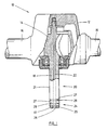
- a grinding machine 10 which includes a motor housing or casing 12 within which is suitably supported a rotary motor, the illustrated motor being a pneumatically driven motor 14 adapted to be supplied with compressed air from a suitable source (not shown).
- the motor can be hydraulic, electric or the like.
- the dimensions of the casing 12 are such that the grinding machine may be easily handled manually.
- the casing is provided with handles 16 projecting diametrically oppositely outwardly from the casing.
- the motor 14 drives an output drive shaft 18.
- a holder device 20 Suitably connected to the output drive shaft 18 by any conventional means.
- the holder device 20 is an integral extension of the shaft 18 which constitutes a rotatable elongate drive member 21.
- the shaft 18 and drive member 21 are provided with a coaxial passageway 22 extending the length thereof and through which coolant fluid may be directed to a grinding cup 30 supported thereon, the grinding cup being shown in Figs. 3-6 and described in detail below.
- An end portion 24 of the elongate drive member 21, extending from its free end 26, is adapted to fit within a corresponding sized cavity 37 in the top surface 33 of the grinding cup 30.
- the exterior wall 25 of elongate drive member 21 in the end portion 24 is adapted to driveably engage within well 38 centrally disposed in the bottom of cavity 37.
- the exterior wall 25 of drive member 21 is machined to a hexagonal cross section and well 38 as shown in Figs 4 and 6 has a corresponding sized twelve point circular cross section.
- This design permits the free end 26 of drive member 21 to be inserted easily within well 38 without the necessity of specific alignment of the drive member and grinding cup.
- the grinding cup can simply be pushed on the drive member 21 and rotated until the end 26 of drive member 21 is pushed into well 38.
- the end 26 of drive member 21 will rotate the grinding cup without slipping when in use.
- the depth of the well 38 and the height of the machined exterior wall 25 should be sufficient to drive the grinding cup without excessive wear. A distance of 4.5mm to 4.8mm has been found to be sufficient.
- Retaining means are provided on the end portion 24 of drive member 21 to detachably retain the grinding cup 30 so that grinding cup 30 will not fly off during use but can still be easily removed or changed after use.
- the retaining means includes one or more grooves 27 in the exterior wall of the end portion 24 of drive member 21. O-rings or expansion rings 29 are inserted into the grooves 27. When the end portion 24 of drive member 21 is inserted into the grinding cup 30, the O-rings or expansion rings 29 engage the side wall 39 of cavity 37 to hold the grinding cup in place.
- grooves could be formed into side wall 39 and positioned so that the O-rings or expansion rings 29 are engaged by the grooves when the end portion 24 of drive member 21 is fully inserted into cavity 37.
- the grooves in the side wall 39 of cavity 37 be slightly larger than the groove 27 whereby the O-ring 29 will remain seated on the shaft as the grinding cup is detached. If just one O-ring 29 is used there may be a tendency for the grinding cup to pivot about the point of contact between O-ring 29 and the side wall 39 of cavity 37. Accordingly in the preferred embodiment at least two O-rings 29 are utilized to eliminate the pivot action and minimize vibration.
- a dampening element may be inserted either in cavity 37 in grinding cup 30 or on the end portion 24 of the drive member 21.
- the dampening element consists of a rubber or nylon washer 41 around a portion of the exterior wall 25 of end portion 24 of drive member 21. This washer 41 abuts against the lip 42 of well 38 in the grinding cup 30.
- the dampening element can be formed of rubber or other suitable elastomeric material.
- a second dampening element may also be inserted into the bottom of well 38 so that the free end of the drive shaft compressingly engages the second dampening element.
- the vibrations generated in the grinding cup 30 during the grinding operation are substantially absorbed by the dampening elements and are thus not transmitted to the handles 16, reducing the fatigue of the operator of the machine and providing the other advantages described herein before.
- the second washer helps prevent coolant from spraying out around the holder device and the grinding cup.
- the opening 28 of passageway 22 has a larger diameter than the passageway so that coolant can be provided to the grinding cup passageways 40.
- the end 26 of drive member 21 may be provided with a convex profile to facilitate the delivery of coolant to the passageways 40.
- Figs. 1 and 2 illustrate the end portion 24 of the drive shaft machined to a hexagonal cross section however any suitable shape can be used that will drive the grinding cup. Alternatively the end portion 24 could be threaded to screw into cavity 37.
- the grinding cup 30 consists of a lower grinding section 31 and an upper body section 32.
- the grinding section 31 and body section 32 are integrally connected to form a substantially cylindrical grinding cup having top and bottom surfaces 33 and 34 respectively.
- the grinding section 31 is formed from a material capable of grinding the tungsten carbide button bits.
- the grinding section is formed from a metal and diamond matrix.
- the peripheral edge 35 in the bottom surface 34 is beveled to facilitate the removal of steel from the face of the bit around the base of the button during grinding.
- a centrally disposed convex recess 36 is formed in the bottom surface 34 having the desired profile for the button to be ground.
- the body section 32 has a centrally disposed cavity 37 formed in the top surface 33 of the grinding cup.
- This cavity 37 is shaped and sized to permit the grinding cup to be detachably connected to the drive member 21 of the holder device and rotated during the grinding operation.
- a well 38 is provided in the bottom of cavity 37 into which the end 26 of the drive member 21 is to be inserted.
- the well 38 as noted above has a cross section adapted in combination with the cross section of the end 26 of drive member 21 to rotate the grinding cup during use.
- One or more passageways 40 connect the floor 43 of well 37 with the recess 36 in the grinding section to permit a coolant, preferably water, optionally mixed with cutting oil or a water/air mist, to be provided to the surface of the button during grinding, through outlets 44.
- the coolant prevents excessive heat generation during grinding and flushes the surface of the button of material removed during grinding.
- prior devices which only use a single centrally disposed water outlet often in combination with a slot in the grinding surface, there is a tendency for a nipple to form on the button in the area of the water outlet as there is no grinding surface in contact with the button at this point.
- three outlets 44 are shown all located off the center of recess 36 to prevent nipple formation and yet provide efficient coolant dispersal.
- the outlets are strategically located to avoid a dynamic imbalance by having more mass on one side of the grinding cup from another.
- outlets are preferably located outside the areas on the grinding surface that are exposed to the most wear in order to maximize the period of time the grinding cup can be used.
- the passageways 40 are preferably parallel to the longitudinal axis of the grinding cup so that as the grinding surface wears the outlets 44 remain in the same location. If the passageways are inclined, the outlets will migrate closer to the center of the grinding surface as the grinding surface wears. Fewer or more outlets can be provided preferably located off center to prevent nipple formation.
- the retaining means comprises one or more annular grooves 27 formed in the exterior wall 25 of the end portion 24 of drive member 21 in which an O-ring or expansion ring 29 is snugly received.
- the cup 30 is adapted to be mounted on drive member 21 by inserting the end portion 24 of drive member 21 into the cavity 37.
- the length of the end portion 24 and the depth of the cavity 37 are such that when the cup 30 is fully mounted on the holding device, the O-ring 29 received within the groove 27 is engaged by the side wall 39 of the cavity 37 as described above.
- the use of the O-ring 29 to secure the cup 30 on the holder device permits easy mounting and removal of the grinding cup 30 from the holding device 20.
- the grinding cups of the present invention can be manufactured in general by the same process conventionally used to make grinding cups: by first forming a blank for the body section by machining, casting, forging, powder metallurgy etc. The blank complete with the cavity 37 in the upper surface and well 38 is then pressed into a mould containing a hot diamond/metal mixture. The bottom surface of the blank is heated and bonds to the diamond/metal matrix. Several means of heating and bonding the diamond/metal matrix to the blank are known. Alternatively the diamond/metal matrix can be formed into the grinding section and then bonded either by a shrink fit and/or with adhesives or solder to a blank. Alternatively the blank can be formed in two sections joined by friction welding, heat and press, induction welding or the like.
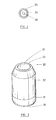
- FIGs. 7 and 8 illustrate a grinding cup 70 according to the present invention for grinding small button bits, having a top body section 72 and a smaller diameter bottom grinding section 71.
- the buttons may be closer together and accordingly in addition to reducing the diameter of the recess 76 in the grinding section 71 to match the profile of the button to be ground the diameter of the grinding section 71 also has to be reduced to fit between adjacent buttons.
- the body section 72 it is desirable to maintain a constant size for the body section 72 for two reasons: (1) the diameter of the body section must be large enough to accommodate the drive member of the holder device and (2) the cavity 77 in the top surface 73 of the grinding cup should be as large as possible so that the drive member gets a good grip on the grinding cup.
- the bottom surface 74 of the grinding section 71 has a beveled edge 75 to facilitate removal of the steel around the base of the button.
- a holder device 80 for use with a grinding machine which incorporates a diametrically extending recess at the free end of a hollow drive shaft that co-operates with a shoulder or cam means on the adjacent top surface of the grinding cup as described in either Swedish Patent No. B 460,584 or co-pending U.S. Patent Application S.N. 08/305,176.
- the holder device 80 comprises a rotatable drive member 81 having a coaxial passageway 82 along its length.
- One end 86 of the drive member is adapted to fit within the cavity 37 on the top surface of the grinding cup of the present invention.
- the wall 85 of drive member 21 is machined to a square cross section to fit within a square cavity in the grinding cup.
- other cross sections are possible that will provide the necessary rotation without slipping of the grinding cup: hexagonal, oval, circular with flattened opposite sides or threaded.
- a dampening element consisting of an elastic washer 89 is placed around the drive member in the machined end 84 and abuts against shoulder 87.
- the opening 88 of passageway 82 is expanded to permit coolant to reach the passageways 40 in the grinding cup.
- a hollow vertical upright stem 83 is centrally located on the top surface of the drive member 81.
- Cam means or shoulder 91 is provided at the base of the stem 83 and is sized to engage with the diametrically extending recess at the free end of a hollow drive shaft of the grinding machine.
- the hollow stem is inserted into the hollow drive shaft of the grinding machine and maybe held in place by one or more O-rings 60 either located in one or more grooves 61 on the stem of the grinding cup.
- the O-ring 60 when the stem 83 is inserted into the hollow drive shaft of the grinding machine engages in a groove or slot in the interior wall of the drive shaft and cam or shoulder 91 fits in the diametrically extending recess at the free end of a hollow drive shaft of the grinding machine.
- the drive member 81 is equipped with means for retaining the grinding cup.
- a peripheral groove 92 is provided in the machined wall 85 at end portion 84.
- An O-ring 90 or expansion clip or spring means is inserted into groove 92.
- the O-ring 90 engages the side wall 39 of the cavity 37.
- the stem 83 of the holder device 80 is to be inserted into a chuck on the end of the drive shaft, the O-ring 60 and shoulder 91 may be eliminated.
- a holder device for use with a grinding machine which incorporates a threaded end on the drive shaft to which a chuck is normally connected for holding the grinding cup.
- the holder device comprises a rotatable drive member 101 having a coaxial passageway 102 along its length.
- One end 106 of the drive member is adapted to fit within the cavity 37 on the top surface of the grinding cup of the present invention.
- the wall 105 of drive member 101 is machined to a square cross section to fit within a square cavity in the grinding cup.
- a dampening element consisting of an elastic washer 109 is placed around the drive member in the machined end and abuts against shoulder 107.
- the opening 108 of passageway 102 is expanded to permit coolant to reach the passageways 40 in the grinding cup.
- a threaded hole 103 is centrally located on the top surface of the drive member 101 and is coaxial with passageway 102.
- the holder device can be screwed on to the threaded end of a hollow drive shaft of the grinding machine.
- the drive member 101 is equipped with means for retaining the grinding cup as in Fig. 9.
- a peripheral groove 112 is provided in the machined wall 105.
- An O-ring 110 or expansion clip or spring means is inserted into groove 112. When the end portion 106 is inserted into the cavity 37 of the grinding cup the O-ring 110 engages with the side wall 39 of cavity 37.
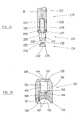
- Figs. 12 and 13 illustrate an alternative configuration for the holder device and grinding cup.
- a holder device 120 Suitably connected to the output drive shaft 18 of a grinding machine by any conventional means is a holder device 120.
- the holder device 120 is an integral extension of the shaft 18 which constitutes a rotatable elongate drive member 121.
- the shaft 18 and drive member 121 are provided with a coaxial passageway 122 extending the length thereof and through which coolant fluid may be directed to a grinding cup 130 supported thereon, the grinding cup being shown in Fig. 13 and described in detail below.
- An end portion 124 of the elongate drive member 121 extending from its free end 126, is adapted to fit within a corresponding sized centrally disposed cavity 137 in the top surface 133 of the grinding cup 130.
- the end portion 124 of elongate drive member 121 has an upper drive section 125 and a lower support section 127.
- the upper drive section 125 is adapted to driveably engage within the top portion 138 of cavity 137.
- the upper drive section 125 of drive member 121 is machined to a hexagonal cross section and the top portion 138 of cavity 137 in grinding cup 130 has a corresponding sized twelve point circular cross section.
- This design permits the upper drive section 125 of drive member 121 to be inserted easily within the top portion 138 of cavity 137 without the necessity of specific alignment of the drive member and grinding cup.
- the grinding cup can simply be pushed on the drive member 121 and rotated until the upper drive section 125 is pushed into the top portion 138 of cavity 137.
- the upper drive section 125 will rotate the grinding cup without slipping when in use. Accordingly the depth of the top portion 138 of cavity 137 and the height of the machined exterior wall of upper drive section 125 should be sufficient to drive the grinding cup without excessive wear. A distance of 4.5mm to 4.8mm has been found to be sufficient.
- the lower support section 127 of drive member 121 is adapted to fit snugly within the bottom portion 139 of cavity 137 in grinding cup 130.
- both the lower support section 127 and the bottom portion 139 of cavity 137 have a circular cross section slightly smaller in diameter than the drive section 125.
- Retaining means are provided on the lower support section 127 of drive member 121 to detachably retain the grinding cup 130 so that grinding cup 130 will not fly off during use but can still be easily removed or changed after use.
- the retaining means includes one or more grooves 140 in the exterior wall of the lower support section 127 of drive member 121.
- O-rings or expansion rings 141 are inserted into the grooves 140.
- the O-rings or expansion rings 141 engage the side wall 142 of the bottom portion 139 of cavity 137 to hold the grinding cup in place.
- grooves could be formed into side wall 142 and positioned so that the O-rings or expansion rings 141 are engaged by the grooves when the lower support section 127 of drive member 121 is fully inserted into cavity 137.
- the grooves in the side wall 142 of cavity 137 be slightly larger than the groove 140 on the lower support section 127 of drive member 121 whereby the O-ring 141 will remain seated on the support section as the grinding cup is detached. If just one O-ring 141 is used there may be a tendency for the grinding cup to pivot about the point of contact between O-ring 141 and the side wall 142 of cavity 137. Accordingly in the preferred embodiment at least two O-rings 140 are utilized to eliminate the pivot action and minimize vibration.
- a dampening element may be inserted either in cavity 137 in grinding cup 130 or on the end portion 124 of the drive member 121.
- the dampening element consists of a rubber or nylon washer 143 around the top of the upper drive section 125 of end portion 124 of drive member 121. This washer 143 abuts against the lip 144 of the top portion 138 of cavity 137 in the grinding cup 130.
- the dampening element can be formed of rubber or other suitable elastomeric material.
- a second dampening element may also be inserted into the bottom portion 139 of cavity 137 so that the free end 126 of the drive member 121 compressingly engages the second dampening element.
- the vibrations generated in the grinding cup 130 during the grinding operation are substantially absorbed by the dampening elements and are thus not transmitted to the handles 16, reducing the fatigue of the operator of the machine and providing the other advantages described herein before.
- the second washer helps prevent coolant from spraying out around the holder device and the grinding cup.
- the opening 145 of passageway 122 has a larger diameter than the passageway so that coolant can be provided to the grinding cup passageways 146.
- the free end 126 of drive member 121 may be provided with a convex profile to facilitate the delivery of coolant to the passageways 146.
- Fig. 12 illustrates the drive section 125 of end portion 124 of the drive member 121 machined to a hexagonal cross section however any suitable shape can be used that will drive the grinding cup. Alternatively the drive section 125 could be threaded to screw into cavity 137.
- the grinding cup 130 consists of a lower grinding section 131 and an upper body section 132.
- the grinding section 131 and body section 132 are integrally connected to form a substantially cylindrical grinding cup having top and bottom surfaces 133 and 134 respectively.
- the grinding section 131 is formed from a material capable of grinding the tungsten carbide button bits.
- the grinding section is formed from a metal and diamond matrix.
- the peripheral edge 135 in the bottom surface 134 is beveled to facilitate the removal of steel from the face of the bit around the base of the button during grinding.
- a centrally disposed convex recess 136 is formed in the bottom surface 134 having the desired profile for the button to be ground.
- the body section 132 has a centrally disposed cavity 137 formed in the top surface 133 of the grinding cup.
- This cavity 137 is shaped and sized to permit the grinding cup to be detachably connected to the drive member 121 of the holder device and rotated during the grinding operation.
- the cavity 137 as noted above has a cross section adapted in combination with the cross section of the end portion 124 of drive member 121 to rotate the grinding cup during use.
- One or more passageways 144 connect cavity 137 with the recess 136 in the grinding section to permit a coolant, preferably water, optionally mixed with cutting oil or a water/air mist, to be provided to the surface of the button during grinding, through outlets 146.
- the coolant prevents excessive heat generation during grinding and flushes the surface of the button of material removed during grinding.
- prior devices which only use a single centrally disposed water outlet often in combination with a slot in the grinding surface, there is a tendency for a nipple to form on the button in the area of the water outlet as there is no grinding surface in contact with the button at this point.
- two outlets 146 are shown both located off the center of recess 136 to prevent nipple formation and yet provide efficient coolant dispersal.
- the outlets are strategically located to avoid a dynamic imbalance by having more mass on one side of the grinding cup from another.
- outlets are preferably located outside the areas on the grinding surface that are exposed to the most wear in order to maximize the period of time the grinding cup can be used.
- the passageways 144 are preferably parallel to the longitudinal axis of the grinding cup to maintain the position of outlets 146 as the grinding surface on recess 136 is worn. Fewer or more outlets can be provided preferably located off center to prevent nipple formation.
- outlets 146 located at a point wider than the diameter of the bottom portion 139 of cavity 137.
- the passageways 146 are straight up and down and outlets 147 will remain on the same spot of the grinding surface as the grinding cup becomes worn.
- Fig. 14 illustrates another embodiment of the holder device according to the present invention for use with the grinding cup of Fig. 13.
- the output drive shaft 18 has a co-axial channel 222 extending from its free end 226 and connecting to passageway 122.
- a holder device 220 consists of a spindle 221 sized to fit within channel 222, an upper drive section 225 and a lower support section 227.
- a sleeve 228 is inserted into channel 222.
- the spindle 221 is then pushed into the channel 222.
- the sleeve 228 is formed of vulcanized rubber, elastomeric material or the like and helps reduce vibration and wear on the bearings of the grinding machine.
- the thickness and hardness of the sleeve 228 will determine how much vibration can be reduced. Once the spindle 221 is inserted into sleeve 228 it is not intended to be removed but to be a permanent connection. However if the drive section 225 becomes worn or it is otherwise desired to remove the holder device 220 from the output shaft, the sleeve could be removed.
- the upper drive section 225 is adapted to driveably engage within the top portion 138 of cavity 137 of grinding cup 130. As in Fig. 12 the upper drive section preferably has a hexagonal cross section.
- a co-axial passageway 229 extends through the length of holder device 220 and through which coolant fluid may be directed to the grinding cup.
- the lower support section 227 has attached at its free end 230 a detachable end part 231 which is threaded into the free end 230.
- An internal hex socket 232 permits end part 231 to be tightened into the free end 230 of the lower support section 227.
- Retaining means are provided on the lower support section 227 to detachably retain the grinding cup 130 so that grinding cup 130 will not fly off during use but can still be easily removed or changed after use.
- the retaining means includes one or more grooves 240 in the exterior wall of the lower support section 227. O-rings or expansion rings 241 are inserted into the grooves 240.
- the end part 231 When the lower support section 227 is inserted into the grinding cup 130, the O-rings or expansion rings 241 engage the side wall 142 of the bottom portion 139 of cavity 137 to hold the grinding cup in place.
- the end part Immediately below the threads 233 on end part 231 the end part is adapted by lip 234 so that when attached to the lower support section 237 a peripheral groove is formed similar to groove 240 to hold an O-ring.
- the end of the drive member In hand held machines it is the end of the drive member that is most likely to get damaged.
- the hex socket 232 in end part 231 communicates with passageway 229 to permit coolant to be provided to the grinding cup.
- end part 231 can be provided with lateral discharge ports 235 that permit coolant to be provided to recess 150 in the grinding cup.
- the recess 150 permits coolant to be delivered to the passageways 146 which for larger diameter grinding cups may need to off center wider than the diameter of cavity 127.
- the end part 231 can be formed of metal or alternatively a plastic material of sufficient hardness to withstand the rigors involved in grinding but will also act as a vibration dampening element and/or washer to prevent coolant from spraying out around the holder device.
- the holder device 20 being an integral extension of output drive shaft 18
- the holder device could consist of a separate component adapted to be connected to the end of the output drive shaft 18 by co-operating threads, chuck etc.
- two or more O-rings could be mounted on the drive member 21 to engage in cooperative recesses formed in the side wall of the cavity 37 in the grinding cup to more securely and more stably connect the grinding cup to the grinding machine.
- the retaining means could consist of one or more steel beads spring biased in a slot(s) in the wall 25 of drive member 21 and adapted to engage with a slot in the side wall 39 of cavity 37 in the grinding cup.
- a coil spring could be utilized.
- the shaft opening 22 also can permit coolant air to be passed to the grinding surface of recess 36 to extract heat therefrom.
- the holder device of the present invention can be used with the hand held grinding machine illustrated in Fig. 1 or with semi automatic grinding apparatus where the grinding head is carried on a robot arm or similar device.
- the concept of using a sleeve to reduce vibration as shown in Fig. 14 can be incorporated into the design of the holder devices shown in the other Figs.
Landscapes
- Engineering & Computer Science (AREA)
- Mechanical Engineering (AREA)
- Polishing Bodies And Polishing Tools (AREA)
- Finish Polishing, Edge Sharpening, And Grinding By Specific Grinding Devices (AREA)
Applications Claiming Priority (6)
| Application Number | Priority Date | Filing Date | Title |
|---|---|---|---|
| US383222 | 1989-07-21 | ||
| US08/383,222 US5639273A (en) | 1995-02-03 | 1995-02-03 | Grinding cup and holder device |
| AU3427495 | 1995-10-16 | ||
| AU34274/95A AU699102B2 (en) | 1995-02-03 | 1995-10-16 | Grinding cup and holder device |
| AU34274/95 | 1995-10-16 | ||
| PCT/CA1996/000078 WO1996023627A1 (en) | 1995-02-03 | 1996-02-05 | Grinding cup and holder device |
Publications (2)
| Publication Number | Publication Date |
|---|---|
| EP0807004A1 EP0807004A1 (en) | 1997-11-19 |
| EP0807004B1 true EP0807004B1 (en) | 2000-11-02 |
Family
ID=25622803
Family Applications (1)
| Application Number | Title | Priority Date | Filing Date |
|---|---|---|---|
| EP96901208A Expired - Lifetime EP0807004B1 (en) | 1995-02-03 | 1996-02-05 | Grinding cup and holder device |
Country Status (12)
| Country | Link |
|---|---|
| EP (1) | EP0807004B1 (zh) |
| JP (1) | JP4154504B2 (zh) |
| CN (1) | CN1116960C (zh) |
| BR (1) | BR9607018A (zh) |
| CA (1) | CA2212191C (zh) |
| DE (1) | DE69610820T2 (zh) |
| FI (1) | FI111056B (zh) |
| MX (1) | MX9705952A (zh) |
| NO (1) | NO310965B1 (zh) |
| NZ (1) | NZ300557A (zh) |
| RU (1) | RU2179106C2 (zh) |
| WO (1) | WO1996023627A1 (zh) |
Families Citing this family (11)
| Publication number | Priority date | Publication date | Assignee | Title |
|---|---|---|---|---|
| CA2306735C (en) * | 2000-04-27 | 2005-06-21 | Bo Thomas Sjolander | Grinding cup having optimized drive and/or contact surfaces |
| BRPI1007756B1 (pt) | 2009-05-13 | 2020-06-23 | 3M Innovative Propereties Company | Conector de liberação rápida para um acessório de ferramenta elétrica |
| EP2522459B1 (en) | 2010-01-13 | 2014-11-12 | A.L.M.T. Corp. | Super-abrasive grain wheel, wafer manufacturing method using same, and wafer |
| JP5746645B2 (ja) | 2012-02-03 | 2015-07-08 | 株式会社マキタ | 作業工具 |
| NO2884309T3 (zh) | 2013-08-01 | 2018-09-08 | ||
| DE202013006920U1 (de) | 2013-08-01 | 2014-11-03 | C. & E. Fein Gmbh | Werkzeugeinrichtung |
| DE202013006900U1 (de) | 2013-08-01 | 2014-11-03 | C. & E. Fein Gmbh | Werkzeugmaschine |
| CA2870784A1 (en) * | 2014-11-13 | 2016-05-13 | C.M.E. Blasting & Mining Equipment Ltd. | Grinding tool for buttons on a rock drill bit |
| US20160169171A1 (en) * | 2014-12-15 | 2016-06-16 | Ford Global Technologies, Llc. | Modular intake manifold |
| JP7096032B2 (ja) | 2018-03-28 | 2022-07-05 | 株式会社マキタ | マルチツール |
| CA3048076A1 (en) * | 2019-06-25 | 2020-12-25 | C.M.E. Blasting & Mining Equipment Ltd. | Grinding tool for grinding buttons on a rock drill bit |
Family Cites Families (5)
| Publication number | Priority date | Publication date | Assignee | Title |
|---|---|---|---|---|
| DE1239211B (de) * | 1964-10-14 | 1967-04-20 | Wilhelm Lot K G Optikmaschinen | Kardanisch gelagertes Optik-Schleif- oder Polierwerkzeug |
| US4385854A (en) * | 1979-08-21 | 1983-05-31 | Miyakawa Industry Co., Ltd. | Collet chuck assembly for taps |
| DE9016232U1 (zh) * | 1990-11-29 | 1991-03-21 | Fa. Andreas Stihl, 7050 Waiblingen, De | |
| US5213347A (en) * | 1991-04-29 | 1993-05-25 | Lisle Corporation | Socket driveable tap apparatus |
| SE9201835L (sv) * | 1992-06-15 | 1993-10-18 | Uniroc Grinding Ab | Vibrationsdämpande slipkopp för slipning av hårdmetallstift hos stiftborrkronor och hållare för en sådan slipkopp |
-
1996
- 1996-02-05 RU RU97114792A patent/RU2179106C2/ru active
- 1996-02-05 DE DE69610820T patent/DE69610820T2/de not_active Expired - Fee Related
- 1996-02-05 EP EP96901208A patent/EP0807004B1/en not_active Expired - Lifetime
- 1996-02-05 NZ NZ300557A patent/NZ300557A/xx unknown
- 1996-02-05 CN CN96192600A patent/CN1116960C/zh not_active Expired - Lifetime
- 1996-02-05 BR BR9607018A patent/BR9607018A/pt not_active IP Right Cessation
- 1996-02-05 JP JP52313696A patent/JP4154504B2/ja not_active Expired - Lifetime
- 1996-02-05 WO PCT/CA1996/000078 patent/WO1996023627A1/en active Search and Examination
- 1996-02-05 MX MX9705952A patent/MX9705952A/es unknown
- 1996-02-05 CA CA002212191A patent/CA2212191C/en not_active Expired - Lifetime
-
1997
- 1997-08-04 NO NO19973577A patent/NO310965B1/no not_active IP Right Cessation
- 1997-08-04 FI FI973220A patent/FI111056B/fi not_active IP Right Cessation
Also Published As
| Publication number | Publication date |
|---|---|
| NO973577L (no) | 1997-10-01 |
| CA2212191A1 (en) | 1996-08-08 |
| FI111056B (fi) | 2003-05-30 |
| MX9705952A (es) | 1998-02-28 |
| FI973220A0 (fi) | 1997-08-04 |
| NO973577D0 (no) | 1997-08-04 |
| NO310965B1 (no) | 2001-09-24 |
| CA2212191C (en) | 2001-01-30 |
| BR9607018A (pt) | 1997-10-28 |
| WO1996023627A1 (en) | 1996-08-08 |
| CN1178494A (zh) | 1998-04-08 |
| EP0807004A1 (en) | 1997-11-19 |
| DE69610820D1 (de) | 2000-12-07 |
| JPH11502468A (ja) | 1999-03-02 |
| DE69610820T2 (de) | 2001-03-01 |
| JP4154504B2 (ja) | 2008-09-24 |
| NZ300557A (en) | 1999-02-25 |
| CN1116960C (zh) | 2003-08-06 |
| FI973220A (fi) | 1997-10-02 |
| RU2179106C2 (ru) | 2002-02-10 |
Similar Documents
| Publication | Publication Date | Title |
|---|---|---|
| US5727994A (en) | Grinding cup and holder device | |
| EP0807004B1 (en) | Grinding cup and holder device | |
| US20170304983A1 (en) | Grinding tool for buttons on a rock drill bit | |
| US7811155B2 (en) | Grinding member for buttons on rock drill bit | |
| US6835114B2 (en) | Grinding tool for buttons of a rock drill bit | |
| AU2001254560A1 (en) | Grinding tool for buttons of a rock drill bit | |
| MXPA97005952A (en) | Tripuration vessel and retene device | |
| CA2363352C (en) | Grinding member for buttons on a rock drill bit | |
| AU711663B2 (en) | Grinding cup and holder device | |
| AU2001239059B2 (en) | Mass reduced grinding cup | |
| CN114025918B (zh) | 用于研磨凿岩钻头上的球齿的研磨工具 | |
| CA2404156C (en) | Grinding tool for buttons of a rock drill bit | |
| US20220362861A1 (en) | Grinding tool for grinding buttons on a rock drill bit | |
| CA2402264C (en) | Mass reduced grinding cup |
Legal Events
| Date | Code | Title | Description |
|---|---|---|---|
| PUAI | Public reference made under article 153(3) epc to a published international application that has entered the european phase |
Free format text: ORIGINAL CODE: 0009012 |
|
| 17P | Request for examination filed |
Effective date: 19970811 |
|
| AK | Designated contracting states |
Kind code of ref document: A1 Designated state(s): CH DE ES GB GR LI PT SE |
|
| 17Q | First examination report despatched |
Effective date: 19980909 |
|
| GRAG | Despatch of communication of intention to grant |
Free format text: ORIGINAL CODE: EPIDOS AGRA |
|
| GRAG | Despatch of communication of intention to grant |
Free format text: ORIGINAL CODE: EPIDOS AGRA |
|
| GRAG | Despatch of communication of intention to grant |
Free format text: ORIGINAL CODE: EPIDOS AGRA |
|
| GRAH | Despatch of communication of intention to grant a patent |
Free format text: ORIGINAL CODE: EPIDOS IGRA |
|
| GRAH | Despatch of communication of intention to grant a patent |
Free format text: ORIGINAL CODE: EPIDOS IGRA |
|
| GRAA | (expected) grant |
Free format text: ORIGINAL CODE: 0009210 |
|
| AK | Designated contracting states |
Kind code of ref document: B1 Designated state(s): CH DE ES GB GR LI PT SE |
|
| PG25 | Lapsed in a contracting state [announced via postgrant information from national office to epo] |
Ref country code: LI Free format text: LAPSE BECAUSE OF FAILURE TO SUBMIT A TRANSLATION OF THE DESCRIPTION OR TO PAY THE FEE WITHIN THE PRESCRIBED TIME-LIMIT Effective date: 20001102 Ref country code: ES Free format text: THE PATENT HAS BEEN ANNULLED BY A DECISION OF A NATIONAL AUTHORITY Effective date: 20001102 Ref country code: CH Free format text: LAPSE BECAUSE OF FAILURE TO SUBMIT A TRANSLATION OF THE DESCRIPTION OR TO PAY THE FEE WITHIN THE PRESCRIBED TIME-LIMIT Effective date: 20001102 |
|
| REG | Reference to a national code |
Ref country code: CH Ref legal event code: EP |
|
| REF | Corresponds to: |
Ref document number: 69610820 Country of ref document: DE Date of ref document: 20001207 |
|
| PG25 | Lapsed in a contracting state [announced via postgrant information from national office to epo] |
Ref country code: PT Free format text: LAPSE BECAUSE OF FAILURE TO SUBMIT A TRANSLATION OF THE DESCRIPTION OR TO PAY THE FEE WITHIN THE PRESCRIBED TIME-LIMIT Effective date: 20010202 |
|
| PG25 | Lapsed in a contracting state [announced via postgrant information from national office to epo] |
Ref country code: GR Free format text: LAPSE BECAUSE OF FAILURE TO SUBMIT A TRANSLATION OF THE DESCRIPTION OR TO PAY THE FEE WITHIN THE PRESCRIBED TIME-LIMIT Effective date: 20010203 |
|
| EN | Fr: translation not filed | ||
| PGFP | Annual fee paid to national office [announced via postgrant information from national office to epo] |
Ref country code: DE Payment date: 20010425 Year of fee payment: 6 |
|
| REG | Reference to a national code |
Ref country code: CH Ref legal event code: PL |
|
| PLBE | No opposition filed within time limit |
Free format text: ORIGINAL CODE: 0009261 |
|
| STAA | Information on the status of an ep patent application or granted ep patent |
Free format text: STATUS: NO OPPOSITION FILED WITHIN TIME LIMIT |
|
| 26N | No opposition filed | ||
| REG | Reference to a national code |
Ref country code: GB Ref legal event code: IF02 |
|
| PG25 | Lapsed in a contracting state [announced via postgrant information from national office to epo] |
Ref country code: DE Free format text: LAPSE BECAUSE OF NON-PAYMENT OF DUE FEES Effective date: 20020903 |
|
| PGFP | Annual fee paid to national office [announced via postgrant information from national office to epo] |
Ref country code: GB Payment date: 20141201 Year of fee payment: 20 |
|
| PGFP | Annual fee paid to national office [announced via postgrant information from national office to epo] |
Ref country code: SE Payment date: 20150223 Year of fee payment: 20 |
|
| REG | Reference to a national code |
Ref country code: GB Ref legal event code: PE20 Expiry date: 20160204 |
|
| REG | Reference to a national code |
Ref country code: SE Ref legal event code: EUG |
|
| PG25 | Lapsed in a contracting state [announced via postgrant information from national office to epo] |
Ref country code: GB Free format text: LAPSE BECAUSE OF EXPIRATION OF PROTECTION Effective date: 20160204 |