EP0806822A1 - Für das Auge ungefährlicher Lasersender mit einem einzigen Resonator für Pumplaser und optischen parametrischen Oszillator - Google Patents
Für das Auge ungefährlicher Lasersender mit einem einzigen Resonator für Pumplaser und optischen parametrischen Oszillator Download PDFInfo
- Publication number
- EP0806822A1 EP0806822A1 EP97107417A EP97107417A EP0806822A1 EP 0806822 A1 EP0806822 A1 EP 0806822A1 EP 97107417 A EP97107417 A EP 97107417A EP 97107417 A EP97107417 A EP 97107417A EP 0806822 A1 EP0806822 A1 EP 0806822A1
- Authority
- EP
- European Patent Office
- Prior art keywords
- laser
- light
- resonator cavity
- parametric oscillator
- optical parametric
- Prior art date
- Legal status (The legal status is an assumption and is not a legal conclusion. Google has not performed a legal analysis and makes no representation as to the accuracy of the status listed.)
- Granted
Links
- 230000003287 optical effect Effects 0.000 title claims abstract description 36
- 239000013078 crystal Substances 0.000 claims description 12
- 238000005086 pumping Methods 0.000 claims description 9
- 239000000463 material Substances 0.000 claims description 7
- 230000010287 polarization Effects 0.000 claims 1
- 229910019655 synthetic inorganic crystalline material Inorganic materials 0.000 description 18
- 230000008685 targeting Effects 0.000 description 9
- 238000000576 coating method Methods 0.000 description 6
- 238000002310 reflectometry Methods 0.000 description 6
- 239000011248 coating agent Substances 0.000 description 4
- DJHGAFSJWGLOIV-UHFFFAOYSA-K Arsenate3- Chemical compound [O-][As]([O-])([O-])=O DJHGAFSJWGLOIV-UHFFFAOYSA-K 0.000 description 3
- 238000000862 absorption spectrum Methods 0.000 description 3
- 229940000489 arsenate Drugs 0.000 description 3
- 230000003667 anti-reflective effect Effects 0.000 description 2
- 229910019901 yttrium aluminum garnet Inorganic materials 0.000 description 2
- 101100341661 Homo sapiens KRT1 gene Proteins 0.000 description 1
- 102100022905 Keratin, type II cytoskeletal 1 Human genes 0.000 description 1
- ZLMJMSJWJFRBEC-UHFFFAOYSA-N Potassium Chemical compound [K] ZLMJMSJWJFRBEC-UHFFFAOYSA-N 0.000 description 1
- 229910009372 YVO4 Inorganic materials 0.000 description 1
- JNDMLEXHDPKVFC-UHFFFAOYSA-N aluminum;oxygen(2-);yttrium(3+) Chemical compound [O-2].[O-2].[O-2].[Al+3].[Y+3] JNDMLEXHDPKVFC-UHFFFAOYSA-N 0.000 description 1
- 239000000919 ceramic Substances 0.000 description 1
- 239000011651 chromium Substances 0.000 description 1
- -1 chromium yttrium aluminum Chemical compound 0.000 description 1
- 238000010586 diagram Methods 0.000 description 1
- 230000009977 dual effect Effects 0.000 description 1
- 238000003780 insertion Methods 0.000 description 1
- 230000037431 insertion Effects 0.000 description 1
- 238000012986 modification Methods 0.000 description 1
- 230000004048 modification Effects 0.000 description 1
- 229910052700 potassium Inorganic materials 0.000 description 1
- 239000011591 potassium Substances 0.000 description 1
- ZDCPCNYMFTYBBX-UHFFFAOYSA-N potassium rubidium Chemical compound [K].[Rb] ZDCPCNYMFTYBBX-UHFFFAOYSA-N 0.000 description 1
- WYOHGPUPVHHUGO-UHFFFAOYSA-K potassium;oxygen(2-);titanium(4+);phosphate Chemical compound [O-2].[K+].[Ti+4].[O-]P([O-])([O-])=O WYOHGPUPVHHUGO-UHFFFAOYSA-K 0.000 description 1
- 229910052701 rubidium Inorganic materials 0.000 description 1
- IGLNJRXAVVLDKE-UHFFFAOYSA-N rubidium atom Chemical compound [Rb] IGLNJRXAVVLDKE-UHFFFAOYSA-N 0.000 description 1
- 238000002834 transmittance Methods 0.000 description 1
- LSGOVYNHVSXFFJ-UHFFFAOYSA-N vanadate(3-) Chemical compound [O-][V]([O-])([O-])=O LSGOVYNHVSXFFJ-UHFFFAOYSA-N 0.000 description 1
- 229910052727 yttrium Inorganic materials 0.000 description 1
- VWQVUPCCIRVNHF-UHFFFAOYSA-N yttrium atom Chemical compound [Y] VWQVUPCCIRVNHF-UHFFFAOYSA-N 0.000 description 1
Images

Classifications
-
- G—PHYSICS
- G01—MEASURING; TESTING
- G01S—RADIO DIRECTION-FINDING; RADIO NAVIGATION; DETERMINING DISTANCE OR VELOCITY BY USE OF RADIO WAVES; LOCATING OR PRESENCE-DETECTING BY USE OF THE REFLECTION OR RERADIATION OF RADIO WAVES; ANALOGOUS ARRANGEMENTS USING OTHER WAVES
- G01S17/00—Systems using the reflection or reradiation of electromagnetic waves other than radio waves, e.g. lidar systems
- G01S17/02—Systems using the reflection of electromagnetic waves other than radio waves
- G01S17/06—Systems determining position data of a target
- G01S17/08—Systems determining position data of a target for measuring distance only
- G01S17/10—Systems determining position data of a target for measuring distance only using transmission of interrupted, pulse-modulated waves
-
- H—ELECTRICITY
- H01—ELECTRIC ELEMENTS
- H01S—DEVICES USING THE PROCESS OF LIGHT AMPLIFICATION BY STIMULATED EMISSION OF RADIATION [LASER] TO AMPLIFY OR GENERATE LIGHT; DEVICES USING STIMULATED EMISSION OF ELECTROMAGNETIC RADIATION IN WAVE RANGES OTHER THAN OPTICAL
- H01S3/00—Lasers, i.e. devices using stimulated emission of electromagnetic radiation in the infrared, visible or ultraviolet wave range
- H01S3/10—Controlling the intensity, frequency, phase, polarisation or direction of the emitted radiation, e.g. switching, gating, modulating or demodulating
- H01S3/106—Controlling the intensity, frequency, phase, polarisation or direction of the emitted radiation, e.g. switching, gating, modulating or demodulating by controlling devices placed within the cavity
- H01S3/108—Controlling the intensity, frequency, phase, polarisation or direction of the emitted radiation, e.g. switching, gating, modulating or demodulating by controlling devices placed within the cavity using non-linear optical devices, e.g. exhibiting Brillouin or Raman scattering
- H01S3/1083—Controlling the intensity, frequency, phase, polarisation or direction of the emitted radiation, e.g. switching, gating, modulating or demodulating by controlling devices placed within the cavity using non-linear optical devices, e.g. exhibiting Brillouin or Raman scattering using parametric generation
-
- H—ELECTRICITY
- H01—ELECTRIC ELEMENTS
- H01S—DEVICES USING THE PROCESS OF LIGHT AMPLIFICATION BY STIMULATED EMISSION OF RADIATION [LASER] TO AMPLIFY OR GENERATE LIGHT; DEVICES USING STIMULATED EMISSION OF ELECTROMAGNETIC RADIATION IN WAVE RANGES OTHER THAN OPTICAL
- H01S3/00—Lasers, i.e. devices using stimulated emission of electromagnetic radiation in the infrared, visible or ultraviolet wave range
- H01S3/05—Construction or shape of optical resonators; Accommodation of active medium therein; Shape of active medium
- H01S3/08—Construction or shape of optical resonators or components thereof
- H01S3/081—Construction or shape of optical resonators or components thereof comprising three or more reflectors
-
- H—ELECTRICITY
- H01—ELECTRIC ELEMENTS
- H01S—DEVICES USING THE PROCESS OF LIGHT AMPLIFICATION BY STIMULATED EMISSION OF RADIATION [LASER] TO AMPLIFY OR GENERATE LIGHT; DEVICES USING STIMULATED EMISSION OF ELECTROMAGNETIC RADIATION IN WAVE RANGES OTHER THAN OPTICAL
- H01S3/00—Lasers, i.e. devices using stimulated emission of electromagnetic radiation in the infrared, visible or ultraviolet wave range
- H01S3/10—Controlling the intensity, frequency, phase, polarisation or direction of the emitted radiation, e.g. switching, gating, modulating or demodulating
- H01S3/11—Mode locking; Q-switching; Other giant-pulse techniques, e.g. cavity dumping
- H01S3/1123—Q-switching
- H01S3/113—Q-switching using intracavity saturable absorbers
Definitions
- This invention relates to laser systems which shift the wavelength of light emitted by the laser and, more particularly, to a laser system which utilizes the same optical resonator cavity for both the pump laser and the optical parametric oscillator.
- Eyesafe laser transmitters of the type discussed herein typically include two resonator cavities.
- a first resonator cavity operates in conjunction with the pump, and a second resonator cavity operates in conjunction with the optical parametric oscillator (OPO).
- OPO optical parametric oscillator
- the two-resonator configuration requires a total of three resonator mirrors for operation of the laser. The use of three resonator mirrors significantly complicates alignment of the mirrors.
- typical eyesafe lasers include a relatively short OPO cavity which results in high Fresnel numbers, thereby reducing the overall quality of the laser beam. Further, the spatial overlap of these cavities is often significantly limited by the present arrangements.
- a laser comprises a resonator cavity having a reflective surface on at least one end for partially reflecting light of a first wavelength within the resonator cavity and for partially reflecting light of a second wavelength within the resonator cavity.
- a pump is disposed within the resonator cavity for supplying light at a pumping frequency to the laser medium.
- An optical parametric oscillator disposed within the resonator cavity converts the light at the pumping frequency to light at an output frequency. Further, the optical parametric oscillator and the pump both are housed within the resonator cavity, and the resonator, the pump, and the optical parametric oscillator are optically aligned.
- the laser system 10 includes a first mirror 12 and a second mirror 14 defining the ends of an optical cavity 16.
- Mirror 12 includes an interior surface 18 which is high-reflectivity coated (approximately 100%) to reflect light having a wavelength of 1.06 microns and approximately 88% reflectivity coated to reflect light having a wavelength of 1.57 microns.
- Mirror 14 includes an interior surface 20 which is high-reflectivity coated (approximately 100%) to reflect light having a wavelength of 1.06 microns and partially reflectivity coated at 70% to reflect light having a wavelength of 1.57 microns.
- Mirrors 14 and 12 are preferably separated by approximately 14 centimeters. While shown as being 88% reflective of 1.57 microns, mirror 12 preferably is 100% reflective of 1.57 micron light. Further, all other components of the resonator cavity 16 are typically anti-reflective coated to absorb light at both 1.06 microns and 1.57 microns.
- a neodymium-doped yttrium aluminum garnet (Nd:YAG) rod 22 of dimensions 2.5 millimeters x 50 millimeters is flashlamp-pumped.
- both the rod 22 and the lamp are enclosed within a reflective ceramic pump cavity.
- the rod 22 provides gain for light at a wavelength of 1.06 microns.
- the Q-switch 24 initially absorbs light at 1.06 microns until a predetermined amount of energy has been absorbed. Q-switch 24 then becomes relatively transparent, thereby resulting in the onset of laser action and subsequently causing the release of stored energy as 1.06 micron light.
- the Brewster plate 26 causes the 1.06 micron light to be linearly polarized.
- the polarized 1.06 micron light after reaching sufficient intensity, is converted to 1.57 micron light by the optical parametric oscillator (OPO) 28.
- the OPO 28 includes as the active element a potassium titanyl phosphate (KTP) crystal having its Z-axis shown as projecting outward from the plane of FIG. 1.
- KTP potassium titanyl phosphate
- the optical parametric oscillator 28 and Nd:YAG rod 22 share a common resonator cavity 16.
- the reflective coatings applied to interior surface 20 of mirror 14 may be applied to the output side of OPO 28, thereby eliminating mirror 14.
- the Nd:YAG rod 22 is flashlamp-pumped or diode-pumped.
- the 1.06 micron light is Q-switched using a 0.5 optical density (low intensity transmittance) tetravalent-doped chromium yttrium aluminum garnet (Cr 4+ :YAG) crystal.
- the threshold for the laser in FIG. 1, using this Q-switch, is about 3.6 joules of electrical energy input to the flashlamp. In the embodiment described in FIG. 1, approximately 1.2 millijoules of output energy emitted from mirror 14, while approximately 0.4 millijoules of output energy in the form of 1.57 micron light is emitted from mirror 12.
- the surface coatings of Nd:YAG and Cr:YAG were anti-reflective coated at 1.064 microns but not at 1.57 microns.
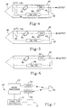
- FIGS. 4-6 depict alternative embodiments of the eyesafe laser which utilizes the single optical cavity concept.
- the resonator cavity 40 includes a single mirror 42 having deposited on an interior surface 44 a high reflectivity mirror coating to totally reflect light at a wavelength of 1.06 microns and to partially reflect light at a wavelength of 1.57 microns.
- the resonator cavity 40 also includes a corner cube or folding prism 46, which enables a single mirror design.
- the Q-switch 48 comprising a Cr 4+ :YAG crystal extending across both legs of the folded resonator cavity 40.
- the Nd:YAG rod 58 is flashlamp-pumped. The rod 58 provides gain for light at a wavelength of 1.06 microns.
- Q-switch 48 operates as described with respect to FIG. 1 to absorb light at 1.06 microns, then release the stored energy subsequent to the onset of laser action.
- the Brewster plate 50 causes the 1.06 micron light to be linearly polarized.
- OPO 52 includes a KTP crystal and converts the 1.06 micron light, after it reaches a sufficient intensity, to 1.57 micron light. The 1.57 micron light is then partially transmitted through the mirror 42 to provide an output laser beam.
- a particular advantage realized by the folded resonator 40 of FIG. 4 is that the resonator may be optically aligned prior to insertion of the Q-switch 48. That is, inserting the Q-switch does not disturb the alignment of the folded resonator configuration 40.
- FIG. 5 is arranged similarly to that of FIG. 4 and like elements will be referred to using like reference numerals.
- FIG. 5 includes the same elements as described with respect to FIG. 4 except note that in FIG. 5, the Q-switch 48 extends only across one leg of the folded resonator cavity 40.
- FIG. 6 depicts a folding resonator cavity 40 arranged similarly to that described in FIGS. 4 and 5.
- FIG. 6 further includes a combined Q-switch and Brewster plate 56 which performs the dual function of increasing the intensity of and polarizing light at 1.06 microns.
- a targeting system 60 which includes one of the laser as described in FIGS. 1 and 4-6.
- the targeting system 60 includes a range processor 62.
- Range processor 62 provides control signals to a laser 64, which may be any of the lasers as described with respect to FIGS. 1 and 4-6.
- the laser 64 outputs a single (or repeated) pulse directed to an object 66 which has been selected for targeting.
- the laser pulse reflects off of object 66 back in the direction of the laser 64.
- a sensor 68 detects the reflected pulse.
- the sensor 68 provides an input signal to range processor 62.
- Range processor 62 determines the distance between the laser 64/sensor 68 and the object 66.
- Range processor 62 determines the distance in accordance with the time differential between the sending of the pulse by laser 64 and the receiving of the pulse by sensor 68. Range processor 62 then computes the distance and outputs the distance to targeting controlling 70. Targeting controller 70 then determines a targeting solution in accordance with the distance provided by range processor 62 and other inputs (not shown). Targeting controller then outputs the targeting solution to a tracking device 72 whose orientation may be controlled by targeting controller 70 in accordance with the range information provided by range processor 62.
- the configuration of the present invention which uses the same optical resonator cavity for both the pump laser and the optical parametric oscillator, provides a much simpler configuration.
- the simpler configuration eliminates a resonator mirror, which in turn significantly simplifies optical alignment of the device.
- the simplified optical alignment also provides for a much longer optical parametric oscillator cavity, which ultimately results is better spacial overlap of the pump and OPO cavity modes, thereby providing an improved laser output.
Landscapes
- Physics & Mathematics (AREA)
- Electromagnetism (AREA)
- Engineering & Computer Science (AREA)
- Computer Networks & Wireless Communication (AREA)
- General Physics & Mathematics (AREA)
- Radar, Positioning & Navigation (AREA)
- Remote Sensing (AREA)
- Nonlinear Science (AREA)
- Plasma & Fusion (AREA)
- Optics & Photonics (AREA)
- Lasers (AREA)
- Optical Modulation, Optical Deflection, Nonlinear Optics, Optical Demodulation, Optical Logic Elements (AREA)
Applications Claiming Priority (2)
| Application Number | Priority Date | Filing Date | Title |
|---|---|---|---|
| US646200 | 1984-08-31 | ||
| US08/646,200 US5687186A (en) | 1996-05-07 | 1996-05-07 | Eyesafe laser transmitter with single resonator cavity for both pump laser and optical parametric oscillator |
Publications (2)
| Publication Number | Publication Date |
|---|---|
| EP0806822A1 true EP0806822A1 (de) | 1997-11-12 |
| EP0806822B1 EP0806822B1 (de) | 2002-10-09 |
Family
ID=24592167
Family Applications (1)
| Application Number | Title | Priority Date | Filing Date |
|---|---|---|---|
| EP97107417A Expired - Lifetime EP0806822B1 (de) | 1996-05-07 | 1997-05-06 | Laser mit einem einzigen Resonator für Pumplaser-Medium und optischen parametrischen Oszillator |
Country Status (8)
| Country | Link |
|---|---|
| US (1) | US5687186A (de) |
| EP (1) | EP0806822B1 (de) |
| JP (1) | JP3217988B2 (de) |
| CA (1) | CA2204563C (de) |
| DE (1) | DE69716160T2 (de) |
| ES (1) | ES2184003T3 (de) |
| IL (1) | IL120773A (de) |
| NO (1) | NO972064L (de) |
Cited By (2)
| Publication number | Priority date | Publication date | Assignee | Title |
|---|---|---|---|---|
| EP1054487A3 (de) * | 1999-05-14 | 2002-10-02 | Raytheon Company | Leichte integrierte optische Bank und miniaturisierter Lasersender unter Verwendung derselben |
| EP1589335A3 (de) * | 2004-04-20 | 2006-01-25 | Lockheed Martin Corporation | System und vorrichtung für auge ungefährliches ultraschalldetektion |
Families Citing this family (11)
| Publication number | Priority date | Publication date | Assignee | Title |
|---|---|---|---|---|
| US5841798A (en) * | 1996-05-07 | 1998-11-24 | Raytheon Company | Eyesafe laser transmitter with brewster angle Q switch in single resonator cavity for both pump laser and optical parametric oscillator |
| US5790303A (en) * | 1997-01-23 | 1998-08-04 | Positive Light, Inc. | System for amplifying an optical pulse using a diode-pumped, Q-switched, intracavity-doubled laser to pump an optical amplifier |
| US6122097A (en) * | 1998-04-16 | 2000-09-19 | Positive Light, Inc. | System and method for amplifying an optical pulse using a diode-pumped, Q-switched, extracavity frequency-doubled laser to pump an optical amplifier |
| US6650682B1 (en) | 1999-04-30 | 2003-11-18 | University Of New Mexico | Bi-directional short pulse ring laser |
| RU2176839C1 (ru) * | 2001-01-12 | 2001-12-10 | Федеральное государственное унитарное предприятие "Научно-исследовательский институт "Полюс" им. М.Ф. Стельмаха | Способ внутрирезонаторной параметрической генерации света |
| US7068689B2 (en) * | 2001-01-18 | 2006-06-27 | Spectra-Physics Gmbh | Frequency-converted laser apparatus with frequency conversion crystals |
| JP4069894B2 (ja) * | 2004-03-30 | 2008-04-02 | 三菱電機株式会社 | 固体レーザ装置 |
| US7039087B2 (en) * | 2004-05-13 | 2006-05-02 | The United States Of America As Represented By The Department Of The Army | End pumped slab laser cavity |
| US10852432B2 (en) * | 2016-11-15 | 2020-12-01 | Bae Systems Information And Electronic Systems Integration Inc. | Dual mode laser target designator/rangefinder with an optical parametric oscillator-optical parametric amplifier (OPO-OPA) converter |
| US10729496B2 (en) | 2017-11-21 | 2020-08-04 | Cutera, Inc. | Dermatological picosecond laser treatment systems and methods using optical parametric oscillator |
| US11400308B2 (en) | 2017-11-21 | 2022-08-02 | Cutera, Inc. | Dermatological picosecond laser treatment systems and methods using optical parametric oscillator |
Family Cites Families (2)
| Publication number | Priority date | Publication date | Assignee | Title |
|---|---|---|---|---|
| US5457707A (en) * | 1993-08-24 | 1995-10-10 | Spectra-Physics Lasers, Inc. | Master optical parametric oscillator/power optical parametric oscillator |
| US5390211A (en) * | 1993-08-24 | 1995-02-14 | Spectra-Physics Lasers, Inc. | Optical parametric oscillator with unstable resonator |
-
1996
- 1996-05-07 US US08/646,200 patent/US5687186A/en not_active Expired - Lifetime
-
1997
- 1997-05-04 IL IL12077397A patent/IL120773A/xx not_active IP Right Cessation
- 1997-05-05 NO NO972064A patent/NO972064L/no not_active Application Discontinuation
- 1997-05-06 DE DE69716160T patent/DE69716160T2/de not_active Expired - Fee Related
- 1997-05-06 EP EP97107417A patent/EP0806822B1/de not_active Expired - Lifetime
- 1997-05-06 ES ES97107417T patent/ES2184003T3/es not_active Expired - Lifetime
- 1997-05-06 CA CA002204563A patent/CA2204563C/en not_active Expired - Fee Related
- 1997-05-07 JP JP11698397A patent/JP3217988B2/ja not_active Expired - Fee Related
Non-Patent Citations (3)
| Title |
|---|
| AMMANN E O ET AL: "Efficient internal optical parametric oscillation", APPLIED PHYSICS LETTERS, 15 APRIL 1970, USA, vol. 16, no. 8, ISSN 0003-6951, pages 309 - 312, XP002038175 * |
| KETTERIDGE P ET AL: "Miniature eyesafe range finder", CLEO 95. SUMMARIES OF PAPERS PRESENTED AT THE CONFERENCE ON LASERS AND ELECTRO-OPTICS (IEEE CAT. NO. 95CH35800), CLEO 95. CONFERENCE ON LASERS AND ELECTRO-OPTICS. (PAPERS IN SUMMARY FORM ONLY RECEIVED), BALTIMORE, MA, USA, 22-26 MAY 1995, ISBN 0-7803-2659-8, 1995, WASHINGTON, DC, USA, OPT. SOC. AMERICA, USA, pages 257, XP002038173 * |
| L.R.MARSHALL ET AL.: "Nonlinear cavity dumping", CONFERENCE ON LASER AND ELECTRO-OPTICS,VOL. 11 1993 OSA TECHNICAL DIGEST SERIES,PAPER CTHK7, XP002038174 * |
Cited By (3)
| Publication number | Priority date | Publication date | Assignee | Title |
|---|---|---|---|---|
| EP1054487A3 (de) * | 1999-05-14 | 2002-10-02 | Raytheon Company | Leichte integrierte optische Bank und miniaturisierter Lasersender unter Verwendung derselben |
| EP1589335A3 (de) * | 2004-04-20 | 2006-01-25 | Lockheed Martin Corporation | System und vorrichtung für auge ungefährliches ultraschalldetektion |
| US7791739B2 (en) | 2004-04-20 | 2010-09-07 | Lockheed Martin Corporation | System and method to enable eye-safe laser ultrasound detection |
Also Published As
| Publication number | Publication date |
|---|---|
| DE69716160D1 (de) | 2002-11-14 |
| EP0806822B1 (de) | 2002-10-09 |
| DE69716160T2 (de) | 2003-06-05 |
| IL120773A0 (en) | 1997-09-30 |
| JPH1065253A (ja) | 1998-03-06 |
| NO972064D0 (no) | 1997-05-05 |
| US5687186A (en) | 1997-11-11 |
| CA2204563C (en) | 2001-07-17 |
| IL120773A (en) | 2000-06-01 |
| JP3217988B2 (ja) | 2001-10-15 |
| CA2204563A1 (en) | 1997-11-07 |
| NO972064L (no) | 1997-11-10 |
| ES2184003T3 (es) | 2003-04-01 |
Similar Documents
| Publication | Publication Date | Title |
|---|---|---|
| US4797893A (en) | Microlaser system | |
| US5218610A (en) | Tunable solid state laser | |
| EP0715774B1 (de) | Tiefblauer mikrolaser | |
| US6108356A (en) | Intracavity optical parametric oscillators | |
| EP0943167B1 (de) | Frequenzumwandlungslaser | |
| US5687186A (en) | Eyesafe laser transmitter with single resonator cavity for both pump laser and optical parametric oscillator | |
| US5991012A (en) | Eyesafe laser transmitter with brewster angle Q-switch in single resonator cavity for both pump laser and optical parametric oscillator | |
| US4292602A (en) | Laser resonator | |
| KR100269028B1 (ko) | 반일체 고리형 공진기를 이용한 단방향 발진 레이저 장치 | |
| US5121402A (en) | Multiple element ring laser | |
| KR0169538B1 (ko) | 모노리식 다기능 광 소자 및 이를 사용하여 구성된 장치 | |
| US4796262A (en) | Optical resonator using a passive Q switch or other optical element with low-damage threshold | |
| US5636232A (en) | Optical wavelength converter | |
| US5230004A (en) | Narrow beam oscillator and large volume amplifier utilizing same gain medium | |
| US6650685B2 (en) | Single laser transmitter for Q-switched and mode-locked vibration operation | |
| IL143959A (en) | Eyesafe laser transmitter with brewster angle q-switch in single resonator cavity for both pump laser and optical parametric oscillator | |
| EP1281219B1 (de) | Einzellasersender für q-umschalt- und modenverriegelten vibrationsbetrieb | |
| US5394428A (en) | Controlled, high-power laser oscillator | |
| US6320894B1 (en) | High energy Q-switched 0.9 μm laser | |
| JPH0697545A (ja) | 固体レーザ装置 | |
| GB2040549A (en) | Improvements Relating to Laser Apparatus | |
| JPH05211369A (ja) | レーザーダイオードポンピング固体レーザー | |
| JPH0990450A (ja) | 光発振器 |
Legal Events
| Date | Code | Title | Description |
|---|---|---|---|
| PUAI | Public reference made under article 153(3) epc to a published international application that has entered the european phase |
Free format text: ORIGINAL CODE: 0009012 |
|
| AK | Designated contracting states |
Kind code of ref document: A1 Designated state(s): CH DE ES FR GB IT LI |
|
| 17P | Request for examination filed |
Effective date: 19980418 |
|
| RAP1 | Party data changed (applicant data changed or rights of an application transferred) |
Owner name: RAYTHEON COMPANY |
|
| RTI1 | Title (correction) |
Free format text: LASER WITH SINGLE RESONATOR CAVITY FOR BOTH PUMP LASER MEDIUM AND OPTICAL PARAMETRIC OSCILLATOR |
|
| GRAG | Despatch of communication of intention to grant |
Free format text: ORIGINAL CODE: EPIDOS AGRA |
|
| GRAG | Despatch of communication of intention to grant |
Free format text: ORIGINAL CODE: EPIDOS AGRA |
|
| GRAH | Despatch of communication of intention to grant a patent |
Free format text: ORIGINAL CODE: EPIDOS IGRA |
|
| 17Q | First examination report despatched |
Effective date: 20020318 |
|
| GRAH | Despatch of communication of intention to grant a patent |
Free format text: ORIGINAL CODE: EPIDOS IGRA |
|
| GRAA | (expected) grant |
Free format text: ORIGINAL CODE: 0009210 |
|
| AK | Designated contracting states |
Kind code of ref document: B1 Designated state(s): CH DE ES FR GB IT LI |
|
| REG | Reference to a national code |
Ref country code: GB Ref legal event code: FG4D |
|
| REG | Reference to a national code |
Ref country code: CH Ref legal event code: EP |
|
| REF | Corresponds to: |
Ref document number: 69716160 Country of ref document: DE Date of ref document: 20021114 |
|
| REG | Reference to a national code |
Ref country code: CH Ref legal event code: NV Representative=s name: ISLER & PEDRAZZINI AG |
|
| ET | Fr: translation filed | ||
| REG | Reference to a national code |
Ref country code: ES Ref legal event code: FG2A Ref document number: 2184003 Country of ref document: ES Kind code of ref document: T3 |
|
| PLBE | No opposition filed within time limit |
Free format text: ORIGINAL CODE: 0009261 |
|
| STAA | Information on the status of an ep patent application or granted ep patent |
Free format text: STATUS: NO OPPOSITION FILED WITHIN TIME LIMIT |
|
| 26N | No opposition filed |
Effective date: 20030710 |
|
| PGFP | Annual fee paid to national office [announced via postgrant information from national office to epo] |
Ref country code: FR Payment date: 20040408 Year of fee payment: 8 |
|
| PGFP | Annual fee paid to national office [announced via postgrant information from national office to epo] |
Ref country code: CH Payment date: 20040413 Year of fee payment: 8 |
|
| PGFP | Annual fee paid to national office [announced via postgrant information from national office to epo] |
Ref country code: GB Payment date: 20040415 Year of fee payment: 8 |
|
| PGFP | Annual fee paid to national office [announced via postgrant information from national office to epo] |
Ref country code: DE Payment date: 20040422 Year of fee payment: 8 |
|
| PGFP | Annual fee paid to national office [announced via postgrant information from national office to epo] |
Ref country code: ES Payment date: 20040510 Year of fee payment: 8 |
|
| PG25 | Lapsed in a contracting state [announced via postgrant information from national office to epo] |
Ref country code: IT Free format text: LAPSE BECAUSE OF NON-PAYMENT OF DUE FEES;WARNING: LAPSES OF ITALIAN PATENTS WITH EFFECTIVE DATE BEFORE 2007 MAY HAVE OCCURRED AT ANY TIME BEFORE 2007. THE CORRECT EFFECTIVE DATE MAY BE DIFFERENT FROM THE ONE RECORDED. Effective date: 20050506 Ref country code: GB Free format text: LAPSE BECAUSE OF NON-PAYMENT OF DUE FEES Effective date: 20050506 |
|
| PG25 | Lapsed in a contracting state [announced via postgrant information from national office to epo] |
Ref country code: ES Free format text: LAPSE BECAUSE OF NON-PAYMENT OF DUE FEES Effective date: 20050507 |
|
| PG25 | Lapsed in a contracting state [announced via postgrant information from national office to epo] |
Ref country code: LI Free format text: LAPSE BECAUSE OF NON-PAYMENT OF DUE FEES Effective date: 20050531 Ref country code: CH Free format text: LAPSE BECAUSE OF NON-PAYMENT OF DUE FEES Effective date: 20050531 |
|
| PG25 | Lapsed in a contracting state [announced via postgrant information from national office to epo] |
Ref country code: DE Free format text: LAPSE BECAUSE OF NON-PAYMENT OF DUE FEES Effective date: 20051201 |
|
| REG | Reference to a national code |
Ref country code: CH Ref legal event code: PL |
|
| GBPC | Gb: european patent ceased through non-payment of renewal fee |
Effective date: 20050506 |
|
| PG25 | Lapsed in a contracting state [announced via postgrant information from national office to epo] |
Ref country code: FR Free format text: LAPSE BECAUSE OF NON-PAYMENT OF DUE FEES Effective date: 20060131 |
|
| REG | Reference to a national code |
Ref country code: FR Ref legal event code: ST Effective date: 20060131 |
|
| REG | Reference to a national code |
Ref country code: ES Ref legal event code: FD2A Effective date: 20050507 |