EP0806614B1 - Platte zum Befestigen von Bodenheizungsröhren - Google Patents
Platte zum Befestigen von Bodenheizungsröhren Download PDFInfo
- Publication number
- EP0806614B1 EP0806614B1 EP97201363A EP97201363A EP0806614B1 EP 0806614 B1 EP0806614 B1 EP 0806614B1 EP 97201363 A EP97201363 A EP 97201363A EP 97201363 A EP97201363 A EP 97201363A EP 0806614 B1 EP0806614 B1 EP 0806614B1
- Authority
- EP
- European Patent Office
- Prior art keywords
- plate
- plate according
- ribs
- studs
- chambers
- Prior art date
- Legal status (The legal status is an assumption and is not a legal conclusion. Google has not performed a legal analysis and makes no representation as to the accuracy of the status listed.)
- Expired - Lifetime
Links
- 238000010438 heat treatment Methods 0.000 title claims abstract description 12
- 230000002787 reinforcement Effects 0.000 claims description 8
- 239000004793 Polystyrene Substances 0.000 claims description 2
- 229920002223 polystyrene Polymers 0.000 claims description 2
- 239000011810 insulating material Substances 0.000 claims 2
- 239000000463 material Substances 0.000 claims 1
- 239000011490 mineral wool Substances 0.000 claims 1
- 239000004576 sand Substances 0.000 claims 1
- 238000009413 insulation Methods 0.000 description 21
- 230000002349 favourable effect Effects 0.000 description 1
- 238000004519 manufacturing process Methods 0.000 description 1
Images


Classifications
-
- F—MECHANICAL ENGINEERING; LIGHTING; HEATING; WEAPONS; BLASTING
- F24—HEATING; RANGES; VENTILATING
- F24D—DOMESTIC- OR SPACE-HEATING SYSTEMS, e.g. CENTRAL HEATING SYSTEMS; DOMESTIC HOT-WATER SUPPLY SYSTEMS; ELEMENTS OR COMPONENTS THEREFOR
- F24D3/00—Hot-water central heating systems
- F24D3/12—Tube and panel arrangements for ceiling, wall, or underfloor heating
- F24D3/14—Tube and panel arrangements for ceiling, wall, or underfloor heating incorporated in a ceiling, wall or floor
- F24D3/141—Tube mountings specially adapted therefor
- F24D3/142—Tube mountings specially adapted therefor integrated in prefab construction elements
-
- Y—GENERAL TAGGING OF NEW TECHNOLOGICAL DEVELOPMENTS; GENERAL TAGGING OF CROSS-SECTIONAL TECHNOLOGIES SPANNING OVER SEVERAL SECTIONS OF THE IPC; TECHNICAL SUBJECTS COVERED BY FORMER USPC CROSS-REFERENCE ART COLLECTIONS [XRACs] AND DIGESTS
- Y02—TECHNOLOGIES OR APPLICATIONS FOR MITIGATION OR ADAPTATION AGAINST CLIMATE CHANGE
- Y02B—CLIMATE CHANGE MITIGATION TECHNOLOGIES RELATED TO BUILDINGS, e.g. HOUSING, HOUSE APPLIANCES OR RELATED END-USER APPLICATIONS
- Y02B30/00—Energy efficient heating, ventilation or air conditioning [HVAC]
Definitions
- the invention relates to a plate suitable for fixing a floor heating hose, which plate is at an upper side provided with a plurality of studs to clampingly receive a floor heating hose between adjacent studs.
- the upper side of the plate is provided with a plurality of studs.
- Said studs are hollow whereby the hollow spaces in the studs form chambers at the bottom side of said plate.
- the chambers are separated from each other by horizontal extending parts of said plate.
- On the upper side tubes are located on said horizontal extending parts. This means that between the tubes and the floor only said horizontal extending part is present to provide thermal and acoustic insulation. By such plate the insulation is relatively poor.
- a plate of this kind is used for attaching floor heating hoses on a floor.
- the two-plate assembly thus formed serves to position floor heating hoses, to thermally insulate the floor and to provide contact noise insulation.
- a drawback of such an assembly is the fact that it comprises two separate plates.
- the object of the invention is to provide a plate which is suitable both for fixing a floor heating hose and for providing adequate thermal and acoustic insulation.
- said plate comprises at its underside upstanding ribs facing away from the plate and forming a regular pattern of adjacent chambers.
- the plate is supported on the floor by the ribs.
- the chambers which are bounded by the plate, the ribs provided thereon and the floor, provide a relatively satisfactory thermal insulation and contact noise insulation.
- the studs and the chambers are preferably arranged in a regular pattern with respect to each other, so that the plate is uniformly loaded when the floor is being used.
- One embodiment of the plate according to the invention is characterized in that a rib bounding said chambers is provided with a passage interconnecting the chambers arranged adjacently to each other, whereby the width of the passage is less than 30%, preferably less than 20%, of the length of a rib.
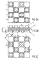
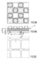
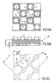
- Figures 1A, 1B and 1C show a plan view, a cross-sectional view and a bottom view respectively of a part of a first embodiment of a plate 1 according to the invention.
- Plate 1 is made of EPS, with the plate having a uniform density all over and a specific weight of 7 - 35 kg/m 3 .
- Plate 1 is provided with a plurality of studs 3 at an upper side 2, which are distributed in a regular pattern over said upper side. Said studs 3 are arranged in rows 4, 5, which are staggered with respect to each other, with the distance N1 between the studs 3 in a row 4, 5 being equal to the distance N2 between the two identical rows 4, 5.
- the distance between two different rows 4, 5 equals 1 ⁇ 2 N2 and corresponds with the distance 1 ⁇ 2 N1 over which said rows are staggered with respect to each other.
- a regular square grid of studs 3 has been obtained on upper side 2 of the plate.
- the shape of studs 3 is configured to be such such that a floor heating hose (not shown) can be clamped down between two opposite studs 3.
- the shape of studs 3 is known per se and will not be discussed in more detail, therefore.
- At a bottom side 6 remote from upper side 2 said plate is provided with a plurality of ribs 7, which extend parallel to rows 4, 5, and with a plurality of ribs 8, which extend transversely to rows 4, 5.
- Ribs 7 are spaced apart by a distance which equals 1 ⁇ 2 N2, whilst ribs 8 are spaced apart by a distance which equals 1 ⁇ 2 N1. Ribs 7 are located opposite rows 4, 5, whilst ribs 8 are arranged in such a manner that ribs 8 are alternately located opposite studs 3 of rows 4 and opposite studs 3 of rows 5.
- Studs 3 and ribs 7, 8 are integrally connected to a baseplate 9 of plate 1.
- Baseplate 9 and ribs 7, 8 bound chambers 10, which are open towards bottom side 6.
- chambers 10 are staggered with respect to studs 3 over a distance 1 ⁇ 4 N1 and 1 ⁇ 4 N2.
- a crossing 11 of two ribs 7, 8 extending transversely to each other is located under each stud 3.
- said ribs 7, 8 are supported on the floor. As a result of this it is possible to walk on plate 1 while fixing the hoses.
- the plate 12 that is shown in Figures 2A-2C is different from the plate 1 shown in Figures 1A-1C in that the ends 13 of ribs 7, 8 facing bottom side 6 are rounded. Depending on the floor on which plate 12 is used, this will provide an improved contact noise insulation.
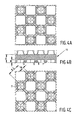
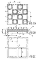
- Figures 3A-3C show a third embodiment of a plate 14 according to the invention, wherein studs 3 are located at the upper side 2 in manner similar to plate 1 of Figures 1A-1C.
- Bottom side 6 is provided with ribs 7, 8 extending transversely to each other, with ribs 7, 8 including an angle of 45° with rows 4, 5.
- the distance N3 between two parallel ribs 7 or 8 is thereby such that crossings 11 of intersecting ribs 7, 8 are located under studs 3.
- a crossing of two ribs 7, 8 is provided under each stud, while using a minimal number of ribs 7, 8.
- FIG. 4A-4C The embodiment of a plate 15 according to the invention that is shown in Figures 4A-4C is different from the plate 14 shown in Figures 3A-3C in that the ends 13 of ribs 7, 8 are rounded.
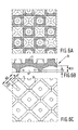
- FIGS 5A-5C show a fifth embodiment of the plate 16 according to the invention, with ribs 7, 8 including an angle of 45° with rows 4, 5.
- Ribs 7, 8 are positioned in such a manner with respect to studs 3, that crossings 11 are located between studs 3, and studs 3 are located centrally above the chambers 17 bounded by ribs 7, 8 and baseplate 9.
- Each chamber 17 is provided, at its side facing baseplate 9, with sloping walls 18 extending in the direction of stud 3, which terminate in a flat wall 19. Loads applied to plate 16 are deflected via stud 3, along walls 18, to ribs 7, 8 by baseplate 9.
- plate 16 is more resilient than for example plate 14 shown in Figures 3A-3C. Depending on the floor on which plate 16 is provided and the desired characteristics of the floor to be obtained eventually, an improved sound insulation is thus obtained.
- the plate 20 that is shown in Figures 6A-6C is different from plate 16 in that ribs 7, 8 are rounded near their ends 13.
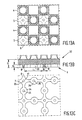
- Figures 7A-7C show a seventh embodiment of a plate 21 according to the invention, wherein ribs 7 extend parallel to rows 4, 5 and ribs 8 extend transversely to ribs 7.
- the distance between two parallel ribs 7 or 8 is equal to the distance N1 between two studs 3 in one and the same row and to the distance N2 between studs 3 from two parallel rows 4, 5.
- Ribs 7, 8 are positioned in such a manner with respect to studs 3 that crossings 11 are located centrally between four studs 3 arranged adjacently to each other. As a result of this one rib 7 or 8 extends under each stud 3.
- FIG. 8A-8C The embodiment of a plate 23 according to the invention that is shown in Figures 8A-8C is different from the plate 21 shown in Figures 7A-7C in that the ends 24 of ribs 7, 8 are rounded.
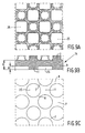
- Figures 9A-9C show an embodiment of a plate 24 according to the invention wherein chambers 25 are circular, seen in bottom view. Said circular chambers 25 are bounded by ribs 7, 8. Circular chambers 25 are positioned in such a manner that chambers 25 are located between studs 3, and that a crossing 11 of ribs 7, 8 is provided under each stud 3. As a result of the presence of circular chambers 25, stud 3 is supported over a relatively large surface area by crossing 11, which makes plate 24 relatively stiff. As a result of the presence of the relatively large chambers 25, a relatively good thermal insulation and contact noise insulation is obtained.
- FIGS 10A-10C show a plate 26 according to the invention, which is different from plate 24 in that each chamber 25 is provided with a cone 27, which is directed towards upper side 2. This will provide a further improved contact noise insulation.
- Figures 11A-11C show an eleventh embodiment of a plate 28 according to the invention, wherein ribs 7, 8 are arranged diagonally with respect to rows 4, 5.
- the distance N4 between two parallel ribs 7 is thereby twice as large as the distance N5 between two parallel ribs 8.
- Ribs 7, 8 are arranged in such a manner with respect to studs 3, that crossings 11 are located opposite studs 3.
- Half the number of studs 3 are thereby located opposite a crossing 11, whilst the other half of the number of studs is located opposite a rib 8.
- the chamber 29 bounded by ribs 7, 8 and baseplate 9 is larger than the chamber in plate 14, so that a better insulation will be obtained.
- ribs 7 extend parallel to rows 4, 5, whilst ribs 8 extend transversely to ribs 7.
- the distance between ribs 7, 8 is thereby equal to the distance N1, N2 between studs 3.
- the position of ribs 7, 8 with respect to studs 3 is such that a crossing 11 of intersecting ribs 7, 8 is located between two studs 3 of different rows 4, 5.
- Each stud 3 is supported at its bottom side by a rib 7 along one edge, by a rib 8 along another edge and by crossing 11 at a corner point.
- Chambers 31 are relatively large, as a result of which a relatively good insulation is obtained.
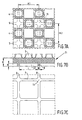
- Figures 13A-13C shown an embodiment of plate 32 according to the invention, wherein ribs 7 are located under rows 5, whilst ribs 8, which extend transversely to ribs 7, are located under studs 3 of rows 4.
- the chambers 33 formed by ribs 7, 8 are rounded near crossings 11, as a result of which crossings 11 are relatively large.
- Crossings 11 are located between four studs 3 arranged adjacently to each other.
- Rib 7, 8 is provided with a local reinforcement 34 opposite each stud 3. Both crossing 11 and local reinforcement 34 are provided with recesses 35, which are open towards bottom side 6.
- Ribs 7, 8 and crossings 11 and reinforcement 34 exhibit the same wall thickness practically all over, which is advantageous with regard to manufacturing plate 32, and which results in an advantageous behaviour when loads are applied to the plate. Ribs 7, 8 will deform when the plate is loaded, whereby said ribs will become convex. As a result of the presence of recesses 35 a similar deformation may occur near crossings 11 and reinforcements 34.
- Figures 14A-14C show an embodiment of a plate 36 according to the invention, which forms a combination of plate 28 according to Figures 11A-11C and plate 32 according to Figures 13A-13C.
- Crossings 11 and local reinforcements 34 are thereby arranged in such a manner that a crossing 11 or a support 34 is located opposite each stud 3, and vice versa.
- Figures 15A-15C show an embodiment of a plate 37 according to the invention, which is different from the plate 32 shown in Figures 13A-13C in that ribs 7, 8 are not provided with local reinforcements and in that the ends 13 of ribs 7, 8 are rounded.
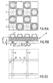
- FIGS 16A-16C show an embodiment of a plate 38 according to the invention, which is different from the plate 21 shown in Figures 7A-7C in that ribs 7, 8 are provided with passages 40 interconnecting chambers 39 arranged adjacently to each other.
- Each passage has a width B which is less than 30% and preferably less than 20% of the length of a rib 7, 8.
- the length of a rib 7, 8 of plate 38 is equal to the distance L1 between two opposite ribs plus the thickness L2 of a rib. It has become apparent that the use of such a passage having a relatively small width in comparison with the length of a rib results in an even better thermal and acoustic insulation than is the case with the thermal and acoustic insulation of plate 21 according to Figures 7A-7C.
- Ribs 7, 8 of the plates may be elastified. This means that the polystyrene ribs are temporarily subjected to a pressure load such that afterwards ribs 7, 8 will exhibit greater resilience than before.
Landscapes
- Engineering & Computer Science (AREA)
- Physics & Mathematics (AREA)
- Thermal Sciences (AREA)
- Chemical & Material Sciences (AREA)
- Combustion & Propulsion (AREA)
- Mechanical Engineering (AREA)
- General Engineering & Computer Science (AREA)
- Steam Or Hot-Water Central Heating Systems (AREA)
- Building Environments (AREA)
Claims (20)
- Platte (1), geeignet für die Befestigung eines Fußbodenheizungsschlauchs, die an ihrer Oberseite (2) mit einer Vielzahl von Stollen (3) versehen ist, wobei ein Fußbodenheizungsschlauch jeweils zwischen benachbarten Stollen eingeklemmt werden kann, dadurch gekennzeichnet, daß die genannte Platte an ihrer Unterseite mit herausragenden Rippen (7, 8) versehen ist, die von der Platte weg weisen und ein regelmäßiges Muster von benachbarten Kammern bilden.
- Platte nach Anspruch 1, dadurch gekennzeichnet, daß eine Rippe (7, 8), welche die genannten Kammern (10) begrenzt, mit einem Durchlaß versehen ist, welcher die nebeneinander angeordneten Kammern (10) miteinander verbindet, wobei die Breite des Durchlasses weniger als 30 %, vorzugsweise weniger als 20 % der Länge einer Rippe ausmacht.
- Platte nach Anspruch 1 oder 2, dadurch gekennzeichnet, daß die genannten Stollen (3) in einem regelmäßigen Gitter auf der genannten Oberseite angeordnet sind.
- Platte nach einem der vorstehenden Ansprüche, dadurch gekennzeichnet, daß die genannten Stollen (3) in einem quadratischen Gitter angeordnet sind und die genannten Kammern ebenfalls in einem ähnlich quadratisch geformten Muster angeordnet sind.
- Platte nach Anspruch 4, dadurch gekennzeichnet, daß das genannte quadratische Muster um 45° gegenüber dem genannten quadratischen Gitter gedreht ist.
- Platte nach Anspruch 4 oder 5, dadurch gekennzeichnet, daß das genannte quadratische Muster doppelt so groß ist wie das genannte quadratische Gitter.
- Platte nach Ansprüchen 1, 2 oder 3, dadurch gekennzeichnet, daß die genannten Stollen (3) in einem quadratischen Gitter angeordnet sind, während die Kammern (10) in einem rechteckigen Muster angeordnet sind, welches im Verhältnis zu dem genannten quadratischen Gitter um 45° gedreht ist.
- Platte nach einem der vorstehenden Ansprüche, dadurch gekennzeichnet, daß ein Stollen (3) mittig gegenüber einer Kammer (10) angeordnet ist.
- Platte nach einem der vorstehenden Ansprüche, dadurch gekennzeichnet, daß ein Stollen (3) gegenüber einer Kreuzung von sich schneidenden Rippen angeordnet ist.
- Platte nach einem der vorstehenden Ansprüche, dadurch gekennzeichnet, daß ein Stollen (3) gegenüber einer Rippe mittig zwischen zwei Kreuzungen von sich schneidenden Rippen (7, 8) angeordnet ist.
- Platte nach einem der vorstehenden Ansprüche, dadurch gekennzeichnet, daß ein Stollen (3) gegenüber einer Rippe angeordnet ist, wodurch die genannte Rippe (7, 8) lokal verstärkt wird.
- Platte nach einem der vorstehenden Ansprüche, dadurch gekennzeichnet, daß eine Kreuzung oder Verstärkung mit einem Vertiefung versehen ist, welche sich zur genannten Unterseite hin öffnet.
- Platte nach einem der vorstehenden Ansprüche, dadurch gekennzeichnet, daß die genannte Platte aus einem homogenen Material hergestellt wird.
- Platte nach einem der vorstehenden Ansprüche, dadurch gekennzeichnet, daß die genannte Platte aus Polystyrol mit einem spezifischen Gewicht von 7-35 kg/m3 hergestellt ist.
- Platte nach einem der vorstehenden Ansprüche, dadurch gekennzeichnet, daß die Enden der genannten Rippen (7, 8) gerundet sind.
- Platte nach einem der vorstehenden Ansprüche, dadurch gekennzeichnet, daß jede Kammer (10) quadratisch, rechteckig oder kreisförmig ist.
- Platte nach einem der vorstehenden Ansprüche, dadurch gekennzeichnet, daß die genannte Kammer (10) im Querschnitt kuppelförmig ist.
- Platte nach einem der vorstehenden Ansprüche, dadurch gekennzeichnet, daß die genannten Kammern (10) mit einem Isoliermaterial gefüllt sind.
- Platte nach Anspruch 18, dadurch gekennzeichnet, daß das genannte Isoliermaterial Steinwolle oder Sand ist.
- Platte nach einem der vorstehenden Ansprüche, dadurch gekennzeichnet, daß jede Rippe (7, 8) elastifiziert wurde.
Applications Claiming Priority (2)
| Application Number | Priority Date | Filing Date | Title |
|---|---|---|---|
| NL1003082A NL1003082C2 (nl) | 1996-05-10 | 1996-05-10 | Plaat geschikt voor montage van een vloerverwarmingsleiding. |
| NL1003082 | 1996-05-10 |
Publications (2)
| Publication Number | Publication Date |
|---|---|
| EP0806614A1 EP0806614A1 (de) | 1997-11-12 |
| EP0806614B1 true EP0806614B1 (de) | 2002-09-25 |
Family
ID=19762835
Family Applications (1)
| Application Number | Title | Priority Date | Filing Date |
|---|---|---|---|
| EP97201363A Expired - Lifetime EP0806614B1 (de) | 1996-05-10 | 1997-05-06 | Platte zum Befestigen von Bodenheizungsröhren |
Country Status (4)
| Country | Link |
|---|---|
| EP (1) | EP0806614B1 (de) |
| AT (1) | ATE225018T1 (de) |
| DE (2) | DE69715719T2 (de) |
| NL (1) | NL1003082C2 (de) |
Families Citing this family (5)
| Publication number | Priority date | Publication date | Assignee | Title |
|---|---|---|---|---|
| DE19936801C1 (de) * | 1999-08-04 | 2000-08-31 | Unicor Rohrsysteme Gmbh | Noppenplatte für eine Fußbodenheizung |
| FR2804144B1 (fr) * | 2000-01-20 | 2002-03-29 | Acome Soc Coop Travailleurs | Dalle a plots |
| NL1035367C2 (nl) * | 2008-04-29 | 2009-10-30 | Frank Boudewijn Smits | EPS vloerplaatsysteem voor toepassing op vlakke (beton-)vloeren en onder cementdekvloeren, voor plaatsing over op de vlakke (beton-)vloer gemonteerde installaties en leidingsystemen. |
| GB2473259A (en) * | 2009-09-07 | 2011-03-09 | Nicholas Julian Jan Francis Macphail | Underfloor heating panel having heating pipe channels of variable width |
| RU169454U1 (ru) * | 2016-02-04 | 2017-03-17 | Общество с ограниченной ответственностью "Автопласт" | Плита для системы отопления |
Citations (1)
| Publication number | Priority date | Publication date | Assignee | Title |
|---|---|---|---|---|
| EP0582031A1 (de) * | 1992-08-06 | 1994-02-09 | Herrmann Wärmesysteme GmbH | Vorrichtung zur Aufnahme von heizungs- und/oder lüftungstechnischen Elementen |
Family Cites Families (3)
| Publication number | Priority date | Publication date | Assignee | Title |
|---|---|---|---|---|
| DE2840148C2 (de) * | 1978-09-15 | 1985-01-17 | Helmut-Dieter Ing.(Grad.) 5463 Unkel Siegmund | Verbundplatte für Flächenheizung |
| DE8429708U1 (de) * | 1984-07-18 | 1985-02-07 | Kurt Hirsch Kunststoffwerk Gesellschaft mbH, Glanegg | Montageplatte fuer fussbodenheizungen |
| AT384873B (de) * | 1986-09-19 | 1988-01-25 | Hirsch Kurt Kunststoff | Montageplatte fuer fussbodenheizungen |
-
1996
- 1996-05-10 NL NL1003082A patent/NL1003082C2/nl not_active IP Right Cessation
-
1997
- 1997-05-06 DE DE69715719T patent/DE69715719T2/de not_active Expired - Fee Related
- 1997-05-06 DE DE0806614T patent/DE806614T1/de active Pending
- 1997-05-06 EP EP97201363A patent/EP0806614B1/de not_active Expired - Lifetime
- 1997-05-06 AT AT97201363T patent/ATE225018T1/de not_active IP Right Cessation
Patent Citations (1)
| Publication number | Priority date | Publication date | Assignee | Title |
|---|---|---|---|---|
| EP0582031A1 (de) * | 1992-08-06 | 1994-02-09 | Herrmann Wärmesysteme GmbH | Vorrichtung zur Aufnahme von heizungs- und/oder lüftungstechnischen Elementen |
Also Published As
| Publication number | Publication date |
|---|---|
| EP0806614A1 (de) | 1997-11-12 |
| DE806614T1 (de) | 1998-10-22 |
| ATE225018T1 (de) | 2002-10-15 |
| DE69715719T2 (de) | 2003-06-05 |
| DE69715719D1 (de) | 2002-10-31 |
| NL1003082C2 (nl) | 1997-11-18 |
Similar Documents
| Publication | Publication Date | Title |
|---|---|---|
| US4338994A (en) | Modular panel heater having improved holder devices | |
| KR100243400B1 (ko) | 온돌바닥용 배관구조체 | |
| US6539681B1 (en) | Spacer plate for a hollow floor and a hollow floor made therewith | |
| US8128312B2 (en) | Support members and methods for the installation of brick patios, decks and paths | |
| US20010023565A1 (en) | Insulation board | |
| AU2015400317B2 (en) | Multi-functional tray | |
| EP0806614B1 (de) | Platte zum Befestigen von Bodenheizungsröhren | |
| EP1199420B1 (de) | Modulares Hohlraumbodenelement | |
| WO2015030255A1 (ja) | フリーアクセスフロア | |
| WO2004111544A1 (en) | Indoor floor heating system | |
| EP0094953A1 (de) | Fussbodenelement zur herstellung eines beheizten fussbodens | |
| KR100698848B1 (ko) | 바닥패널 | |
| USRE22913E (en) | wells | |
| JP2006214212A (ja) | 床スラブの施工方法および型枠パネル | |
| US20100115869A1 (en) | Connecting and plugging element for modular floor construction | |
| WO2003044305A1 (en) | Modular element to support building products, such as flooring, floors or similar | |
| JPH06248654A (ja) | 二重スラブ構築用ユニットおよびそれを用いる二重スラブ構造物の施工法 | |
| GB2402405A (en) | Stackable batten support | |
| EP1662068B1 (de) | Bodenbelag und Fussbodenkonstruktion | |
| KR200398407Y1 (ko) | 바닥패널 | |
| CA1133891A (en) | Modular panel heater having improved holder devices | |
| JP2858029B2 (ja) | ハニカム形状ブロック用接続部材およびそれによる接続方法 | |
| JPH059130Y2 (de) | ||
| JP3030292B1 (ja) | 縁石用連結ブロックユニット | |
| JPH0523285Y2 (de) |
Legal Events
| Date | Code | Title | Description |
|---|---|---|---|
| PUAI | Public reference made under article 153(3) epc to a published international application that has entered the european phase |
Free format text: ORIGINAL CODE: 0009012 |
|
| AK | Designated contracting states |
Kind code of ref document: A1 Designated state(s): AT BE CH DE DK ES FI FR GB GR IE IT LI LU MC NL PT SE |
|
| 17P | Request for examination filed |
Effective date: 19980511 |
|
| TCAT | At: translation of patent claims filed | ||
| DET | De: translation of patent claims | ||
| 17Q | First examination report despatched |
Effective date: 20000515 |
|
| GRAG | Despatch of communication of intention to grant |
Free format text: ORIGINAL CODE: EPIDOS AGRA |
|
| GRAG | Despatch of communication of intention to grant |
Free format text: ORIGINAL CODE: EPIDOS AGRA |
|
| GRAH | Despatch of communication of intention to grant a patent |
Free format text: ORIGINAL CODE: EPIDOS IGRA |
|
| GRAH | Despatch of communication of intention to grant a patent |
Free format text: ORIGINAL CODE: EPIDOS IGRA |
|
| GRAA | (expected) grant |
Free format text: ORIGINAL CODE: 0009210 |
|
| AK | Designated contracting states |
Kind code of ref document: B1 Designated state(s): AT BE CH DE DK ES FI FR GB GR IE IT LI LU MC NL PT SE |
|
| PG25 | Lapsed in a contracting state [announced via postgrant information from national office to epo] |
Ref country code: NL Free format text: LAPSE BECAUSE OF FAILURE TO SUBMIT A TRANSLATION OF THE DESCRIPTION OR TO PAY THE FEE WITHIN THE PRESCRIBED TIME-LIMIT Effective date: 20020925 Ref country code: LI Free format text: LAPSE BECAUSE OF FAILURE TO SUBMIT A TRANSLATION OF THE DESCRIPTION OR TO PAY THE FEE WITHIN THE PRESCRIBED TIME-LIMIT Effective date: 20020925 Ref country code: IT Free format text: LAPSE BECAUSE OF FAILURE TO SUBMIT A TRANSLATION OF THE DESCRIPTION OR TO PAY THE FEE WITHIN THE PRESCRIBED TIME-LIMIT;WARNING: LAPSES OF ITALIAN PATENTS WITH EFFECTIVE DATE BEFORE 2007 MAY HAVE OCCURRED AT ANY TIME BEFORE 2007. THE CORRECT EFFECTIVE DATE MAY BE DIFFERENT FROM THE ONE RECORDED. Effective date: 20020925 Ref country code: GR Free format text: LAPSE BECAUSE OF FAILURE TO SUBMIT A TRANSLATION OF THE DESCRIPTION OR TO PAY THE FEE WITHIN THE PRESCRIBED TIME-LIMIT Effective date: 20020925 Ref country code: FR Free format text: LAPSE BECAUSE OF FAILURE TO SUBMIT A TRANSLATION OF THE DESCRIPTION OR TO PAY THE FEE WITHIN THE PRESCRIBED TIME-LIMIT Effective date: 20020925 Ref country code: FI Free format text: LAPSE BECAUSE OF FAILURE TO SUBMIT A TRANSLATION OF THE DESCRIPTION OR TO PAY THE FEE WITHIN THE PRESCRIBED TIME-LIMIT Effective date: 20020925 Ref country code: CH Free format text: LAPSE BECAUSE OF FAILURE TO SUBMIT A TRANSLATION OF THE DESCRIPTION OR TO PAY THE FEE WITHIN THE PRESCRIBED TIME-LIMIT Effective date: 20020925 Ref country code: BE Free format text: LAPSE BECAUSE OF FAILURE TO SUBMIT A TRANSLATION OF THE DESCRIPTION OR TO PAY THE FEE WITHIN THE PRESCRIBED TIME-LIMIT Effective date: 20020925 |
|
| REF | Corresponds to: |
Ref document number: 225018 Country of ref document: AT Date of ref document: 20021015 Kind code of ref document: T |
|
| REG | Reference to a national code |
Ref country code: GB Ref legal event code: FG4D |
|
| REG | Reference to a national code |
Ref country code: CH Ref legal event code: EP |
|
| REG | Reference to a national code |
Ref country code: IE Ref legal event code: FG4D |
|
| REF | Corresponds to: |
Ref document number: 69715719 Country of ref document: DE Date of ref document: 20021031 |
|
| PG25 | Lapsed in a contracting state [announced via postgrant information from national office to epo] |
Ref country code: SE Free format text: LAPSE BECAUSE OF FAILURE TO SUBMIT A TRANSLATION OF THE DESCRIPTION OR TO PAY THE FEE WITHIN THE PRESCRIBED TIME-LIMIT Effective date: 20021225 Ref country code: DK Free format text: LAPSE BECAUSE OF FAILURE TO SUBMIT A TRANSLATION OF THE DESCRIPTION OR TO PAY THE FEE WITHIN THE PRESCRIBED TIME-LIMIT Effective date: 20021225 |
|
| PG25 | Lapsed in a contracting state [announced via postgrant information from national office to epo] |
Ref country code: PT Free format text: LAPSE BECAUSE OF FAILURE TO SUBMIT A TRANSLATION OF THE DESCRIPTION OR TO PAY THE FEE WITHIN THE PRESCRIBED TIME-LIMIT Effective date: 20021226 |
|
| NLV1 | Nl: lapsed or annulled due to failure to fulfill the requirements of art. 29p and 29m of the patents act | ||
| PG25 | Lapsed in a contracting state [announced via postgrant information from national office to epo] |
Ref country code: ES Free format text: LAPSE BECAUSE OF FAILURE TO SUBMIT A TRANSLATION OF THE DESCRIPTION OR TO PAY THE FEE WITHIN THE PRESCRIBED TIME-LIMIT Effective date: 20030328 |
|
| REG | Reference to a national code |
Ref country code: CH Ref legal event code: PL |
|
| PG25 | Lapsed in a contracting state [announced via postgrant information from national office to epo] |
Ref country code: LU Free format text: LAPSE BECAUSE OF NON-PAYMENT OF DUE FEES Effective date: 20030506 Ref country code: IE Free format text: LAPSE BECAUSE OF NON-PAYMENT OF DUE FEES Effective date: 20030506 Ref country code: GB Free format text: LAPSE BECAUSE OF NON-PAYMENT OF DUE FEES Effective date: 20030506 |
|
| PG25 | Lapsed in a contracting state [announced via postgrant information from national office to epo] |
Ref country code: MC Free format text: LAPSE BECAUSE OF NON-PAYMENT OF DUE FEES Effective date: 20030531 |
|
| EN | Fr: translation not filed | ||
| PLBE | No opposition filed within time limit |
Free format text: ORIGINAL CODE: 0009261 |
|
| STAA | Information on the status of an ep patent application or granted ep patent |
Free format text: STATUS: NO OPPOSITION FILED WITHIN TIME LIMIT |
|
| 26N | No opposition filed |
Effective date: 20030626 |
|
| GBPC | Gb: european patent ceased through non-payment of renewal fee |
Effective date: 20030506 |
|
| REG | Reference to a national code |
Ref country code: IE Ref legal event code: MM4A |
|
| PGFP | Annual fee paid to national office [announced via postgrant information from national office to epo] |
Ref country code: DE Payment date: 20040513 Year of fee payment: 8 |
|
| PGFP | Annual fee paid to national office [announced via postgrant information from national office to epo] |
Ref country code: AT Payment date: 20040527 Year of fee payment: 8 |
|
| PG25 | Lapsed in a contracting state [announced via postgrant information from national office to epo] |
Ref country code: AT Free format text: LAPSE BECAUSE OF NON-PAYMENT OF DUE FEES Effective date: 20050506 |
|
| PG25 | Lapsed in a contracting state [announced via postgrant information from national office to epo] |
Ref country code: DE Free format text: LAPSE BECAUSE OF NON-PAYMENT OF DUE FEES Effective date: 20051201 |