EP0806579A2 - Self-aligning axial bearing - Google Patents
Self-aligning axial bearing Download PDFInfo
- Publication number
- EP0806579A2 EP0806579A2 EP97107718A EP97107718A EP0806579A2 EP 0806579 A2 EP0806579 A2 EP 0806579A2 EP 97107718 A EP97107718 A EP 97107718A EP 97107718 A EP97107718 A EP 97107718A EP 0806579 A2 EP0806579 A2 EP 0806579A2
- Authority
- EP
- European Patent Office
- Prior art keywords
- sliding
- bearing
- sliding surface
- bearing part
- axial
- Prior art date
- Legal status (The legal status is an assumption and is not a legal conclusion. Google has not performed a legal analysis and makes no representation as to the accuracy of the status listed.)
- Withdrawn
Links
Images
Classifications
-
- F—MECHANICAL ENGINEERING; LIGHTING; HEATING; WEAPONS; BLASTING
- F16—ENGINEERING ELEMENTS AND UNITS; GENERAL MEASURES FOR PRODUCING AND MAINTAINING EFFECTIVE FUNCTIONING OF MACHINES OR INSTALLATIONS; THERMAL INSULATION IN GENERAL
- F16C—SHAFTS; FLEXIBLE SHAFTS; ELEMENTS OR CRANKSHAFT MECHANISMS; ROTARY BODIES OTHER THAN GEARING ELEMENTS; BEARINGS
- F16C23/00—Bearings for exclusively rotary movement adjustable for aligning or positioning
- F16C23/02—Sliding-contact bearings
- F16C23/04—Sliding-contact bearings self-adjusting
-
- F—MECHANICAL ENGINEERING; LIGHTING; HEATING; WEAPONS; BLASTING
- F04—POSITIVE - DISPLACEMENT MACHINES FOR LIQUIDS; PUMPS FOR LIQUIDS OR ELASTIC FLUIDS
- F04D—NON-POSITIVE-DISPLACEMENT PUMPS
- F04D29/00—Details, component parts, or accessories
- F04D29/04—Shafts or bearings, or assemblies thereof
- F04D29/041—Axial thrust balancing
- F04D29/0413—Axial thrust balancing hydrostatic; hydrodynamic thrust bearings
-
- F—MECHANICAL ENGINEERING; LIGHTING; HEATING; WEAPONS; BLASTING
- F04—POSITIVE - DISPLACEMENT MACHINES FOR LIQUIDS; PUMPS FOR LIQUIDS OR ELASTIC FLUIDS
- F04D—NON-POSITIVE-DISPLACEMENT PUMPS
- F04D29/00—Details, component parts, or accessories
- F04D29/04—Shafts or bearings, or assemblies thereof
- F04D29/046—Bearings
- F04D29/0465—Ceramic bearing designs
-
- F—MECHANICAL ENGINEERING; LIGHTING; HEATING; WEAPONS; BLASTING
- F16—ENGINEERING ELEMENTS AND UNITS; GENERAL MEASURES FOR PRODUCING AND MAINTAINING EFFECTIVE FUNCTIONING OF MACHINES OR INSTALLATIONS; THERMAL INSULATION IN GENERAL
- F16C—SHAFTS; FLEXIBLE SHAFTS; ELEMENTS OR CRANKSHAFT MECHANISMS; ROTARY BODIES OTHER THAN GEARING ELEMENTS; BEARINGS
- F16C17/00—Sliding-contact bearings for exclusively rotary movement
- F16C17/04—Sliding-contact bearings for exclusively rotary movement for axial load only
-
- F—MECHANICAL ENGINEERING; LIGHTING; HEATING; WEAPONS; BLASTING
- F16—ENGINEERING ELEMENTS AND UNITS; GENERAL MEASURES FOR PRODUCING AND MAINTAINING EFFECTIVE FUNCTIONING OF MACHINES OR INSTALLATIONS; THERMAL INSULATION IN GENERAL
- F16C—SHAFTS; FLEXIBLE SHAFTS; ELEMENTS OR CRANKSHAFT MECHANISMS; ROTARY BODIES OTHER THAN GEARING ELEMENTS; BEARINGS
- F16C33/00—Parts of bearings; Special methods for making bearings or parts thereof
- F16C33/02—Parts of sliding-contact bearings
- F16C33/04—Brasses; Bushes; Linings
- F16C33/043—Sliding surface consisting mainly of ceramics, cermets or hard carbon, e.g. diamond like carbon [DLC]
-
- F—MECHANICAL ENGINEERING; LIGHTING; HEATING; WEAPONS; BLASTING
- F16—ENGINEERING ELEMENTS AND UNITS; GENERAL MEASURES FOR PRODUCING AND MAINTAINING EFFECTIVE FUNCTIONING OF MACHINES OR INSTALLATIONS; THERMAL INSULATION IN GENERAL
- F16C—SHAFTS; FLEXIBLE SHAFTS; ELEMENTS OR CRANKSHAFT MECHANISMS; ROTARY BODIES OTHER THAN GEARING ELEMENTS; BEARINGS
- F16C33/00—Parts of bearings; Special methods for making bearings or parts thereof
- F16C33/02—Parts of sliding-contact bearings
- F16C33/04—Brasses; Bushes; Linings
- F16C33/06—Sliding surface mainly made of metal
- F16C33/10—Construction relative to lubrication
- F16C33/1025—Construction relative to lubrication with liquid, e.g. oil, as lubricant
- F16C33/106—Details of distribution or circulation inside the bearings, e.g. details of the bearing surfaces to affect flow or pressure of the liquid
- F16C33/107—Grooves for generating pressure
-
- F—MECHANICAL ENGINEERING; LIGHTING; HEATING; WEAPONS; BLASTING
- F16—ENGINEERING ELEMENTS AND UNITS; GENERAL MEASURES FOR PRODUCING AND MAINTAINING EFFECTIVE FUNCTIONING OF MACHINES OR INSTALLATIONS; THERMAL INSULATION IN GENERAL
- F16C—SHAFTS; FLEXIBLE SHAFTS; ELEMENTS OR CRANKSHAFT MECHANISMS; ROTARY BODIES OTHER THAN GEARING ELEMENTS; BEARINGS
- F16C33/00—Parts of bearings; Special methods for making bearings or parts thereof
- F16C33/02—Parts of sliding-contact bearings
- F16C33/04—Brasses; Bushes; Linings
- F16C33/16—Sliding surface consisting mainly of graphite
-
- F—MECHANICAL ENGINEERING; LIGHTING; HEATING; WEAPONS; BLASTING
- F05—INDEXING SCHEMES RELATING TO ENGINES OR PUMPS IN VARIOUS SUBCLASSES OF CLASSES F01-F04
- F05C—INDEXING SCHEME RELATING TO MATERIALS, MATERIAL PROPERTIES OR MATERIAL CHARACTERISTICS FOR MACHINES, ENGINES OR PUMPS OTHER THAN NON-POSITIVE-DISPLACEMENT MACHINES OR ENGINES
- F05C2203/00—Non-metallic inorganic materials
- F05C2203/08—Ceramics; Oxides
- F05C2203/0865—Oxide ceramics
- F05C2203/0882—Carbon, e.g. graphite
Definitions
- the invention relates to an axial bearing which is used to absorb axial forces which occur in particular in pump motors.
- axial bearing which is used to absorb axial forces which occur in particular in pump motors.
- plain bearings are used, in which there is a liquid intermediate layer between the moving and the stationary plain bearing part.
- This intermediate layer ensures stable and largely wear-free operation of the plain bearing and is itself formed by the funded agent that washes around the motor rotor. Since the pumps mentioned above are mostly used for the conveyance of water, this lubricating liquid layer is formed by the water between the two bearing parts.
- plain bearings are preferred to roller bearings because they are characterized by high resilience, smooth running and almost wear-free operation.
- such plain bearings have a smaller construction volume and a lower manufacturing price.
- Ceramics and coal are used as materials.
- Above-mentioned thrust bearings are constructed so that one plain bearing part rotates and the other stands still.
- a ceramic sliding washer is used as the rotating slide bearing part.
- the stationary slide bearing part is made of coal, and several grooves can be machined in the radial direction for better lubrication.
- FIG. 1 a shows a cross-section of the ceramic sliding washer used as a sliding bearing part, which has the same flat sliding surface as the carbon sliding bearing part.
- the object of the invention is to provide a thrust bearing consisting of two slide bearing parts, which is characterized by a substantially reduced sliding surface, which adjusts itself automatically to the required sliding surface size if required, with increased axial forces due to wear-related enlargement.
- the axial bearing according to the invention stands out from the axial bearing used hitherto in that the sliding surface of one sliding bearing part forms a distance, in particular a gap, to the sliding surface of the other sliding bearing part on the outer and / or inner edge or between these edges.
- Such an axial bearing has the advantage that there is a smaller contact area between the opposing sliding surfaces than in the case of an axial bearing of the previous type. Because of the resulting lower friction between the sliding surfaces, a reduction in the tendency of the bearing to lock is achieved. The reduction in the contact area has a particularly positive effect if the pump has been idle for a long time and the bearing has dried out.
- the gap formed on the outer and / or inner edge of the sliding surface additionally causes in the axial bearing according to the invention an easier penetration of the lubricating liquid between the sliding surfaces of the axial bearing, whereby overall less wear is achieved compared to the original axial bearing.
- the axial bearing is advantageously constructed in such a way that the sliding surfaces of the two sliding bearing parts lie against one another in an annular line of contact before they are used.
- This ring-shaped line of contact can be increased by wear depending on the axial force acting up to a maximum possible ring-shaped contact area.
- the axial bearings according to the invention can be used universally for a wide variety of pumps, since the required contact surface is set automatically depending on the axial load. Only under maximum load will the wear be so great that there is a contact surface during operation of the bearing that is as large as that of the original thrust bearings. This maximum contact area is dimensioned such that no further significant wear can be determined even in long-term test pumps.
- the plain bearing parts are preferably designed so that one has a lower wear resistance than the other.
- ceramics and resin-impregnated coal are chosen as materials. With this choice of material, the intended automatic wear will essentially only take place with the plain bearing part made of coal. Accordingly, as in the original axial bearing according to the prior art, a rotating, flat, annular sliding disk made of ceramic is used as a sliding bearing part.
- the fixed plain bearing part is made of coal and has a modified sliding surface.
- the advantages can be seen in particular in the fact that the sliding surface is like the original bearing, for which good empirical values are available, the contacting surface parts are plane-parallel to each other, the contact surface only reaches the size required by the self-adjustment and this reduces the tendency to block, in the worst case a maximum contact area is available, in the running-in phase of the bearing no increased current consumption can be measured and in the end such a bearing according to the invention can be produced very inexpensively.
- the sliding surface of the sliding bearing part is made of carbon, based on the entire diameter of the sliding surface, conical, convex or concave.
- the material thickness of the slide bearing part made of carbon in relation to the slide bearing back surface, drops in a uniform slope with a constant slope from the inner edge of the slide bearing to the outer edge. This has the effect that the contact surface increases during wear of the thrust bearing from the inside to the outside.
- the sliding surface of the plain bearing part made of coal e.g. provided with a large radius, so that, again based on the entire diameter, there is a convex sliding surface of the bearing.
- this design has the advantage that the line of contact adjusts to a larger area more quickly due to wear and tear, without the axial position of the sliding bearing part changing significantly.
- the change in position due to automatic wear is about 1-2 mm.
- a gap is formed on the outer edge of the sliding surface and the contact surface increases due to wear from the inside to the outside.
- the sliding surface concave.
- the gap forms on the inner edge of the sliding surfaces and the contact surface increases from the outside inwards.
- the sliding surface of the sliding bearing part made of carbon is conical, convex or concave between the inner edge and the outer edge of the sliding surface.
- the sliding surface between the inner and outer edge shows the greatest material thickness.
- the contact area then increases in both directions, starting from a line of contact.
- a gap is formed on both the inner and the outer edge of the sliding surface.
- the material thickness is greatest at the inner and outer edge of the sliding surface and the two opposing sliding surfaces form a distance or gap between the inner and outer edge.
- the contact area increases from two annular contact lines.
- sliding surface geometries presented here can be manufactured. Furthermore, it is possible to produce other sliding surface geometries which are not presented here and which also have a locally variable sliding surface thickness.
- an axial bearing can be produced in which not only one but both slide bearing parts have one of the slide surface geometries described above.
- an embodiment of the thrust bearing is possible in which the wearing plain bearing part does not stand still and the other plain bearing part rotates, but, conversely, the wearing plain bearing part rotates and the more wear-resistant part stands still.
- the embodiment is preferred in which the plane shape of the rotating ceramic bearing part is maintained. So here only the sliding surface of the stationary plain bearing part made of coal is modified.
- the thrust behavior of the thrust bearing is identical to that of the original thrust bearing, the tendency of the pump to lock is significantly reduced and the bearing exhibits improved dry running and wear behavior. In the worst circumstances, the sliding surface of the bearing originally used can be restored by the self-adjustment of the thrust bearing.
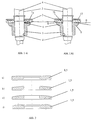
- the axial bearings shown in Figures 1 a) and 1 b) consist of an annular planar plain bearing part 1, which is made of ceramic and thus has a very high wear resistance.
- This slide bearing part 1, which is designed as a sliding disk, is connected in a rotationally fixed manner to the shaft 3 via a holder 2 and rotates with the shaft 3 about the axis of rotation 4.
- a bush-shaped plain bearing part 5 is used as a counter bearing to the above-mentioned plain bearing part 1, to which a flange 6 is formed, the one lateral surface of which is the sliding surface of the counter bearing.
- This plain bearing part 5 is made of resin-impregnated carbon, which has a lower wear resistance than ceramic.
- the slide bearing part 5 contains an opening 11 for the play-free rotatable reception of the shaft 3 and is connected in a rotationally fixed manner to a holder, not shown, for example that of a motor shaft.
- both slide bearing parts 1 and 5 have plane-parallel sliding surfaces and the contact surface corresponds to the maximum ring surface 7a, which is given by the inner and outer diameter of the carbon sliding bearing part 5 .
- Figure 2 a) shows a cross section of the flat sliding surface of the ceramic sliding bearing part 1 or the carbon sliding bearing part 2 according to the prior art.
- Figure 1 b shows a thrust bearing according to the invention.
- the sliding surface of the carbon sliding bearing part 5 has a conical shape in which the material thickness, based on the sliding bearing rear surface 9, decreases from the inner edge to the outer edge.
- the sliding surface formed in this way forms an angle ⁇ of 1 to 10 degrees, in particular 5 degrees, with the flat sliding surface of the ceramic sliding bearing part 1, which lies in a plane perpendicular to the axis of rotation 4.
- the two sliding surfaces of the sliding bearing parts 1 and 5 lie against one another only at an annular contact line 7b.
- this line of contact 7b will become an annular from the inner to the outer edge of the sliding surface Increase the contact area. This enlargement takes place automatically as a function of the axially acting force due to wear of the sliding surface of the carbon plain bearing part 5.
- FIG. 2 c) shows the cross section of a sliding surface which, based on the entire diameter, is convex due to a large radius.
- this convex shape has the advantage that a larger contact surface is achieved more quickly due to wear and therefore the relative wear-related displacement of the two slide bearing parts relative to one another, based on the sliding surface rear sides 9 and 10, is less.
- Figure 2 d shows the cross section of a sliding surface that is only convex between the inner edge and the outer edge. Viewed in cross-section, this geometry has the greatest height between the two bearing edges. Here, too, the contact area will increase faster than with the conical design under heavy axial loads.
Landscapes
- Engineering & Computer Science (AREA)
- General Engineering & Computer Science (AREA)
- Mechanical Engineering (AREA)
- Chemical & Material Sciences (AREA)
- Ceramic Engineering (AREA)
- Oil, Petroleum & Natural Gas (AREA)
- Physics & Mathematics (AREA)
- Fluid Mechanics (AREA)
- Structures Of Non-Positive Displacement Pumps (AREA)
- Sliding-Contact Bearings (AREA)
Abstract
Die Erfindung betrifft ein Axiallager, insbesondere einer Spaltrohrmotorkreiselpumpe, bestehend aus einem rotierenden und einem stillstehenden Gleitlagerteil, die unterschiedliche Verschleißfestigkeit und jeweils eine seitliche Gleitfläche aufweisen, wobei die Gleitfläche des einen Gleitlagerteils zur Gleitfläche des anderen Gleitlagerteils am Außen- und/oder Innenrand oder zwischen diesen Rändern einen Abstand, insbesondere einen Spalt bildet.
Description
Die Erfindung betrifft ein Axiallager, das zur Aufnahme von Axialkräften eingesetzt wird, die insbesondere bei Pumpenmotoren auftreten. Für Naßläufermotoren, die z.B. in Spaltrohrmotorpumpen eingesetzt werden, kommen sogenannte Gleitlager zum Einsatz, bei denen sich zwischen dem bewegten und dem ruhenden Gleitlagerteil eine flüssige Zwischenschicht befindet.The invention relates to an axial bearing which is used to absorb axial forces which occur in particular in pump motors. For wet rotor motors, e.g. In canned motor pumps, so-called plain bearings are used, in which there is a liquid intermediate layer between the moving and the stationary plain bearing part.
Diese Zwischenschicht bewirkt einen stabilen und weitgehend verschleißfreien Betrieb des Gleitlagers und wird durch das geförderte Mittel, das den Motorläufer umspült, selbst gebildet. Da obengenannte Pumpen meistens für die Förderung von Wasser verwendet werden, wird diese schmierende flüssige Schicht zwischen den beiden Lagerteilen durch das Wasser gebildet.This intermediate layer ensures stable and largely wear-free operation of the plain bearing and is itself formed by the funded agent that washes around the motor rotor. Since the pumps mentioned above are mostly used for the conveyance of water, this lubricating liquid layer is formed by the water between the two bearing parts.
In diesem Anwendungsfall werden Gleitlager gegenüber Wälzlagern vorgezogen, weil sie sich durch hohe Belastbarkeit, große Laufruhe und nahezu verschleißfreien Betrieb auszeichnen. Darüber hinaus haben derartige Gleitlager ein kleineres Bauvolumen und einen geringeren Herstellungspreis.In this application, plain bearings are preferred to roller bearings because they are characterized by high resilience, smooth running and almost wear-free operation. In addition, such plain bearings have a smaller construction volume and a lower manufacturing price.
In der Praxis hat es sich herausgestellt, daß unter ungünstigen Umständen die Axiallager blockieren können. Ein solcher Fall kann zum Beispiel auftreten, wenn die Pumpe längere Zeit nicht in Betrieb war und dadurch die Lager ausgetrocknet sind. Weiterhin kann es vorkommen, daß Motorschutzeinrichtungen die Pumpe bei einer erhöhten Stromaufnahme abschalten, die sich bei einer vergrößerten Lagerreibung ergibt.In practice, it has been found that the axial bearings can lock under unfavorable circumstances. Such a case can occur, for example, if the pump has not been in operation for a long time and the bearings have dried up as a result. Furthermore, it can happen that motor protection devices switch off the pump when there is an increased current consumption, which results in an increased bearing friction.
Für den bisherigen Aufbau solcher Gleitlager werden üblicherweise zwei Gleitlagerteile aus verschiedenen Materialien eingesetzt, wobei eines der Materialien gegenüber dem anderen eine geringere Verschleißfestigkeit aufweist.For the previous construction of such plain bearings, two plain bearing parts made of different materials are usually used, one of the materials being less wear-resistant than the other.
Als Materialien kommen hier insbesondere Keramik und Kohle zum Einsatz. Obengenannte Axiallager werden so aufgebaut, daß ein Gleitlagerteil rotiert und das andere stillsteht. Hierbei wird als rotierendes Gleitlagerteil eine Gleitscheibe aus Keramik benutzt. Das stillstehende Gleitlagerteil wird aus Kohle aufgebaut, wobei in die Gleitfläche für eine bessere Schmierung mehrere Nute in radialer Richtung eingearbeitet sein können.In particular, ceramics and coal are used as materials. Above-mentioned thrust bearings are constructed so that one plain bearing part rotates and the other stands still. A ceramic sliding washer is used as the rotating slide bearing part. The stationary slide bearing part is made of coal, and several grooves can be machined in the radial direction for better lubrication.
Beide eingesetzte Gleitlagerteile haben nahezu identisch große Gleitflächen die einander planparallel gegenüberliegen und sich auch während des Betriebes durch Verschleiß in Größe und Lage nicht ändern. Ein derartiges Lager ist in der Abbildung 1 a) dargestellt. Die Abbildung 2 a) zeigt im Querschnitt die als Gleitlagerteil verwendete Gleitscheibe aus Keramik, die die gleiche plane Gleitfläche aufweist, wie das Gleitlagerteil aus Kohle.Both slide bearing parts used have almost identical sliding surfaces which are opposite to each other plane-parallel and do not change in size and position even during operation due to wear. Such a bearing is shown in Figure 1 a). Figure 2 a) shows a cross-section of the ceramic sliding washer used as a sliding bearing part, which has the same flat sliding surface as the carbon sliding bearing part.
Die Blockierneigung eines Gleitlagers ist maßgeblich durch die Größe der sich berührenden Gleitflächen gegeben ist. Eine Verringerung der Blockierneigung kann daher nur durch eine Größenreduzierung dieser sich berührenden Gleitflächen erreicht werden.The tendency of a plain bearing to lock is largely determined by the size of the contacting sliding surfaces. A reduction in the tendency to lock can therefore only be achieved by reducing the size of these contacting sliding surfaces.
Aufgabe der Erfindung ist es, ein aus zwei Gleitlagerteilen bestehendes Axiallager zu schaffen, das sich durch eine wesentlich verringerte Gleitfläche auszeichnet, die sich im Bedarfsfall bei erhöhten Axialkräften durch verschleißbedingte Vergrößerung selbsttätig auf die erforderliche Gleitflächengröße einstellt.The object of the invention is to provide a thrust bearing consisting of two slide bearing parts, which is characterized by a substantially reduced sliding surface, which adjusts itself automatically to the required sliding surface size if required, with increased axial forces due to wear-related enlargement.
Diese Aufgabe wird erfindungsgemäß durch ein Axiallager nach Patentanspruch 1 gelöst. Das erfindungsgemäße Axiallager hebt sich gegenüber dem bisher verwendeten Axialager dadurch ab, daß die Gleitfläche des einen Gleitlagerteils zur Gleitfläche des anderen Gleitlagerteils am Außen- und/oder Innenrand oder zwischen diesen Rändern einen Abstand, insbesondere einen Spalt bildet.This object is achieved by an axial bearing according to
Ein derartiges Axiallager hat den Vorteil, daß sich zwischen den sich gegenüberliegenden Gleitflächen eine kleinere Berührungsfläche ergibt als bei einen Axiallager der bisherigen Art. Wegen der hierdurch bedingten geringeren Reibung zwischen den Gleitflächen wird eine Reduzierung der Blockierneigung des Lagers erreicht. Die Verringerung der Berührungsfläche wirkt sich insbesondere dann positiv aus, wenn die Pumpe längere Zeit stillstand und das Lager ausgetrocknet ist.Such an axial bearing has the advantage that there is a smaller contact area between the opposing sliding surfaces than in the case of an axial bearing of the previous type. Because of the resulting lower friction between the sliding surfaces, a reduction in the tendency of the bearing to lock is achieved. The reduction in the contact area has a particularly positive effect if the pump has been idle for a long time and the bearing has dried out.
Der am Außen- und/oder Innenrand der Gleitfläche gebildete Spalt bewirkt zusätzlich bei dem erfindungsgemäßen Axiallager ein leichteres Eindringen der schmierenden Flüssigkeit zwischen die Gleitflächen des Axiallagers, wodurch gegenüber dem ursprünglichen Axiallager ein insgesamt geringerer Verschleiß erreicht wird.The gap formed on the outer and / or inner edge of the sliding surface additionally causes in the axial bearing according to the invention an easier penetration of the lubricating liquid between the sliding surfaces of the axial bearing, whereby overall less wear is achieved compared to the original axial bearing.
Vorteilhafterweise wird das Axiallager so aufgebaut, daß die Gleitflächen der beiden Gleitlagerteile vor ihrer Benutzung in einer ringförmigen Berührungslinie aneinanderliegen. Diese ringförmige Berührungslinie ist abhängig von der wirkenden Axialkraft bis auf eine maximale mögliche ringförmige Berührungsfläche durch Verschleiß selbsttätig vergrößerbar.The axial bearing is advantageously constructed in such a way that the sliding surfaces of the two sliding bearing parts lie against one another in an annular line of contact before they are used. This ring-shaped line of contact can be increased by wear depending on the axial force acting up to a maximum possible ring-shaped contact area.
Hierdurch ergibt sich, daß die erfindungsgemäßen Axiallager für die unterschiedlichsten Pumpen universell einsetzbar sind, da sich je nach axialer Belastung die benötigte Berührungsfläche selbsttätig einstellt. Erst unter maximaler Belastung wird der Verschleiß so groß sein, daß sich im Betrieb des Lagers eine Berührungsfläche ergibt, die so groß ist, wie bei den ursprünglichen Axiallagern. Diese maximale Berührungsfläche ist so dimensioniert, daß selbst bei Dauerversuchspumpen kein weiterer wesentlicher Verschleiß feststellbar ist.As a result, the axial bearings according to the invention can be used universally for a wide variety of pumps, since the required contact surface is set automatically depending on the axial load. Only under maximum load will the wear be so great that there is a contact surface during operation of the bearing that is as large as that of the original thrust bearings. This maximum contact area is dimensioned such that no further significant wear can be determined even in long-term test pumps.
Bevorzugt werden die Gleitlagerteile so ausgeführt, daß eines eine geringere Verschleißfestigkeit aufweist als das andere. Insbesondere werden als Materialien Keramik und kunstharzimprägnierte Kohle gewählt. Bei dieser Materialwahl wird der beabsichtigte selbsttätige Verschleiß im wesentlichen nur bei dem aus Kohle gefertigten Gleitlagerteil stattfinden. Dementsprechend wird, wie bei dem ursprünglichen Axiallager nach dem Stand der Technik, als ein Gleitlagerteil eine rotierende plane ringförmige Gleitscheibe aus Keramik verwendet. Das feststehende Gleitlagerteil ist aus Kohle gefertigt und besitzt eine modifizierte Gleitfläche.The plain bearing parts are preferably designed so that one has a lower wear resistance than the other. In particular, ceramics and resin-impregnated coal are chosen as materials. With this choice of material, the intended automatic wear will essentially only take place with the plain bearing part made of coal. Accordingly, as in the original axial bearing according to the prior art, a rotating, flat, annular sliding disk made of ceramic is used as a sliding bearing part. The fixed plain bearing part is made of coal and has a modified sliding surface.
Bei einem derartigen Axiallager sind die Vorteile insbesondere darin zu sehen, daß die Gleitflächenbeschaffenheit so ist, wie bei dem ursprünglichen Lager, für das gute Erfahrungswerte vorliegen, die sich berührenden Flächenteile planparallel zueinander liegen, durch die Selbsteinstellung die Berührungsfläche nur die eben erforderliche Größe erreicht und dadurch die Blockierneigung reduziert wird, schlimmstenfalls eine maximale Berührungsfläche zur Verfügung steht, in der Einlaufphase des Lagers keine erhöhte Stromaufnahme meßbar ist und letztendlich ein derartiges erfindungsgemäßes Lager sehr kostengünstig herstellbar ist.With such a thrust bearing, the advantages can be seen in particular in the fact that the sliding surface is like the original bearing, for which good empirical values are available, the contacting surface parts are plane-parallel to each other, the contact surface only reaches the size required by the self-adjustment and this reduces the tendency to block, in the worst case a maximum contact area is available, in the running-in phase of the bearing no increased current consumption can be measured and in the end such a bearing according to the invention can be produced very inexpensively.
Bei dem erfindungsgemäßen Axiallager ist es vorgesehen, die Gleitfläche des Gleitlagerteils aus Kohle, bezogen auf den gesamten Durchmesser der Gleitfläche, konisch, konvex oder konkav auszubilden.In the axial bearing according to the invention it is provided that the sliding surface of the sliding bearing part is made of carbon, based on the entire diameter of the sliding surface, conical, convex or concave.
Bei der konischen Gleitfläche fällt die Materialstärke des Gleitlagerteils aus Kohle, bezogen auf die Gleitlagerrückfläche, in einer gleichmäßigen Schräge mit konstanter Steigung vom inneren Rand des Gleitlagers zum äußeren Rand ab. Hierdurch wird bewirkt, daß sich die Berührungsfläche während der Benutzung des Axiallagers durch Verschleiß von innen nach außen vergrößert.In the case of the conical sliding surface, the material thickness of the slide bearing part made of carbon, in relation to the slide bearing back surface, drops in a uniform slope with a constant slope from the inner edge of the slide bearing to the outer edge. This has the effect that the contact surface increases during wear of the thrust bearing from the inside to the outside.
Ebenso ist es denkbar, eine konische Gleitfläche des Kohle-Gleitlagerteils herzustellen, bei dem die Materialstärke vom inneren Rand zum äußeren Rand zunimmt. In diesem Fall wird der obengenannte Spalt zwischen den beiden Gleitflächen am inneren Rand des Lagers gebildet und die Berührungsfläche vergrößert sich von außen nach innen.It is also conceivable to produce a conical sliding surface of the carbon plain bearing part, in which the material thickness increases from the inner edge to the outer edge. In this case, the above-mentioned gap is formed between the two sliding surfaces on the inner edge of the bearing and the contact surface increases from the outside to the inside.
In weiteren Ausführungsformen wird die Gleitfläche des Gleitlagerteils aus Kohle z.B. mit einem großen Radius versehen, so daß sich, wiederum bezogen auf den gesamten Durchmesser, eine konvexe Gleitfläche des Lagers ergibt. Gegenüber der konischen Form der Gleitfläche hat diese Gestaltung den Vorteil, daß sich die Berührungslinie durch Verschleiß schneller auf eine größere Fläche einstellt, ohne daß sich die axiale Lage des Gleitlagerteils stark verändert. Die Lageänderung aufgrund des selbsttätigen Verschleißes liegt bei etwa 1-2 mm. Auch bei dieser Ausgestaltung bildet sich ein Spalt am äußeren Rand der Gleitfläche und die Berührungsfläche vergrößert sich durch Verschleiß von innen nach außen.In further embodiments, the sliding surface of the plain bearing part made of coal e.g. provided with a large radius, so that, again based on the entire diameter, there is a convex sliding surface of the bearing. Compared to the conical shape of the sliding surface, this design has the advantage that the line of contact adjusts to a larger area more quickly due to wear and tear, without the axial position of the sliding bearing part changing significantly. The change in position due to automatic wear is about 1-2 mm. In this embodiment too, a gap is formed on the outer edge of the sliding surface and the contact surface increases due to wear from the inside to the outside.
Ebenso ist es möglich die Gleitfläche konkav auszugestalten. Hier wiederum bildet sich der Spalt am inneren Rand der Gleitflächen und die Berührungsfläche vergrößert sich von außen nach innen.It is also possible to make the sliding surface concave. Here, in turn, the gap forms on the inner edge of the sliding surfaces and the contact surface increases from the outside inwards.
Eine ebenfalls vorteilhafte Ausgestaltung des Axiallagers ist darin zu sehen, daß die Gleitfläche des Gleitlagerteils aus Kohle zwischen dem inneren Rand und dem äußeren Rand der Gleitfläche konisch, konvex oder konkav ausgebildet ist. In den ersten beiden Fällen zeigt die Gleitfläche zwischen innerem und äußerem Rand die größte Materialstärke. Bei diesen Ausgestaltungen vergrößert sich die Berührungsfläche dann in beiden Richtungen ausgehend von einer Berührungslinie. Ein Spalt wird sowohl am inneren als auch am äußeren Rand der Gleitfläche gebildet.Another advantageous embodiment of the thrust bearing can be seen in the fact that the sliding surface of the sliding bearing part made of carbon is conical, convex or concave between the inner edge and the outer edge of the sliding surface. In the first two cases, the sliding surface between the inner and outer edge shows the greatest material thickness. In these configurations, the contact area then increases in both directions, starting from a line of contact. A gap is formed on both the inner and the outer edge of the sliding surface.
Im konkaven Fall ist die Materialstärke am inneren und äußeren Rand der Gleitfläche am größten und die beiden einander gegenüberliegenden Gleitflächen bilden zwischen innerem und äußerem Rand einen Abstand oder Spalt. Bei dieser Gestaltung vergrößert sich die Berührungsfläche ausgehend von zwei ringförmigen Berührungslinien.In the concave case, the material thickness is greatest at the inner and outer edge of the sliding surface and the two opposing sliding surfaces form a distance or gap between the inner and outer edge. With this design, the contact area increases from two annular contact lines.
Jede der hier vorgestellten Gleitflächengeometrien ist herstellbar. Weiterhin ist es möglich andere hier nicht vorgestellte Gleitflächengeometrien herzustellen, die ebenfalls eine örtlich variable Gleitflächendicke aufweisen.Any of the sliding surface geometries presented here can be manufactured. Furthermore, it is possible to produce other sliding surface geometries which are not presented here and which also have a locally variable sliding surface thickness.
In einer weiteren Ausführungsform des Axiallagers ist es möglich, nicht das Gleitlagerteil aus Kohle in seiner Gleitflächenform zu verändern und das Gleitlagerteil aus Keramik plan zu belassen, sondern vielmehr umgekehrt, das Gleitlagerteil aus Keramik in seiner Gleitflächengeometrie zu ändern und das verschleißende Gleilagerteil aus Kohle plan zu belassen. Für das zu ändernde Gleitlagerteil aus Keramik gelten in diesem Fall die obigen Ausführungen genauso wie für das Gleitlagerteil aus Kohle.In a further embodiment of the thrust bearing, it is possible not to change the plain bearing part made of coal in its sliding surface shape and to leave the ceramic plain bearing part flat, but rather vice versa, to change the sliding surface part made of ceramic in its sliding surface geometry and to planar the wearing plain bearing part made of coal leave. In this case, the above explanations apply to the slide bearing part made of ceramic as well as for the slide bearing part made of carbon.
Weiterhin kann ein Axiallager hergestellt werden, bei dem nicht nur eines, sondern beide Gleitlagerteile eine der oben beschriebenen Gleitflächengeometrien aufweisen.Furthermore, an axial bearing can be produced in which not only one but both slide bearing parts have one of the slide surface geometries described above.
Diese verschiedenen Gleitflächengeometrien sind auch maßgeblich dafür verantwortlich, welcher Abstand sich nach dem Einlaufen des Axiallagers insbesondere zwischen den beiden Gleitlagerrückflächen einstellt und um welche Strecke sich somit z.B. der Läufer eines Motors versetzt. Wie bereits weiter oben dargelegt, muß bei der konischen Form, um eine größere Berührungsfläche zu erhalten, mehr Material abgetragen werden, als bei der konvexen durch einen Radius gegebenen Gleitfläche.These different sliding surface geometries are also largely responsible for the distance that occurs after the axial bearing has run in, in particular between the two sliding bearing rear surfaces, and the distance by which e.g. the rotor of a motor displaced. As already explained above, in the case of the conical shape, in order to obtain a larger contact area, more material has to be removed than in the case of the convex sliding surface given by a radius.
Darüber hinaus ist eine Ausführungsform des Axiallagers möglich, bei dem nicht das verschleißende Gleilagerteil stillsteht und sich das andere Gleitlagerteil dreht, sondern umgekehrt das verschleißende Gleitlagerteil sich dreht und das verschleißfestere Teil stillsteht.In addition, an embodiment of the thrust bearing is possible in which the wearing plain bearing part does not stand still and the other plain bearing part rotates, but, conversely, the wearing plain bearing part rotates and the more wear-resistant part stands still.
Aus Kosten- und Herstellungsgründen ist die Ausführungsform zu bevorzugen, bei der die plane Form des rotierenden Gleitlagerteils aus Keramikl beibehalten wird. Hier wird also nur die Gleitfläche des stillstehenden Gleitlagerteils aus Kohle modifiziert.For reasons of cost and production, the embodiment is preferred in which the plane shape of the rotating ceramic bearing part is maintained. So here only the sliding surface of the stationary plain bearing part made of coal is modified.
Bei dieser letztgenannten Ausführungsform ergibt sich ein Einlaufverhalten des Axiallagers, das mit dem des ursprünglichen Axiallagers identisch ist, die Blockierneigung der Pumpe ist deutlich reduziert und das Lager zeigt ein verbessertes Trockenlauf- und Verschleißverhalten. Unter ungünstigsten Umständen kann sich durch die Selbsteinstellung des Axiallagers die Gleitfläche des ursprünglich verwendeten Lagers wieder einstellen.In this latter embodiment, the thrust behavior of the thrust bearing is identical to that of the original thrust bearing, the tendency of the pump to lock is significantly reduced and the bearing exhibits improved dry running and wear behavior. In the worst circumstances, the sliding surface of the bearing originally used can be restored by the self-adjustment of the thrust bearing.
Der Stand der Technik und ein Ausführungsbeispiel der Erfindung ist in den Zeichnungen dargestellt und wird im folgenden näher beschrieben.The prior art and an embodiment of the invention is shown in the drawings and will be described in more detail below.
Es zeigen:
- Abbildung 1 a):
- einen axialen Schnitt durch das Axiallager nach dem Stand der Technik.
- Abbildung 1 b):
- einen axialen Schnitt durch das Axiallager gemäß der Erfindung.
- Abbildung 2 a):
- einen Querschnitt durch ein Gleitlagerteil mit planer Gleitfläche nach dem Stand der Technik.
- Abbildung 2 b):
- einen Querschnitt durch ein erfindungsgemäßes Gleitlagerteil mit konischer Gleitfläche, bezogen auf den gesamten Durchmesser der Gleitfläche
- Abbildung 2 c):
- einen Querschnitt durch ein erfindungsgemäßes Gleitlagerteil mit konvexer Gleitfläche, bezogen auf den gesamten Durchmesser der Gleitfläche.
- Abbildung 2 d):
- einen Querschnitt durch ein erfindungsgemäßes Gleitlagerteil mit konvexer Gleitfläche zwischen innerem und äußerem Rand der Gleitfläche.
- Figure 1 a):
- an axial section through the thrust bearing according to the prior art.
- Figure 1 b):
- an axial section through the thrust bearing according to the invention.
- Figure 2 a):
- a cross section through a plain bearing part with a flat sliding surface according to the prior art.
- Figure 2 b):
- a cross section through an inventive plain bearing part with a conical sliding surface, based on the entire diameter of the sliding surface
- Figure 2 c):
- a cross section through an inventive plain bearing part with a convex sliding surface, based on the entire diameter of the sliding surface.
- Figure 2 d):
- a cross section through an inventive plain bearing part with a convex sliding surface between the inner and outer edge of the sliding surface.
Die in den Abbildungen 1 a) und 1 b) dargestellten Axiallager bestehen aus einem ringförmigen planen Gleitlagerteil 1, das aus Keramik hergestellt ist und somit eine sehr hohe Verschleißfestigkeit aufweist. Dieses als Gleitscheibe ausgebildete Gleitlagerteil 1 ist über eine Halterung 2 mit der Welle 3 drehfest verbunden und dreht sich mit der Welle 3 um die Drehachse 4.The axial bearings shown in Figures 1 a) and 1 b) consist of an annular planar
Als Gegenlager zu dem obengenannten Gleitlagerteil 1 wird ein buchsenförmiges Gleitlagerteil 5 verwendet, an das ein Flansch 6 angeformt ist, dessen eine seitliche Fläche die Gleitfläche des Gegenlagers bildet. Dieses Gleitlagerteil 5 wird aus kunstharzimpränierter Kohle hergestellt, die eine geringere Verschleißfestigkeit aufweist als Keramik. Das Gleitlagerteil 5 enthält eine Öffnung 11 zur spielfreien drehbaren Aufnahme der Welle 3 und wird drehfest mit einer nicht dargestellten Halterung, z.B. die einer Motorwelle, verbunden.A bush-shaped
Bei dem Axiallager nach dem Stand der Technik, das in der Abbildung 1 a) dargestellt ist, haben beide Gleitlagerteile 1 und 5 planparallele Gleitflächen und die Berührfläche entspricht der maximalen Ringfläche 7a, die durch den inneren und äußeren Durchmesser des Kohle-Gleitlagerteils 5 gegeben ist. In der Abbildung 2 a) ist im Querschnitt die plane Gleitfläche des Keramik-Gleitlagerteils 1 bzw. des Kohle-Gleitlagerteils 2 nach dem Stand der Technik dargestellt.In the axial bearing according to the prior art, which is shown in Figure 1 a), both slide bearing
Die Abbildung 1 b) zeigt ein Axiallager gemäß der Erfindung. Die Gleitfläche des Kohle-Gleitlagerteils 5 besitzt eine konische Form, bei der die Materialstärke, bezogen auf die Gleitlagerrückfläche 9, vom inneren Rand zum äußeren Rand abnimmt. Die so gebildete Gleitfläche bildet mit der planen Gleitfläche des keramischen Gleitlagerteils 1, die in einer zur Drehachse 4 senkrechten Ebene liegt, einen Winkel α von 1 bis 10 Grad, insbesondere 5 Grad.Figure 1 b) shows a thrust bearing according to the invention. The sliding surface of the carbon sliding bearing
Diese Form der Gleitfläche ist im Querschnitt in der Abbildung 2 b) dargestellt. Hierdurch bildet sich am äußeren Rand zwischen den Gleitflächen der Gleitlagerteile 1 und 5 ein Spalt 8, der ein besseres Eindringen der Schmierflüssigkeit zwischen die Gleitflächen ermöglicht.This shape of the sliding surface is shown in cross section in Figure 2 b). As a result, a
Vor der Benutzung des erfindungsgemäßen Axiallagers liegen die beiden Gleitflächen der Gleitlagerteile 1 und 5 nur an einer ringförmigen Berührungslinie 7b aneinander. Während der Benutzung des Lagers wird sich diese Berührungslinie 7b vom inneren zum äußeren Rand der Gleitfläche zu einer ringförmigen Berührungsfläche vergrößern. Diese Vergrößerung erfolgt selbsttätig in Abhängigkeit von der axial wirkenden Kraft aufgrund eines Verschleißes der Gleitfläche des Kohle-Gleitlagerteils 5.Before the axial bearing according to the invention is used, the two sliding surfaces of the sliding
Die Abbildung 2 c) zeigt in einer weiteren Ausführungsform den Querschnitt eine Gleitfläche, die, bezogen auf den gesamten Durchmesser, durch einen großen Radius konvex ausgebildet ist. Gegenüber der konischen Form hat diese konvexe Form den Vorteil, daß durch den Verschleiß schneller eine größere Berührungsfläche erzielt wird und daher die relative verschleißbedingte Verschiebung der beiden Gleitlagerteile zueinander, bezogen auf die Gleitflächenrückseiten 9 und 10 geringer ausfällt.In a further embodiment, FIG. 2 c) shows the cross section of a sliding surface which, based on the entire diameter, is convex due to a large radius. Compared to the conical shape, this convex shape has the advantage that a larger contact surface is achieved more quickly due to wear and therefore the relative wear-related displacement of the two slide bearing parts relative to one another, based on the sliding surface
Abbildung 2 d) zeigt den Querschnitt einer Gleitfläche, die nur zwischen dem inneren Rand und dem äußeren Rand konvex ausgebildet ist. Diese Geometrie hat im Querschnitt betrachtet zwischen beiden Lagerrändern die größte Höhe. Auch hier wird sich bei starker axialer Belastung die Berührungsfläche schneller vergrößern als bei der konischen Bauform.Figure 2 d) shows the cross section of a sliding surface that is only convex between the inner edge and the outer edge. Viewed in cross-section, this geometry has the greatest height between the two bearing edges. Here, too, the contact area will increase faster than with the conical design under heavy axial loads.
Claims (8)
Applications Claiming Priority (2)
| Application Number | Priority Date | Filing Date | Title |
|---|---|---|---|
| DE1996118767 DE19618767A1 (en) | 1996-05-10 | 1996-05-10 | Self-adjusting axial bearing for high pressure centrifugal pumps |
| DE19618767 | 1996-05-10 |
Publications (2)
| Publication Number | Publication Date |
|---|---|
| EP0806579A2 true EP0806579A2 (en) | 1997-11-12 |
| EP0806579A3 EP0806579A3 (en) | 1998-09-09 |
Family
ID=7793889
Family Applications (1)
| Application Number | Title | Priority Date | Filing Date |
|---|---|---|---|
| EP97107718A Withdrawn EP0806579A3 (en) | 1996-05-10 | 1997-05-12 | Self-aligning axial bearing |
Country Status (2)
| Country | Link |
|---|---|
| EP (1) | EP0806579A3 (en) |
| DE (1) | DE19618767A1 (en) |
Cited By (8)
| Publication number | Priority date | Publication date | Assignee | Title |
|---|---|---|---|---|
| EP1201931A3 (en) * | 2000-10-23 | 2005-06-08 | TM.P. S.p.A. Termomeccanica Pompe | Sliding-contact bearing for a centrifugal pump |
| DE102005019984A1 (en) * | 2005-04-27 | 2006-11-09 | A. Friedr. Flender Ag | plain bearing |
| WO2007031662A1 (en) * | 2005-09-16 | 2007-03-22 | Renault S.A.S. | Motor vehicle gearbox provided with a hydrodynamic axial thrust bearing, and related hydrodynamic axial thrust bearing |
| DE102011075227A1 (en) * | 2011-05-04 | 2012-11-08 | BSH Bosch und Siemens Hausgeräte GmbH | Thrust bearing for an electric drive |
| CN102878105A (en) * | 2012-07-16 | 2013-01-16 | 晋州市水泵厂 | Self-aligning thrust bearing for submerged pump |
| DE102016007862A1 (en) | 2016-06-29 | 2018-01-04 | Wilo Se | Axial plain bearing |
| CN107795510A (en) * | 2017-11-24 | 2018-03-13 | 湖州三井低温设备有限公司 | A kind of more grade low-temp immersed pump axial force balance mechanisms |
| CN113339313A (en) * | 2021-07-08 | 2021-09-03 | 哈尔滨电气动力装备有限公司 | Centrifugal adjusting method for odd asymmetric radial tile gaps of shaft seal type nuclear main pump |
Families Citing this family (4)
| Publication number | Priority date | Publication date | Assignee | Title |
|---|---|---|---|---|
| DE10028951A1 (en) * | 2000-06-16 | 2002-01-03 | Grundfos As | Axial sliding bearing for a wet running centrifugal pump |
| DE10140613A1 (en) * | 2001-08-18 | 2003-03-06 | Pierburg Gmbh | Naßläuferpumpe |
| DE102016202417A1 (en) * | 2016-02-17 | 2017-08-17 | Bühler Motor GmbH | rotary pump |
| DE102016006271A1 (en) | 2016-05-25 | 2017-11-30 | Wilo Se | Axial error compensation by means of balancing mass |
Family Cites Families (6)
| Publication number | Priority date | Publication date | Assignee | Title |
|---|---|---|---|---|
| US2953416A (en) * | 1957-09-17 | 1960-09-20 | Garrett Corp | Thrust bearing construction |
| US3090655A (en) * | 1960-10-14 | 1963-05-21 | Gen Motors Corp | Thrust bearing |
| FR1531092A (en) * | 1967-07-12 | 1968-06-28 | Skf Kugellagerfabriken Gmbh | Thrust bearing, in particular for stub axles |
| FR2126511A5 (en) * | 1971-02-09 | 1972-10-06 | Commissariat Energie Atomique | |
| DE3140017A1 (en) * | 1981-10-08 | 1983-04-28 | Flender A F Gmbh Co Kg | Hydrodynamic sliding-contact thrust bearing |
| JPH01176812A (en) * | 1987-12-28 | 1989-07-13 | Taiho Kogyo Co Ltd | Motor bearing device |
-
1996
- 1996-05-10 DE DE1996118767 patent/DE19618767A1/en not_active Withdrawn
-
1997
- 1997-05-12 EP EP97107718A patent/EP0806579A3/en not_active Withdrawn
Cited By (15)
| Publication number | Priority date | Publication date | Assignee | Title |
|---|---|---|---|---|
| EP1201931A3 (en) * | 2000-10-23 | 2005-06-08 | TM.P. S.p.A. Termomeccanica Pompe | Sliding-contact bearing for a centrifugal pump |
| DE102005019984A1 (en) * | 2005-04-27 | 2006-11-09 | A. Friedr. Flender Ag | plain bearing |
| WO2007031662A1 (en) * | 2005-09-16 | 2007-03-22 | Renault S.A.S. | Motor vehicle gearbox provided with a hydrodynamic axial thrust bearing, and related hydrodynamic axial thrust bearing |
| FR2891034A1 (en) * | 2005-09-16 | 2007-03-23 | Renault Sas | GEARBOX FOR A MOTOR VEHICLE COMPRISING A HYDRODYNAMIC AXIAL FASTENING, AND A AXIAL HYDRODYNAMIC FASTENER THEREFOR. |
| CN103503284A (en) * | 2011-05-04 | 2014-01-08 | Bsh博世和西门子家用电器有限公司 | Axial bearing for an electric drive |
| DE102011075227A1 (en) * | 2011-05-04 | 2012-11-08 | BSH Bosch und Siemens Hausgeräte GmbH | Thrust bearing for an electric drive |
| US20140072459A1 (en) * | 2011-05-04 | 2014-03-13 | Michal Kalavsky | Axial bearing for an electric drive |
| US9702370B2 (en) | 2011-05-04 | 2017-07-11 | Bsh Hausgeraete Gmbh | Axial bearing for an electric drive |
| CN102878105A (en) * | 2012-07-16 | 2013-01-16 | 晋州市水泵厂 | Self-aligning thrust bearing for submerged pump |
| CN102878105B (en) * | 2012-07-16 | 2015-04-22 | 晋州市水泵厂 | Self-aligning thrust bearing for submerged pump |
| DE102016007862A1 (en) | 2016-06-29 | 2018-01-04 | Wilo Se | Axial plain bearing |
| CN107795510A (en) * | 2017-11-24 | 2018-03-13 | 湖州三井低温设备有限公司 | A kind of more grade low-temp immersed pump axial force balance mechanisms |
| CN107795510B (en) * | 2017-11-24 | 2024-03-22 | 湖州三井低温设备有限公司 | Axial force balance mechanism of multistage low-temperature immersed pump |
| CN113339313A (en) * | 2021-07-08 | 2021-09-03 | 哈尔滨电气动力装备有限公司 | Centrifugal adjusting method for odd asymmetric radial tile gaps of shaft seal type nuclear main pump |
| CN113339313B (en) * | 2021-07-08 | 2022-07-22 | 哈尔滨电气动力装备有限公司 | Centrifugal adjusting method for odd asymmetric radial tile gaps of shaft seal type nuclear main pump |
Also Published As
| Publication number | Publication date |
|---|---|
| EP0806579A3 (en) | 1998-09-09 |
| DE19618767A1 (en) | 1997-11-13 |
Similar Documents
| Publication | Publication Date | Title |
|---|---|---|
| EP0158242B1 (en) | Sliding contact bearing for radial load | |
| DE1675076C2 (en) | Hydrodynamic bearing to absorb axial and radial loads | |
| DE1525198C3 (en) | Hydrodynamic plain bearing | |
| DE2624849C3 (en) | Self-pressure generating radial plain bearing | |
| DE69007079T2 (en) | Bushing for oil film bearings. | |
| EP0023657B1 (en) | Hydrodynamic bearing | |
| WO2000043688A1 (en) | Buffer disk of a planetary drive | |
| EP0806579A2 (en) | Self-aligning axial bearing | |
| DE1525193A1 (en) | Training and assignment of warehouse parts | |
| DE10158768B4 (en) | Radial piston pump | |
| DE4303050B4 (en) | Mechanical seal | |
| DE4214936A1 (en) | PIVOT TYPE TRACK ROLLER BEARING | |
| DE102012016983B4 (en) | Rolling bearing with rolling bearing cage | |
| DE102016205896A1 (en) | Bearing and bearing arrangement | |
| EP3434917A1 (en) | Bearing arrangement for mounting a transmission shaft | |
| EP4067706B1 (en) | Sealing ring | |
| DE1286344B (en) | Radial roller bearings | |
| DE2731313A1 (en) | FLEXIBLE SEAL AND SEAL CONSTRUCTION | |
| DE3925404A1 (en) | Dry gas seal for machine shaft - has aerodynamic lubrication with safeguard against running dry | |
| EP2535606B1 (en) | Axial bearing assembly | |
| EP1717466A2 (en) | Slide bearing with an enlarging bearing gap in the end zone | |
| DE102019212217A1 (en) | Starting element for a hydrodynamic thrust bearing and hydrodynamic thrust bearing | |
| DE1700137A1 (en) | Axial contact seal between a circumferential and a stationary sealing surface for sealing shafts against the penetration of fluids | |
| DE931865C (en) | Plain bearings with tiltable blocks | |
| DE2612252A1 (en) | Self pressure generating friction bearing - has high hydrodynamic load carrying capacity and grooved sliding surfaces |
Legal Events
| Date | Code | Title | Description |
|---|---|---|---|
| PUAI | Public reference made under article 153(3) epc to a published international application that has entered the european phase |
Free format text: ORIGINAL CODE: 0009012 |
|
| AK | Designated contracting states |
Kind code of ref document: A2 Designated state(s): DE FR GB IT |
|
| PUAL | Search report despatched |
Free format text: ORIGINAL CODE: 0009013 |
|
| AK | Designated contracting states |
Kind code of ref document: A3 Designated state(s): DE FR GB IT |
|
| 17P | Request for examination filed |
Effective date: 19980911 |
|
| 17Q | First examination report despatched |
Effective date: 19991228 |
|
| STAA | Information on the status of an ep patent application or granted ep patent |
Free format text: STATUS: THE APPLICATION HAS BEEN WITHDRAWN |
|
| 18W | Application withdrawn |
Withdrawal date: 20000621 |