EP0806573A2 - Fluid control device - Google Patents
Fluid control device Download PDFInfo
- Publication number
- EP0806573A2 EP0806573A2 EP97107532A EP97107532A EP0806573A2 EP 0806573 A2 EP0806573 A2 EP 0806573A2 EP 97107532 A EP97107532 A EP 97107532A EP 97107532 A EP97107532 A EP 97107532A EP 0806573 A2 EP0806573 A2 EP 0806573A2
- Authority
- EP
- European Patent Office
- Prior art keywords
- subchannel
- fluid
- channel
- control device
- fluid control
- Prior art date
- Legal status (The legal status is an assumption and is not a legal conclusion. Google has not performed a legal analysis and makes no representation as to the accuracy of the status listed.)
- Granted
Links
Images


Classifications
-
- H—ELECTRICITY
- H10—SEMICONDUCTOR DEVICES; ELECTRIC SOLID-STATE DEVICES NOT OTHERWISE PROVIDED FOR
- H10P—GENERIC PROCESSES OR APPARATUS FOR THE MANUFACTURE OR TREATMENT OF DEVICES COVERED BY CLASS H10
- H10P72/00—Handling or holding of wafers, substrates or devices during manufacture or treatment thereof
- H10P72/04—Apparatus for manufacture or treatment
- H10P72/0402—Apparatus for fluid treatment
- H10P72/0406—Apparatus for fluid treatment for cleaning followed by drying, rinsing, stripping, blasting or the like
- H10P72/0408—Apparatus for fluid treatment for cleaning followed by drying, rinsing, stripping, blasting or the like for drying
-
- F—MECHANICAL ENGINEERING; LIGHTING; HEATING; WEAPONS; BLASTING
- F16—ENGINEERING ELEMENTS AND UNITS; GENERAL MEASURES FOR PRODUCING AND MAINTAINING EFFECTIVE FUNCTIONING OF MACHINES OR INSTALLATIONS; THERMAL INSULATION IN GENERAL
- F16K—VALVES; TAPS; COCKS; ACTUATING-FLOATS; DEVICES FOR VENTING OR AERATING
- F16K27/00—Construction of housing; Use of materials therefor
- F16K27/003—Housing formed from a plurality of the same valve elements
-
- H—ELECTRICITY
- H10—SEMICONDUCTOR DEVICES; ELECTRIC SOLID-STATE DEVICES NOT OTHERWISE PROVIDED FOR
- H10P—GENERIC PROCESSES OR APPARATUS FOR THE MANUFACTURE OR TREATMENT OF DEVICES COVERED BY CLASS H10
- H10P14/00—Formation of materials, e.g. in the shape of layers or pillars
- H10P14/60—Formation of materials, e.g. in the shape of layers or pillars of insulating materials
- H10P14/65—Formation of materials, e.g. in the shape of layers or pillars of insulating materials characterised by treatments performed before or after the formation of the materials
- H10P14/6502—Formation of materials, e.g. in the shape of layers or pillars of insulating materials characterised by treatments performed before or after the formation of the materials of treatments performed before formation of the materials
- H10P14/6512—Formation of materials, e.g. in the shape of layers or pillars of insulating materials characterised by treatments performed before or after the formation of the materials of treatments performed before formation of the materials by exposure to a gas or vapour
-
- H—ELECTRICITY
- H10—SEMICONDUCTOR DEVICES; ELECTRIC SOLID-STATE DEVICES NOT OTHERWISE PROVIDED FOR
- H10P—GENERIC PROCESSES OR APPARATUS FOR THE MANUFACTURE OR TREATMENT OF DEVICES COVERED BY CLASS H10
- H10P70/00—Cleaning of wafers, substrates or parts of devices
- H10P70/10—Cleaning before device manufacture, i.e. Begin-Of-Line process
- H10P70/12—Cleaning before device manufacture, i.e. Begin-Of-Line process by dry cleaning only
-
- Y—GENERAL TAGGING OF NEW TECHNOLOGICAL DEVELOPMENTS; GENERAL TAGGING OF CROSS-SECTIONAL TECHNOLOGIES SPANNING OVER SEVERAL SECTIONS OF THE IPC; TECHNICAL SUBJECTS COVERED BY FORMER USPC CROSS-REFERENCE ART COLLECTIONS [XRACs] AND DIGESTS
- Y10—TECHNICAL SUBJECTS COVERED BY FORMER USPC
- Y10T—TECHNICAL SUBJECTS COVERED BY FORMER US CLASSIFICATION
- Y10T137/00—Fluid handling
- Y10T137/4238—With cleaner, lubrication added to fluid or liquid sealing at valve interface
- Y10T137/4245—Cleaning or steam sterilizing
- Y10T137/4259—With separate material addition
-
- Y—GENERAL TAGGING OF NEW TECHNOLOGICAL DEVELOPMENTS; GENERAL TAGGING OF CROSS-SECTIONAL TECHNOLOGIES SPANNING OVER SEVERAL SECTIONS OF THE IPC; TECHNICAL SUBJECTS COVERED BY FORMER USPC CROSS-REFERENCE ART COLLECTIONS [XRACs] AND DIGESTS
- Y10—TECHNICAL SUBJECTS COVERED BY FORMER USPC
- Y10T—TECHNICAL SUBJECTS COVERED BY FORMER US CLASSIFICATION
- Y10T137/00—Fluid handling
- Y10T137/8593—Systems
- Y10T137/87571—Multiple inlet with single outlet
- Y10T137/87676—With flow control
- Y10T137/87684—Valve in each inlet
Definitions
- the present invention relates to fluid control devices, for example, for use in apparatus for producing semiconductors.
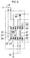
- FIG. 6 shows a fluid control device for use in apparatus for producing semiconductors.
- the device consists of a plurality of lines each comprising a massflow controller 31, two inlet on-off valves 32, 33 provided at the inlet side of the controller 31, and two or three outlet on-off valves 34, 35, 36 arranged at the outlet side of the controller.
- the inlet on-off valves 32, 33 are used for selectively supplying one of two kinds of gases, i.e., process gas A and purge gas B, while the outlet on-off valves 34, 35, 36 are provided for a line leading to a process chamber, a vent line and an evacuating line for a change-over from one line to another.
- Process gas A is a gas of which high purity is required and which is expensive.
- Such a fluid control device has channels for passing the gases A and B, i.e., a main channel 37 in communication with the inlet of a channel within the massflow controller 31, a relatively long subchannel 38 and a relatively short subchannel 39.
- the relatively short subchannel 39 is thought useful for passing process gas A to be assured of high purity in ensuring the purity of process gas A and reducing the amount thereof to be used.
- An object of the present invention is to provide a fluid control device which is optimized in ensuring the purity of the fluid, such as process gas, to be assured of high purity and in reducing the amount thereof to be used, by introducing the concept of a minimized dead volume (stagnant portion of fluid) in connection with the fluid of which high purity is required.
- the present invention provides a fluid control device wherein a valve main body has formed therein a main channel communicating with an inlet or outlet of a channel within a controller for regulating the pressure or flow rate of fluids, and a relatively long subchannel and a relatively short subchannel both communicating with the main channel, one of the subchannels being serviceable for a fluid to be assured of high purity, the fluid control device being characterized in that the subchannel for passing therethrough the fluid to be assured of high purity is the relatively long subchannel.
- a "relatively long subchannel" refers to the longer subchannel when the valve main body has two subchannels, or to the longest subchannel when the valve main body has three subchannels. When there are three subchannels, it is desired that the longer of the two remaining subchannels be used for a fluid which is the second in the order of importance of ensuring purity.
- the fluid to be assured of high purity is the process gas, and the fluid which is the second in the order of importance of ensuring purity is the purge gas.
- the dead volume involved in passing the fluid to be assured of high purity is smaller in the fluid control device of the invention than in the conventional devices. This diminishes the reduction of purity occurring in starting to pass the fluid of which high purity is required. Accordingly the present device produces optimized effects in ensuring the purity of the fluid to be assured of high purity and in reducing the amount of the fluid to be used.
- FIG. 1 shows an embodiment of fluid control device of the present invention.
- Two on-off valves 2, 3 are provided at the inlet side of a massflow controller 1 and positioned one above the other as opposed to each other.
- the upper on-off valve 2 and the lower on-off valve 3 have their main bodies 4, 5 joined to each other.
- An actuator 6 for the upper on-off valve 2 is mounted on the top of the valve main body 4, while an actuator 7 for the lower on-off valve 3 is attached to the bottom of the valve main body 5.
- the main body 5 of the lower on-off valve 3 is joined to a channel block 8 provided at the inlet side of the massflow controller 1.
- the upper and lower valve main bodies 4, 5 are provided with inlet pipe joints 9, 10, respectively.
- the upper valve main body 4 is formed with an L-shaped inflow channel 11 and an I-shaped outflow channel 12.
- the outflow channel 12 is downwardly opened.
- the lower valve main body 5 is formed with an inverted L-shaped inflow channel 13 symmetric with the L-shaped inflow channel 11 of the upper valve main body 4, a reverse L-shaped outflow channel 14 generally symmetric with the inflow channel 13, and a bypass channel 15 holding the outflow channel 14 in communication with the outflow channel 12 of the upper valve main body 4.
- the reverse L-shaped outflow channel 14 of the lower valve main body 5 comprises a main channel 16 communicating with the controller 1 for regulating the pressure or flow rate of a fluid, and a subchannel 17 communicating with the main channel 16 and connected to the inflow channel 13 by the lower valve actuator 7.
- the main channel 16 is used not only as an outflow channel for the fluid to be admitted through the lower inlet pipe joint 10 but also as the outflow channel for the fluid to be admitted via the upper inlet pipe joint 9.
- the fluid control device has a relatively long subchannel 18 comprising the outflow channel 12 of the upper valve main body 4 and the bypass channel 15 of the lower valve main body 5, and the subchannel 17 which is relatively short and which provides part of the outflow channel 14.
- Process gas A is passed through the relatively long subchannel 18, and purge gas B through the relatively short subchannel 17.
- FIG. 2 shows a fluid control device which comprises the same components as in FIG. 1 and which differs from the device of FIG. 1 only in that purge gas B is passed through a relatively long subchannel 18, with process gas A passed through a relatively short subchannel 17.
- the dead volume involved in passing fluid A to be assured of high purity is only the portion of the relative short subchannel 17 indicated by dotting in FIG. 1.
- the dead volume involved in passing the fluid to be assured of high purity is the portion of the relatively long subchannel 18 indicated by dotting in FIG. 2.
- FIG. 3 shows variations in the purity of process gas after the start of passage of the gas through the fluid control device of the invention shown in FIG. 1. More specifically, the purity of the process gas was determined by checking N 2 , serving as a purge gas, for the reduction of concentration. The gas flow rate for testing was 20 c.c./min. With reference to the drawing, the concentration of N 2 decreased to 5 ppb, i.e., to a background level, during a replacement time of 90 seconds. This indicates that 90 seconds after the start of replacement, the purity of process gas reached a high level for use in the fabrication of semiconductors.
- N 2 serving as a purge gas
- FIG. 4 shows variations in the purity of process gas after the start of passage of the gas through the conventional fluid control device shown in FIG. 2.
- the replacement time was more than 1650 seconds, and the reduced concentration of N 2 still remained as high as 1 ppm even after the lapse of about 30 minutes. This indicates that the process gas of low purity must be used in the meantime or needs to be discarded.
- the dead volume was 0.05 c.c. in the device of FIG. 1 and 0.67 c.c. in the device of FIG. 2.
- Two on-off valves are provided at the outlet side of the massflow controller 1 for a change-over from a line leading to a process chamber to a vent line and vice versa . Based on the same concept as above, a relatively long subchannel is used for the line leading to the process chamber.
- valve main bodies 4, 5 and actuators 6, 7 described are merely an example; such components are usable in a suitably altered combination.
- the two valve main bodies 4, 5 may be combined into an integral body or arranged side by side instead of being positioned one above the other.
- the valve main bodies, as well as the valve actuators, may be three in number. FIG. 5 shows such an example.
- a massflow controller 1 is provided at the outlet side thereof with a valve device 21 comprising a valve main body 22 and three valve actuators 23, 24, 25.
- the valve main body 22 has formed therein a straight channel 26 extending straight from a channel in a channel block 8 disposed at the outlet side of the massflow controller 1.
- the straight channel 26 includes a portion extending from its end adjacent to the block 8 to the actuator 25 most proximate to the massflow controller 1 and serving as a main channel 26a.
- the shortest subchannel 27 is a portion extending from the main channel 26a to the actuator 25 most proximate to the controller 1.
- the subchannel 28, 26b of an intermediate length comprises a portion 26b included in the straight channel 26 and extending between the middle actuator 24 and the actuator 25 most proximate to the controller 1, and a portion 28 extending from the straight channel 26 to the middle actuator 24.
- the longest subchannel 29, 26c, 26b comprises a portion 26c, 26b included in the straight channel 26 and extending between the actuator 23 remotest from the controller 1 and the actuator 25 most proximate to the controller 1, and a channel 29 extending from the straight channel 26 to the actuator 23 remotest from the controller 1.
- the longest subchannel 29, 26c, 26b serves as a line leading to a process gas chamber, the subchannel 28, 26b of intermediate length as a vent line, and the shortest subchannel 27 as an evacuating line.
- the dead volume of the line leading to the process gas chamber is the combination of the shortest subchannel 27 interconnecting the main channel 26a and the actuator 25 most proximate to the controller 1 and the portion 28 interconnecting the straight channel 26 and the middle actuator 24.
- the dead volume of the vent line is the combination of the shortest subchannel 27 interconnecting the main channel 26a and the actuator 25 most proximate to the controller 1, portion 26c included in the straight channel 26 and extending between the actuator 23 remotest from the controller 1 and the middle actuator 24 and the channel 29 interconnecting the straight channel 26 and the actuator 23 remotest from the controller 1.
- the dead volume of the evacuating line is the combination of the longest subchannel 29, 26c, 26b and the portion 28 interconnecting the straight channel 26 and the middle actuator 24.
- the process gas chamber line provided by the longest subchannel 29, 26c, 26b with the smallest dead volume achieves optimized results in ensuring the purity of the process gas and reducing the amount of the gas to be used on the same principle as previously stated. Since the evacuating line is used for removing air to a vacuum, no problem whatever will arise even if the dead volume of the evacuating line is great. It is desired that the subchannel 28, 26b of intermediate length provide the vent line so as to reduce the dead volume of this line.
- the fluid control device comprises a valve main body having formed therein a main channel in communication with an inlet or outlet of a channel within a controller for regulating the pressure or flow rate of fluids, and a relatively long subchannel and a relatively short subchannel both communicating with the main channel, one of the subchannels being serviceable for the fluid to be assured of high purity.
- the relatively long subchannel is used for passing this fluid, the device achieves optimized results in ensuring the high purity of the fluid and in reducing the count of the fluid to be used.
- the longest subchannel is used for the fluid which is the first in the order of importance of ensuring high purity, and the longer of the remaining two subchannels is used for another fluid which is the second in the order of importance.
Landscapes
- Engineering & Computer Science (AREA)
- General Engineering & Computer Science (AREA)
- Mechanical Engineering (AREA)
- Valve Housings (AREA)
- Pipeline Systems (AREA)
- Fluid-Pressure Circuits (AREA)
- Lift Valve (AREA)
- Flow Control (AREA)
Abstract
Description
- The present invention relates to fluid control devices, for example, for use in apparatus for producing semiconductors.
- For example, FIG. 6 shows a fluid control device for use in apparatus for producing semiconductors. The device consists of a plurality of lines each comprising a
massflow controller 31, two inlet on-offvalves controller 31, and two or three outlet on-offvalves valves valves main channel 37 in communication with the inlet of a channel within themassflow controller 31, a relativelylong subchannel 38 and a relativelyshort subchannel 39. Conventionally, the relativelyshort subchannel 39 is thought useful for passing process gas A to be assured of high purity in ensuring the purity of process gas A and reducing the amount thereof to be used. - Our research has revealed that the use of the relatively short subchannel for passing the process gas which should be held at high purity eventually fails to assure the process gas of its purity and to achieve a reduction in the amount of the gas to be used.
- An object of the present invention is to provide a fluid control device which is optimized in ensuring the purity of the fluid, such as process gas, to be assured of high purity and in reducing the amount thereof to be used, by introducing the concept of a minimized dead volume (stagnant portion of fluid) in connection with the fluid of which high purity is required.
- The present invention provides a fluid control device wherein a valve main body has formed therein a main channel communicating with an inlet or outlet of a channel within a controller for regulating the pressure or flow rate of fluids, and a relatively long subchannel and a relatively short subchannel both communicating with the main channel, one of the subchannels being serviceable for a fluid to be assured of high purity, the fluid control device being characterized in that the subchannel for passing therethrough the fluid to be assured of high purity is the relatively long subchannel.
- The expression that "the subchannel for passing therethrough the fluid to be assured of high purity is the relatively long subchannel," when put in another way, can be expressed as the feature that the dead volume involved in passing the fluid to be assured of high purity is minimized.
- The phrase a "relatively long subchannel" refers to the longer subchannel when the valve main body has two subchannels, or to the longest subchannel when the valve main body has three subchannels. When there are three subchannels, it is desired that the longer of the two remaining subchannels be used for a fluid which is the second in the order of importance of ensuring purity. With fluid control devices for use in producing semiconductors, the fluid to be assured of high purity is the process gas, and the fluid which is the second in the order of importance of ensuring purity is the purge gas.
- The dead volume involved in passing the fluid to be assured of high purity is smaller in the fluid control device of the invention than in the conventional devices. This diminishes the reduction of purity occurring in starting to pass the fluid of which high purity is required. Accordingly the present device produces optimized effects in ensuring the purity of the fluid to be assured of high purity and in reducing the amount of the fluid to be used.
-
- FIG. 1 is a front view showing a first embodiment of fluid control device of the invention;
- FIG. 2 is a front view of a conventional fluid control device;
- FIG. 3 is a graph for showing variations in the purity of process gas in the fluid control device of the invention;
- FIG. 4 is a graph for showing variations in the purity of process gas in the conventional fluid control device;
- FIG. 5 is a front view showing a second embodiment of fluid control device of the invention; and
- FIG. 6 is a diagram showing an application example of fluid control device with which the invention is concerned.
- Embodiments of the invention will be described below with reference to the drawings. The terms "upper" and "lower" as used in the following description are based on the illustration.
- FIG. 1 shows an embodiment of fluid control device of the present invention. Two on-off
valves massflow controller 1 and positioned one above the other as opposed to each other. The upper on-offvalve 2 and the lower on-offvalve 3 have theirmain bodies 4, 5 joined to each other. An actuator 6 for the upper on-offvalve 2 is mounted on the top of the valve main body 4, while anactuator 7 for the lower on-offvalve 3 is attached to the bottom of the valvemain body 5. Themain body 5 of the lower on-offvalve 3 is joined to achannel block 8 provided at the inlet side of themassflow controller 1. The upper and lower valvemain bodies 4, 5 are provided withinlet pipe joints 9, 10, respectively. The upper valve main body 4 is formed with an L-shaped inflow channel 11 and an I-shaped outflow channel 12. Theoutflow channel 12 is downwardly opened. The lower valvemain body 5 is formed with an inverted L-shaped inflow channel 13 symmetric with the L-shaped inflow channel 11 of the upper valve main body 4, a reverse L-shaped outflow channel 14 generally symmetric with theinflow channel 13, and abypass channel 15 holding theoutflow channel 14 in communication with theoutflow channel 12 of the upper valve main body 4. The reverse L-shaped outflow channel 14 of the lower valvemain body 5 comprises amain channel 16 communicating with thecontroller 1 for regulating the pressure or flow rate of a fluid, and asubchannel 17 communicating with themain channel 16 and connected to theinflow channel 13 by thelower valve actuator 7. Themain channel 16 is used not only as an outflow channel for the fluid to be admitted through the lowerinlet pipe joint 10 but also as the outflow channel for the fluid to be admitted via the upper inlet pipe joint 9. - The fluid control device has a relatively
long subchannel 18 comprising theoutflow channel 12 of the upper valve main body 4 and thebypass channel 15 of the lower valvemain body 5, and thesubchannel 17 which is relatively short and which provides part of theoutflow channel 14. Process gas A is passed through the relativelylong subchannel 18, and purge gas B through the relativelyshort subchannel 17. - The reason for using the relatively
long subchannel 18 for passing process gas A will be described with reference to FIGS. 1 to 4. FIG. 2 shows a fluid control device which comprises the same components as in FIG. 1 and which differs from the device of FIG. 1 only in that purge gas B is passed through a relativelylong subchannel 18, with process gas A passed through a relativelyshort subchannel 17. - With the fluid control device shown in FIG. 1, therefore, the dead volume involved in passing fluid A to be assured of high purity is only the portion of the relative
short subchannel 17 indicated by dotting in FIG. 1. Conversely, if the relativelyshort subchannel 17 is used for passing the fluid to be assured of high purity as in the prior art, the dead volume involved in passing the fluid to be assured of high purity is the portion of the relativelylong subchannel 18 indicated by dotting in FIG. 2. These drawings reveal that the device of the invention is much smaller than the prior-art device in dead volume. - FIG. 3 shows variations in the purity of process gas after the start of passage of the gas through the fluid control device of the invention shown in FIG. 1. More specifically, the purity of the process gas was determined by checking N2, serving as a purge gas, for the reduction of concentration. The gas flow rate for testing was 20 c.c./min. With reference to the drawing, the concentration of N2 decreased to 5 ppb, i.e., to a background level, during a replacement time of 90 seconds. This indicates that 90 seconds after the start of replacement, the purity of process gas reached a high level for use in the fabrication of semiconductors.
- On the other hand, FIG. 4 shows variations in the purity of process gas after the start of passage of the gas through the conventional fluid control device shown in FIG. 2. The same method as above was used. With reference to the drawing, the replacement time was more than 1650 seconds, and the reduced concentration of N2 still remained as high as 1 ppm even after the lapse of about 30 minutes. This indicates that the process gas of low purity must be used in the meantime or needs to be discarded.
- In the above experiment, the dead volume was 0.05 c.c. in the device of FIG. 1 and 0.67 c.c. in the device of FIG. 2.
- Two on-off valves are provided at the outlet side of the
massflow controller 1 for a change-over from a line leading to a process chamber to a vent line and vice versa. Based on the same concept as above, a relatively long subchannel is used for the line leading to the process chamber. - The combination of valve
main bodies 4, 5 andactuators 6, 7 described is merely an example; such components are usable in a suitably altered combination. For example, the two valvemain bodies 4, 5 may be combined into an integral body or arranged side by side instead of being positioned one above the other. The valve main bodies, as well as the valve actuators, may be three in number. FIG. 5 shows such an example. - With reference to FIG. 5, a
massflow controller 1 is provided at the outlet side thereof with avalve device 21 comprising a valvemain body 22 and threevalve actuators main body 22 has formed therein a straight channel 26 extending straight from a channel in achannel block 8 disposed at the outlet side of themassflow controller 1. The straight channel 26 includes a portion extending from its end adjacent to theblock 8 to theactuator 25 most proximate to themassflow controller 1 and serving as amain channel 26a. There are three subchannels. Theshortest subchannel 27 is a portion extending from themain channel 26a to theactuator 25 most proximate to thecontroller 1. Thesubchannel 28, 26b of an intermediate length comprises a portion 26b included in the straight channel 26 and extending between themiddle actuator 24 and theactuator 25 most proximate to thecontroller 1, and aportion 28 extending from the straight channel 26 to themiddle actuator 24. Thelongest subchannel portion 26c, 26b included in the straight channel 26 and extending between the actuator 23 remotest from thecontroller 1 and theactuator 25 most proximate to thecontroller 1, and achannel 29 extending from the straight channel 26 to theactuator 23 remotest from thecontroller 1. Thelongest subchannel subchannel 28, 26b of intermediate length as a vent line, and theshortest subchannel 27 as an evacuating line. - Accordingly, the dead volume of the line leading to the process gas chamber is the combination of the
shortest subchannel 27 interconnecting themain channel 26a and theactuator 25 most proximate to thecontroller 1 and theportion 28 interconnecting the straight channel 26 and themiddle actuator 24. The dead volume of the vent line is the combination of theshortest subchannel 27 interconnecting themain channel 26a and theactuator 25 most proximate to thecontroller 1,portion 26c included in the straight channel 26 and extending between the actuator 23 remotest from thecontroller 1 and themiddle actuator 24 and thechannel 29 interconnecting the straight channel 26 and the actuator 23 remotest from thecontroller 1. The dead volume of the evacuating line is the combination of thelongest subchannel portion 28 interconnecting the straight channel 26 and themiddle actuator 24. - The process gas chamber line provided by the
longest subchannel subchannel 28, 26b of intermediate length provide the vent line so as to reduce the dead volume of this line. - Although the foregoing embodiments are described for use with a gas for producing semiconductors, such devices have the same advantage as described above when used for applications other than production of semiconductors or when used for a liquid instead of gas. Briefly stated, the fluid control device comprises a valve main body having formed therein a main channel in communication with an inlet or outlet of a channel within a controller for regulating the pressure or flow rate of fluids, and a relatively long subchannel and a relatively short subchannel both communicating with the main channel, one of the subchannels being serviceable for the fluid to be assured of high purity. When the relatively long subchannel is used for passing this fluid, the device achieves optimized results in ensuring the high purity of the fluid and in reducing the count of the fluid to be used. In the case where the device has three subchannels, the longest subchannel is used for the fluid which is the first in the order of importance of ensuring high purity, and the longer of the remaining two subchannels is used for another fluid which is the second in the order of importance.
Claims (3)
- A fluid control device wherein a valve main body has formed therein a main channel communicating with an inlet or outlet of a channel within a controller for regulating the pressure or flow rate of fluids, and a relatively long subchannel and a relatively short subchannel both communicating with the main channel, one of the subchannels being serviceable for a fluid to be assured of high purity, the fluid control device being characterized in that the subchannel for passing therethrough the fluid to be assured of high purity is the relatively long subchannel.
- A fluid control device as defined in claim 1 which is characterized in that the valve main body has three subchannels, the longest subchannel is used for the fluid to be assured of high purity, and the second longest subchannel is used for another fluid which is the second in the order of importance of ensuring purity.
- A fluid control device as defined in claim 2 which is characterized in that the fluid to be assured of high purity is a process gas for producing semiconductors, and said another fluid is a purge gas.
Priority Applications (1)
| Application Number | Priority Date | Filing Date | Title |
|---|---|---|---|
| EP02018943A EP1276030A3 (en) | 1996-05-10 | 1997-05-07 | Fluid control device |
Applications Claiming Priority (3)
| Application Number | Priority Date | Filing Date | Title |
|---|---|---|---|
| JP116204/96 | 1996-05-10 | ||
| JP11620496 | 1996-05-10 | ||
| JP11620496A JP3726168B2 (en) | 1996-05-10 | 1996-05-10 | Fluid control device |
Related Child Applications (1)
| Application Number | Title | Priority Date | Filing Date |
|---|---|---|---|
| EP02018943A Division EP1276030A3 (en) | 1996-05-10 | 1997-05-07 | Fluid control device |
Publications (3)
| Publication Number | Publication Date |
|---|---|
| EP0806573A2 true EP0806573A2 (en) | 1997-11-12 |
| EP0806573A3 EP0806573A3 (en) | 1999-07-07 |
| EP0806573B1 EP0806573B1 (en) | 2004-02-04 |
Family
ID=14681423
Family Applications (2)
| Application Number | Title | Priority Date | Filing Date |
|---|---|---|---|
| EP97107532A Expired - Lifetime EP0806573B1 (en) | 1996-05-10 | 1997-05-07 | Fluid control device |
| EP02018943A Withdrawn EP1276030A3 (en) | 1996-05-10 | 1997-05-07 | Fluid control device |
Family Applications After (1)
| Application Number | Title | Priority Date | Filing Date |
|---|---|---|---|
| EP02018943A Withdrawn EP1276030A3 (en) | 1996-05-10 | 1997-05-07 | Fluid control device |
Country Status (9)
| Country | Link |
|---|---|
| US (2) | US5975112A (en) |
| EP (2) | EP0806573B1 (en) |
| JP (1) | JP3726168B2 (en) |
| KR (1) | KR970075396A (en) |
| CA (1) | CA2204939A1 (en) |
| DE (1) | DE69727419T2 (en) |
| IL (1) | IL120804A (en) |
| SG (1) | SG50019A1 (en) |
| TW (1) | TW377387B (en) |
Cited By (4)
| Publication number | Priority date | Publication date | Assignee | Title |
|---|---|---|---|---|
| EP0896177A1 (en) * | 1997-08-05 | 1999-02-10 | Tadahiro Ohmi | Fluid control device |
| WO1999035422A1 (en) * | 1998-01-09 | 1999-07-15 | Swagelok Company | Seal for a modular flow devices |
| US6257270B1 (en) | 1996-05-10 | 2001-07-10 | Tadahiro Ohmi | Fluid control device |
| EP1134429A3 (en) * | 2000-03-17 | 2003-10-15 | DALMEC S.p.A. | A support and distribution element for a pneumatic valve |
Families Citing this family (55)
| Publication number | Priority date | Publication date | Assignee | Title |
|---|---|---|---|---|
| JP3737869B2 (en) * | 1997-05-13 | 2006-01-25 | シーケーディ株式会社 | Process gas supply unit |
| US6345642B1 (en) * | 1999-02-19 | 2002-02-12 | Applied Materials, Inc. | Method and apparatus for removing processing liquid from a processing liquid path |
| FR2794844B1 (en) * | 1999-06-08 | 2001-08-03 | Air Liquide | METHOD AND DEVICE FOR GASTING A CORROSIVE GAS DISTRIBUTION LINE |
| US6817381B2 (en) | 1999-08-24 | 2004-11-16 | Tokyo Electron Limited | Gas processing apparatus, gas processing method and integrated valve unit for gas processing apparatus |
| US6729353B2 (en) | 1999-09-01 | 2004-05-04 | Asml Us, Inc. | Modular fluid delivery apparatus |
| FR2819198B1 (en) * | 2001-01-05 | 2003-09-26 | Yves Lecoffre | METHOD AND DEVICE FOR CONSTITUTING A VOLATILE SUBSTANCE BY EVAPORATION |
| US7334605B2 (en) * | 2002-08-27 | 2008-02-26 | Celerity, Inc. | Modular substrate gas panel having manifold connections in a common plane |
| JP4555052B2 (en) * | 2004-11-04 | 2010-09-29 | シーケーディ株式会社 | Gas supply integrated unit |
| JP4742762B2 (en) * | 2005-09-12 | 2011-08-10 | 株式会社フジキン | Fluid control device |
| US7677236B2 (en) | 2006-05-17 | 2010-03-16 | David Deng | Heater configured to operate with a first or second fuel |
| US7434447B2 (en) * | 2006-05-17 | 2008-10-14 | David Deng | Oxygen depletion sensor |
| US7607426B2 (en) | 2006-05-17 | 2009-10-27 | David Deng | Dual fuel heater |
| US20070277803A1 (en) * | 2006-05-17 | 2007-12-06 | David Deng | Heater |
| US8011920B2 (en) | 2006-12-22 | 2011-09-06 | David Deng | Valve assemblies for heating devices |
| US8241034B2 (en) | 2007-03-14 | 2012-08-14 | Continental Appliances Inc. | Fuel selection valve assemblies |
| US8152515B2 (en) | 2007-03-15 | 2012-04-10 | Continental Appliances Inc | Fuel selectable heating devices |
| US8545216B2 (en) | 2006-12-22 | 2013-10-01 | Continental Appliances, Inc. | Valve assemblies for heating devices |
| US7654820B2 (en) | 2006-12-22 | 2010-02-02 | David Deng | Control valves for heaters and fireplace devices |
| US8403661B2 (en) | 2007-03-09 | 2013-03-26 | Coprecitec, S.L. | Dual fuel heater |
| US7766006B1 (en) | 2007-03-09 | 2010-08-03 | Coprecitec, S.L. | Dual fuel vent free gas heater |
| US8057219B1 (en) | 2007-03-09 | 2011-11-15 | Coprecitec, S.L. | Dual fuel vent free gas heater |
| US8118590B1 (en) | 2007-03-09 | 2012-02-21 | Coprecitec, S.L. | Dual fuel vent free gas heater |
| JP5150628B2 (en) * | 2007-05-31 | 2013-02-20 | 東京エレクトロン株式会社 | Fluid control device |
| US20080302426A1 (en) * | 2007-06-06 | 2008-12-11 | Greg Patrick Mulligan | System and method of securing removable components for distribution of fluids |
| US8122903B2 (en) | 2007-07-26 | 2012-02-28 | Parker-Hannifin Corporation | Close-coupled purgeable vaporizer valve |
| US8307854B1 (en) | 2009-05-14 | 2012-11-13 | Vistadeltek, Inc. | Fluid delivery substrates for building removable standard fluid delivery sticks |
| WO2010144541A2 (en) * | 2009-06-10 | 2010-12-16 | Vistadeltek, Llc | Extreme flow rate and/or high temperature fluid delivery substrates |
| US8465277B2 (en) | 2009-06-29 | 2013-06-18 | David Deng | Heat engine with nozzle |
| US8506290B2 (en) * | 2009-06-29 | 2013-08-13 | David Deng | Heating apparatus with air shutter adjustment |
| US9829195B2 (en) | 2009-12-14 | 2017-11-28 | David Deng | Dual fuel heating source with nozzle |
| US10073071B2 (en) | 2010-06-07 | 2018-09-11 | David Deng | Heating system |
| US8752541B2 (en) | 2010-06-07 | 2014-06-17 | David Deng | Heating system |
| CN202328495U (en) | 2011-11-16 | 2012-07-11 | 普鲁卡姆电器(上海)有限公司 | Multi-air-source balanced gas-fired heater with 360-degree ventilation door adjusting device |
| US8899971B2 (en) | 2010-08-20 | 2014-12-02 | Coprecitec, S.L. | Dual fuel gas heater |
| EP2665972A2 (en) | 2011-01-18 | 2013-11-27 | David Deng | Heating system with pressure regulator |
| US10222057B2 (en) | 2011-04-08 | 2019-03-05 | David Deng | Dual fuel heater with selector valve |
| US9200802B2 (en) * | 2011-04-08 | 2015-12-01 | David Deng | Dual fuel heater with selector valve |
| US9523497B2 (en) | 2012-07-04 | 2016-12-20 | David Deng | Dual fuel heater with selector valve |
| US8985094B2 (en) | 2011-04-08 | 2015-03-24 | David Deng | Heating system |
| US9739389B2 (en) | 2011-04-08 | 2017-08-22 | David Deng | Heating system |
| US8950433B2 (en) | 2011-05-02 | 2015-02-10 | Advantage Group International Inc. | Manifold system for gas and fluid delivery |
| WO2013046660A1 (en) * | 2011-09-30 | 2013-04-04 | 株式会社フジキン | Gas supply device |
| CN102506198B (en) | 2011-10-20 | 2013-05-22 | 南京普鲁卡姆电器有限公司 | Dual-gas-source gas self-adaptive main control valve |
| US9170016B2 (en) | 2012-08-22 | 2015-10-27 | David Deng | Dual fuel heater with selector valve |
| US9175848B2 (en) * | 2011-12-05 | 2015-11-03 | David Deng | Dual fuel heater with selector valve |
| US9022064B2 (en) | 2012-05-10 | 2015-05-05 | David Deng | Dual fuel control device with auxiliary backline pressure regulator |
| US9091431B2 (en) | 2012-09-13 | 2015-07-28 | David Deng | Dual fuel valve with air shutter adjustment |
| US9752779B2 (en) | 2013-03-02 | 2017-09-05 | David Deng | Heating assembly |
| US9423123B2 (en) | 2013-03-02 | 2016-08-23 | David Deng | Safety pressure switch |
| US9454158B2 (en) | 2013-03-15 | 2016-09-27 | Bhushan Somani | Real time diagnostics for flow controller systems and methods |
| US10240789B2 (en) | 2014-05-16 | 2019-03-26 | David Deng | Dual fuel heating assembly with reset switch |
| US10429074B2 (en) | 2014-05-16 | 2019-10-01 | David Deng | Dual fuel heating assembly with selector switch |
| US10550947B2 (en) * | 2015-01-16 | 2020-02-04 | Kitz Sct Corporation | Block valve and block valve for raw material container |
| TW201634738A (en) * | 2015-01-22 | 2016-10-01 | 應用材料股份有限公司 | Improved injector for spatially separated atomic layer deposition chamber |
| US10983537B2 (en) | 2017-02-27 | 2021-04-20 | Flow Devices And Systems Inc. | Systems and methods for flow sensor back pressure adjustment for mass flow controller |
Family Cites Families (24)
| Publication number | Priority date | Publication date | Assignee | Title |
|---|---|---|---|---|
| US462966A (en) | 1891-11-10 | Automatic governor for air-brakes | ||
| US1525393A (en) | 1922-09-19 | 1925-02-03 | John A Jernatowski | Faucet |
| US3797524A (en) * | 1972-06-15 | 1974-03-19 | Reedmer Plastics Inc | Fluid metering device |
| DE2648751C2 (en) | 1976-10-27 | 1986-04-30 | Max-Planck-Gesellschaft zur Förderung der Wissenschaften e.V., 3400 Göttingen | Device for feeding liquid or gaseous substances to a processing vessel |
| US4281683A (en) * | 1978-12-11 | 1981-08-04 | Poly-Glas Systems | Modular multiple-fluid component selection and delivery system |
| US4558845A (en) * | 1982-09-22 | 1985-12-17 | Hunkapiller Michael W | Zero dead volume valve |
| DE3622527C1 (en) * | 1986-07-04 | 1987-05-07 | Draegerwerk Ag | Valve for gas containers |
| JPS6362976A (en) | 1986-08-29 | 1988-03-19 | Daiwa Handotai Sochi Kk | One-way scavenge type valve device for processing semiconductor |
| US4741354A (en) * | 1987-04-06 | 1988-05-03 | Spire Corporation | Radial gas manifold |
| US4738693A (en) * | 1987-04-27 | 1988-04-19 | Advanced Technology Materials, Inc. | Valve block and container for semiconductor source reagent dispensing and/or purification |
| FR2628501B1 (en) * | 1988-03-09 | 1990-05-18 | Eferel Sa | METHOD FOR THE PRODUCTION OF A SHUTTERING DEVICE WITH MULTIPLE SHUTTERS AND INTEGRATED INTERCONNECTION CIRCUITS ACCORDING TO THE FUNCTIONALITIES DESIRED BY THE USER AND SHUTTERING DEVICES REALIZED ACCORDING TO SAID PROCESS. |
| DE3811041A1 (en) | 1988-03-31 | 1989-10-19 | Merck Patent Gmbh | REMOVAL VALVE HEAD FOR CONTAINERS |
| JPH03168494A (en) * | 1989-11-14 | 1991-07-22 | Cryolab Inc | Tee-pipe |
| US5137047A (en) * | 1990-08-24 | 1992-08-11 | Mark George | Delivery of reactive gas from gas pad to process tool |
| US5476118A (en) * | 1991-02-22 | 1995-12-19 | Asahi Yukizai Kogyo Co., Ltd. | Non-stagnant piping system |
| US5224513A (en) * | 1991-06-04 | 1993-07-06 | Cselt - Centro Studi E Laboratori Telecomunicazioni S.P.A. | Device for introducing reagents into an organometallic vapor phase deposition apparatus |
| US5183072A (en) | 1991-10-21 | 1993-02-02 | Matheson Gas Products, Inc. | Automatic switchover valve |
| US5368062A (en) * | 1992-01-29 | 1994-11-29 | Kabushiki Kaisha Toshiba | Gas supplying system and gas supplying apparatus |
| EP0619450A1 (en) | 1993-04-09 | 1994-10-12 | The Boc Group, Inc. | Zero Dead-Leg Gas Cabinet |
| JP3387630B2 (en) | 1994-06-16 | 2003-03-17 | 株式会社フジキン | Block valve |
| JP3546275B2 (en) | 1995-06-30 | 2004-07-21 | 忠弘 大見 | Fluid control device |
| JP3726168B2 (en) | 1996-05-10 | 2005-12-14 | 忠弘 大見 | Fluid control device |
| JP3650859B2 (en) | 1996-06-25 | 2005-05-25 | 忠弘 大見 | Circuit breaker and fluid control apparatus having the same |
| WO1998002684A1 (en) | 1996-07-16 | 1998-01-22 | Controls Corporation Of America | Gas flow control device for high purity, highly corrosive gas service |
-
1996
- 1996-05-10 JP JP11620496A patent/JP3726168B2/en not_active Expired - Fee Related
-
1997
- 1997-05-07 KR KR1019970017375A patent/KR970075396A/en not_active Abandoned
- 1997-05-07 EP EP97107532A patent/EP0806573B1/en not_active Expired - Lifetime
- 1997-05-07 EP EP02018943A patent/EP1276030A3/en not_active Withdrawn
- 1997-05-07 TW TW086106068A patent/TW377387B/en active
- 1997-05-07 DE DE69727419T patent/DE69727419T2/en not_active Expired - Fee Related
- 1997-05-08 IL IL12080497A patent/IL120804A/en not_active IP Right Cessation
- 1997-05-08 US US08/853,347 patent/US5975112A/en not_active Expired - Fee Related
- 1997-05-08 SG SG1997001419A patent/SG50019A1/en unknown
- 1997-05-09 CA CA002204939A patent/CA2204939A1/en not_active Abandoned
-
1999
- 1999-09-03 US US09/389,475 patent/US6257270B1/en not_active Expired - Fee Related
Cited By (7)
| Publication number | Priority date | Publication date | Assignee | Title |
|---|---|---|---|---|
| US6257270B1 (en) | 1996-05-10 | 2001-07-10 | Tadahiro Ohmi | Fluid control device |
| EP0896177A1 (en) * | 1997-08-05 | 1999-02-10 | Tadahiro Ohmi | Fluid control device |
| SG88740A1 (en) * | 1997-08-05 | 2002-05-21 | Fujikin Kk | Fluid control device |
| US6408879B1 (en) | 1997-08-05 | 2002-06-25 | Tadahiro Ohmi | Fluid control device |
| WO1999035422A1 (en) * | 1998-01-09 | 1999-07-15 | Swagelok Company | Seal for a modular flow devices |
| US6123340A (en) * | 1998-01-09 | 2000-09-26 | Swagelok Company | Modular flow devices |
| EP1134429A3 (en) * | 2000-03-17 | 2003-10-15 | DALMEC S.p.A. | A support and distribution element for a pneumatic valve |
Also Published As
| Publication number | Publication date |
|---|---|
| JP3726168B2 (en) | 2005-12-14 |
| EP1276030A2 (en) | 2003-01-15 |
| EP0806573A3 (en) | 1999-07-07 |
| DE69727419D1 (en) | 2004-03-11 |
| SG50019A1 (en) | 1998-06-15 |
| CA2204939A1 (en) | 1997-11-10 |
| KR970075396A (en) | 1997-12-10 |
| JPH09303308A (en) | 1997-11-25 |
| EP0806573B1 (en) | 2004-02-04 |
| US5975112A (en) | 1999-11-02 |
| DE69727419T2 (en) | 2004-12-16 |
| IL120804A (en) | 2000-07-26 |
| IL120804A0 (en) | 1997-09-30 |
| US6257270B1 (en) | 2001-07-10 |
| TW377387B (en) | 1999-12-21 |
| EP1276030A3 (en) | 2003-02-05 |
Similar Documents
| Publication | Publication Date | Title |
|---|---|---|
| US5975112A (en) | Fluid control device | |
| US6273139B1 (en) | Fluid control apparatus | |
| US6035893A (en) | Shutoff-opening devices and fluid control apparatus comprising such devices | |
| JPS6427616A (en) | Valve block and vessel dispensing and/or semiconductor source reactant | |
| EP2656868A3 (en) | Breathing assistance apparatus | |
| KR101132118B1 (en) | Chemical liguid supply system | |
| KR102295310B1 (en) | valve device | |
| KR101638454B1 (en) | Exhaust and load port having therof | |
| US8104516B2 (en) | Gas supply unit and gas supply system | |
| KR0147037B1 (en) | Gas delivery panels | |
| US4913192A (en) | Gas flow control apparatus | |
| US4120331A (en) | Low pressure gas regulator | |
| US6634385B2 (en) | Apparatus for conveying fluids and base plate | |
| KR20160004752A (en) | Exhaust and load port having therof | |
| JPH0647073B2 (en) | Gas supply piping equipment for process equipment | |
| US5370274A (en) | Apparatus for cleaning a wafer surface | |
| JP2000035148A (en) | Integrated fluid control device | |
| JPH09260332A (en) | Substrate processing system chemical supply device | |
| KR100509446B1 (en) | A chemical solution supply apparatus in use the process of fabricating semiconductor device | |
| JP2000240900A (en) | Valve unit | |
| KR200293094Y1 (en) | Apparatus For Supplying Gas For Manufacturing Semiconductor | |
| US7290572B2 (en) | Method for purging a high purity manifold | |
| JPH0722369A (en) | Chemical mixing device for substrate treating apparatus | |
| JP3364379B2 (en) | Substrate processing equipment | |
| JP2001286836A (en) | Device for treating substrate |
Legal Events
| Date | Code | Title | Description |
|---|---|---|---|
| PUAI | Public reference made under article 153(3) epc to a published international application that has entered the european phase |
Free format text: ORIGINAL CODE: 0009012 |
|
| AK | Designated contracting states |
Kind code of ref document: A2 Designated state(s): CH DE FR GB IT LI NL |
|
| PUAL | Search report despatched |
Free format text: ORIGINAL CODE: 0009013 |
|
| AK | Designated contracting states |
Kind code of ref document: A3 Designated state(s): CH DE FR GB IT LI NL |
|
| 17P | Request for examination filed |
Effective date: 19991020 |
|
| 17Q | First examination report despatched |
Effective date: 20020628 |
|
| GRAP | Despatch of communication of intention to grant a patent |
Free format text: ORIGINAL CODE: EPIDOSNIGR1 |
|
| GRAS | Grant fee paid |
Free format text: ORIGINAL CODE: EPIDOSNIGR3 |
|
| GRAA | (expected) grant |
Free format text: ORIGINAL CODE: 0009210 |
|
| AK | Designated contracting states |
Kind code of ref document: B1 Designated state(s): CH DE FR GB IT LI NL |
|
| REG | Reference to a national code |
Ref country code: GB Ref legal event code: FG4D |
|
| REG | Reference to a national code |
Ref country code: CH Ref legal event code: EP |
|
| REF | Corresponds to: |
Ref document number: 69727419 Country of ref document: DE Date of ref document: 20040311 Kind code of ref document: P |
|
| PGFP | Annual fee paid to national office [announced via postgrant information from national office to epo] |
Ref country code: DE Payment date: 20040401 Year of fee payment: 8 |
|
| PGFP | Annual fee paid to national office [announced via postgrant information from national office to epo] |
Ref country code: GB Payment date: 20040426 Year of fee payment: 8 |
|
| PGFP | Annual fee paid to national office [announced via postgrant information from national office to epo] |
Ref country code: NL Payment date: 20040518 Year of fee payment: 8 |
|
| PGFP | Annual fee paid to national office [announced via postgrant information from national office to epo] |
Ref country code: FR Payment date: 20040519 Year of fee payment: 8 |
|
| PGFP | Annual fee paid to national office [announced via postgrant information from national office to epo] |
Ref country code: CH Payment date: 20040524 Year of fee payment: 8 |
|
| ET | Fr: translation filed | ||
| PLBE | No opposition filed within time limit |
Free format text: ORIGINAL CODE: 0009261 |
|
| STAA | Information on the status of an ep patent application or granted ep patent |
Free format text: STATUS: NO OPPOSITION FILED WITHIN TIME LIMIT |
|
| 26N | No opposition filed |
Effective date: 20041105 |
|
| PG25 | Lapsed in a contracting state [announced via postgrant information from national office to epo] |
Ref country code: IT Free format text: LAPSE BECAUSE OF NON-PAYMENT OF DUE FEES Effective date: 20050507 Ref country code: GB Free format text: LAPSE BECAUSE OF NON-PAYMENT OF DUE FEES Effective date: 20050507 |
|
| PG25 | Lapsed in a contracting state [announced via postgrant information from national office to epo] |
Ref country code: LI Free format text: LAPSE BECAUSE OF NON-PAYMENT OF DUE FEES Effective date: 20050531 Ref country code: CH Free format text: LAPSE BECAUSE OF NON-PAYMENT OF DUE FEES Effective date: 20050531 |
|
| PG25 | Lapsed in a contracting state [announced via postgrant information from national office to epo] |
Ref country code: NL Free format text: LAPSE BECAUSE OF NON-PAYMENT OF DUE FEES Effective date: 20051201 Ref country code: DE Free format text: LAPSE BECAUSE OF NON-PAYMENT OF DUE FEES Effective date: 20051201 |
|
| REG | Reference to a national code |
Ref country code: CH Ref legal event code: PL |
|
| GBPC | Gb: european patent ceased through non-payment of renewal fee |
Effective date: 20050507 |
|
| PG25 | Lapsed in a contracting state [announced via postgrant information from national office to epo] |
Ref country code: FR Free format text: LAPSE BECAUSE OF NON-PAYMENT OF DUE FEES Effective date: 20060131 |
|
| NLV4 | Nl: lapsed or anulled due to non-payment of the annual fee |
Effective date: 20051201 |
|
| REG | Reference to a national code |
Ref country code: FR Ref legal event code: ST Effective date: 20060131 |