EP0806570A1 - Scroll type fluid displacement apparatus - Google Patents
Scroll type fluid displacement apparatus Download PDFInfo
- Publication number
- EP0806570A1 EP0806570A1 EP97107669A EP97107669A EP0806570A1 EP 0806570 A1 EP0806570 A1 EP 0806570A1 EP 97107669 A EP97107669 A EP 97107669A EP 97107669 A EP97107669 A EP 97107669A EP 0806570 A1 EP0806570 A1 EP 0806570A1
- Authority
- EP
- European Patent Office
- Prior art keywords
- scroll
- movable
- bushing
- fixed
- displacement apparatus
- Prior art date
- Legal status (The legal status is an assumption and is not a legal conclusion. Google has not performed a legal analysis and makes no representation as to the accuracy of the status listed.)
- Granted
Links
- 239000012530 fluid Substances 0.000 title claims abstract description 50
- 238000006073 displacement reaction Methods 0.000 title claims abstract description 33
- 230000002401 inhibitory effect Effects 0.000 claims abstract description 17
- 230000007246 mechanism Effects 0.000 claims description 44
- 230000001105 regulatory effect Effects 0.000 claims description 23
- 238000003780 insertion Methods 0.000 claims description 5
- 230000037431 insertion Effects 0.000 claims description 5
- 230000008878 coupling Effects 0.000 description 4
- 238000010168 coupling process Methods 0.000 description 4
- 238000005859 coupling reaction Methods 0.000 description 4
- 238000004519 manufacturing process Methods 0.000 description 4
- 230000006835 compression Effects 0.000 description 2
- 238000007906 compression Methods 0.000 description 2
- 229910000831 Steel Inorganic materials 0.000 description 1
- 230000003247 decreasing effect Effects 0.000 description 1
- 238000005242 forging Methods 0.000 description 1
- 238000007789 sealing Methods 0.000 description 1
- 239000010959 steel Substances 0.000 description 1
Images


Classifications
-
- F—MECHANICAL ENGINEERING; LIGHTING; HEATING; WEAPONS; BLASTING
- F01—MACHINES OR ENGINES IN GENERAL; ENGINE PLANTS IN GENERAL; STEAM ENGINES
- F01C—ROTARY-PISTON OR OSCILLATING-PISTON MACHINES OR ENGINES
- F01C17/00—Arrangements for drive of co-operating members, e.g. for rotary piston and casing
- F01C17/06—Arrangements for drive of co-operating members, e.g. for rotary piston and casing using cranks, universal joints or similar elements
- F01C17/063—Arrangements for drive of co-operating members, e.g. for rotary piston and casing using cranks, universal joints or similar elements with only rolling movement
-
- F—MECHANICAL ENGINEERING; LIGHTING; HEATING; WEAPONS; BLASTING
- F04—POSITIVE - DISPLACEMENT MACHINES FOR LIQUIDS; PUMPS FOR LIQUIDS OR ELASTIC FLUIDS
- F04C—ROTARY-PISTON, OR OSCILLATING-PISTON, POSITIVE-DISPLACEMENT MACHINES FOR LIQUIDS; ROTARY-PISTON, OR OSCILLATING-PISTON, POSITIVE-DISPLACEMENT PUMPS
- F04C29/00—Component parts, details or accessories of pumps or pumping installations, not provided for in groups F04C18/00 - F04C28/00
- F04C29/0021—Systems for the equilibration of forces acting on the pump
-
- F—MECHANICAL ENGINEERING; LIGHTING; HEATING; WEAPONS; BLASTING
- F04—POSITIVE - DISPLACEMENT MACHINES FOR LIQUIDS; PUMPS FOR LIQUIDS OR ELASTIC FLUIDS
- F04C—ROTARY-PISTON, OR OSCILLATING-PISTON, POSITIVE-DISPLACEMENT MACHINES FOR LIQUIDS; ROTARY-PISTON, OR OSCILLATING-PISTON, POSITIVE-DISPLACEMENT PUMPS
- F04C29/00—Component parts, details or accessories of pumps or pumping installations, not provided for in groups F04C18/00 - F04C28/00
- F04C29/0042—Driving elements, brakes, couplings, transmissions specially adapted for pumps
- F04C29/005—Means for transmitting movement from the prime mover to driven parts of the pump, e.g. clutches, couplings, transmissions
- F04C29/0057—Means for transmitting movement from the prime mover to driven parts of the pump, e.g. clutches, couplings, transmissions for eccentric movement
-
- F—MECHANICAL ENGINEERING; LIGHTING; HEATING; WEAPONS; BLASTING
- F04—POSITIVE - DISPLACEMENT MACHINES FOR LIQUIDS; PUMPS FOR LIQUIDS OR ELASTIC FLUIDS
- F04C—ROTARY-PISTON, OR OSCILLATING-PISTON, POSITIVE-DISPLACEMENT MACHINES FOR LIQUIDS; ROTARY-PISTON, OR OSCILLATING-PISTON, POSITIVE-DISPLACEMENT PUMPS
- F04C2240/00—Components
- F04C2240/80—Other components
- F04C2240/807—Balance weight, counterweight
-
- Y—GENERAL TAGGING OF NEW TECHNOLOGICAL DEVELOPMENTS; GENERAL TAGGING OF CROSS-SECTIONAL TECHNOLOGIES SPANNING OVER SEVERAL SECTIONS OF THE IPC; TECHNICAL SUBJECTS COVERED BY FORMER USPC CROSS-REFERENCE ART COLLECTIONS [XRACs] AND DIGESTS
- Y10—TECHNICAL SUBJECTS COVERED BY FORMER USPC
- Y10T—TECHNICAL SUBJECTS COVERED BY FORMER US CLASSIFICATION
- Y10T29/00—Metal working
- Y10T29/49—Method of mechanical manufacture
- Y10T29/49229—Prime mover or fluid pump making
- Y10T29/49236—Fluid pump or compressor making
- Y10T29/4924—Scroll or peristaltic type
Definitions
- the present invention relates to a scroll type fluid displacement apparatus and, in particular, to a driving mechanism for an orbiting or movable scroll in the scroll type fluid displacement apparatus.
- U. S. Pat. No. 4,597,724 discloses a conventional scroll type fluid displacement apparatus including a fixed scroll, a movable scroll coupled to the fixed scroll, and a driving mechanism which is for causing a circular orbital motion of the movable scroll in dependence on a rotation of a main shaft.
- the orbital motion causes fluid pockets formed between the fixed scroll and the movable scroll to move and change their volumes to thereby compress introduced fluid.
- a scroll type fluid displacement apparatus may be called a scroll type compressor.
- a rotation inhibiting mechanism is further provided in the fluid displacement apparatus.
- the lower limit of a radius of the orbital motion of the movable scroll can not be regulated.
- a radius of the orbital motion of the movable scroll becomes so small upon start-up of the fluid displacement apparatus that the fluid displacement apparatus does not start the displacing operation.
- the Oldham's coupling mechanism as such a rotation inhibiting mechanism, the upper limit of the orbital motion radius can not be regulated.
- a balance weight largely swings to interfere with the inner periphery of the apparatus housing.
- a swing regulating mechanism is further required in the conventional fluid displacement apparatus for regulating a swing magnitude (orbital motion radius) of the movable scroll.
- the swing regulating mechanism is further utilized for facilitating assembling of the movable scroll.
- a scroll type fluid displacement apparatus to which this invention is applicable comprises a fixed scroll, a movable scroll coupled to the fixed scroll for defining fluid pockets in cooperation with the fixed scroll therebetween, a main shaft to be rotated around a predetermined axis, a driving mechanism connected to the movable scroll and the main shaft for making the movable scroll have an orbital motion around the predetermined axis relative to the fixed scroll in dependence on rotation of the main shaft to displace the fluid pockets, and a rotation inhibiting mechanism connected between the fixed and the movable scrolls for inhibiting rotation of the movable scroll around the predetermined axis.
- the driving mechanism comprises a large-diameter portion integral with the main shaft, a bushing facing the large-diameter portion and rotatably held to the movable scroll, a balance weight interposed between the large-diameter portion and the bushing and attached to the bushing, and a drive pin connected to an eccentric portion of the large-diameter portion and to and an eccentric portion of the bushing for transmitting the rotation of the main shaft to the bushing to cause the orbital motion of the movable scroll.
- the balance weight has a projection which is engaged with the large-diameter portion in a rotation direction of said bushing.
- a main shaft 13 is formed with a main shaft large-diameter portion 15.
- a drive pin 151 is fixed to an end surface of the large-diameter portion 15 at a position offset from the center thereof and projects in an axial direction of the main shaft 13 but away from the main shaft 13. Further, at the center of the large-diameter portion 15 is bored a swing regulating hole 152.
- the movable scroll (not shown) includes an end plate and a spiral element fixed to the end plate at one side thereof. At the other side of the end plate, an annular boss (not shown) is further provided. A thick disc-shaped bushing 33 is received in the boss and rotatably supported via a needle bearing (not shown). A semidisc-shaped balance weight 331 is attached to the bushing 33 so as to extend in a radial direction of the bushing 33.
- the bushing 33 is formed with an eccentric hole 332 at a position offset from the center and further formed with a swing regulating projection 333 at a position offset from the center.
- the bushing 33 is further formed with a pair of rivet holes 334.
- an insertion hole 331a is formed at the virtual center of the semidisc-shaped balance weight 331 assuming it is disc-shaped, and a pair of rivet holes 331b are further formed at positions offset from the insertion hole 331a.
- the balance weight 331 is fixed to the bushing 33 through rivet connection, that is, by inserting a rivet into one pair of the rivet holes 334, 331b and another rivet into the other pair of the rivet holes 334, 331b.
- the swing regulating projection 333 passes through the insertion hole 331a and is further inserted into the swing regulating hole 152.
- the drive pin 151 is rotatably received in the eccentric hole 332.
- a combination of the swing regulating projection 333 and the swing regulating hole 152 will be referred to as a swing regulating mechanism for regulating a swing magnitude (orbital motion radius) of the movable scroll.
- the bushing 33 should be formed through forging and further a special cutting work, such as an eccentric processing, is necessary. This increases the manufacturing cost of the bushing.
- FIG. 2-7 the description will be made as regards a scroll type fluid displacement apparatus according to an embodiment of the present invention. Similar parts will be designated by like reference numerals.
- Fig. 2 will represent the front side of the fluid displacement apparatus while the right side thereof will represent the rear side of the compressor, which is only for the sake of convenience of description and is not intended to limit the invention in any way.
- the fluid displacement apparatus is for compressing fluid and therefore will be called hereinafter a scroll type compressor.
- the compressor includes a compressor housing 10.
- the compressor housing 10 includes a funnel-shaped front end plate (front housing) 11 and a cup-shaped casing 12.
- the main shaft (crankshaft) 13 passes through the front end plate 11 and is formed with the main shaft large-diameter portion 15 at its axially inner end.
- the large-diameter portion 15 is rotatably supported by the front end plate 11 via a ball bearing 16 interposed therebetween.
- the front end plate 11 has a sleeve 17 extending forward and encircling the main shaft 13.
- a ball bearing 19 is disposed at a front end of the sleeve 17 so as to rotatably support the main shaft 13.
- a shaft seal unit 20 is disposed on the main shaft 13 for sealing thereof. The rotation of an external driving source, such as an automobile engine, is transmitted to the main shaft 13 via an electromagnetic clutch 13a.
- a fixed scroll 25 Within the cup-shaped casing 12 are disposed a fixed scroll 25, a movable scroll 26, a rotation inhibiting mechanism 27 and a driving mechanism 28.
- the fixed scroll 25 includes a circular end plate 251 and a spiral element 252 fixed to the end plate 251 at one side thereof.
- the end plate 251 is fixed to the cup-shaped casing 12.
- the movable scroll 26 includes a circular end plate 261 and a spiral element 262 fixed to the end plate 261 at one side thereof.
- the spiral element 262 is interfitted or mated with the spiral element 252 with a phase deviation of 180 degrees so as to define fluid pockets therebetween.
- the movable scroll 26 is coupled to the rotation inhibiting mechanism 27 so as to be prevented from rotation on its axis.
- the movable scroll 26 makes an orbital motion on a given circular orbit depending on the rotation of the main shaft 13 through the driving mechanism 28.
- the orbital motion of the movable scroll 26 compresses the introduced fluid as in the known manner. Specifically, the fluid sucked through a suction port (not shown) is introduced into the fluid pockets which move toward the center while changing their volumes depending on the orbital motion of the movable scroll 26 so as to compress the fluid.
- the compressed fluid is then discharged into a discharge chamber 29 through a discharge hole (not shown) bored through the end plate 251.
- the description will be directed to the driving mechanism 28.
- the drive pin 151 is fixed to an end surface of the main shaft large-diameter portion 15 at a position offset from the center thereof and projects in an axial direction of the main shaft 13 but away from the main shaft 13. Further, at the center of the large-diameter portion 15 is bored a positioning hole 153 corresponding to the swing regulating hole (152 in Fig. 1).
- An annular boss 263 is provided on the end plate 261 of the movable scroll 26 on a side thereof opposite to the side where the spiral element 262 is provided.
- the thick disc-shaped bushing 33 is received in the boss 263 and rotatably supported via a needle bearing 34.
- the semidisc-shaped balance weight 331 is attached to the bushing 33 so as to extend in a radial direction of the bushing 33.
- the bushing 33 is formed with the eccentric hole 332 at a position offset from the center and further formed with the rivet holes 334.
- a positioning projection 331c is formed at the virtual center of the semidisc-shaped balance weight 331 assuming it is disc-shaped, and the rivet holes 331b are further formed at positions offset from the positioning projection 331c.
- the positioning projection 331c has a diameter slightly smaller than that of the positioning hole 153 and is formed by half-blanking a corresponding portion of the balance weight 331 through a press work.
- the balance weight 331 is fixed to the bushing 33 through rivet connection, that is, by inserting a rivet into one pair of the rivet holes 334, 331b and another rivet into the other pair of the rivet holes 334, 331b. Then, the positioning projection 331c is inserted into the positioning hole 153. On the other hand, the drive pin 151 is received in the eccentric hole 332 and rotatably supported by a needle bearing (not shown).
- the rotation inhibiting mechanism 27 includes a pair of annular races 27a and 27b and a plurality of balls 27c arranged between the annular races 27a and 27b at regular intervals in a circumferential direction thereof.
- the race 27a is fixed to the end plate 261 of the movable scroll 26, while the race 27b is fixed to the front end plate 11.
- a plurality of annular grooves are formed at regular intervals in the circumferential direction for receiving therein the corresponding balls 27c, respectively.
- Each groove has a cross section of a circular arc having a radius of curvature slightly greater than that of the ball 27 so that each ball 27 rolls along the corresponding pair of grooves of the races 27a and 27b.
- a diameter of a circular orbit along a bottom of each groove is set substantially equal to a radius of the orbital motion of the movable scroll 26.
- the bushing 33 makes an orbital motion due to the movement of the drive pin 151.
- the center of the movable scroll 26 revolves or orbits around an axis of the main shaft 13. Since the rotation of the movable scroll 26 on its axis is inhibited by the rotation inhibiting mechanism 27, the movable scroll 26 only makes the orbital motion. As described before, when the movable scroll 26 makes the orbital motion, the compression of the fluid is achieved.
- the rotation inhibiting mechanism 27 regulates the radius of the orbital motion of the movable scroll 26 in terms of both the upper and lower limits.
- the positioning of the movable scroll 26 relative to the main shaft 13 is performed by the engagement between the positioning hole 153 formed in the main shaft large-diameter portion 15 and the positioning projection 331c formed on the balance weight 331.
- the positioning projection 331c is inserted into the positioning hole 153 on carrying out an operation in which the main shaft 13 is coupled to the movable scroll 26.
- the positioning projection 331c becomes unnecessary. Therefore, the positioning projection 331c may be worn out as a result of an operation of the compressor.
Landscapes
- Engineering & Computer Science (AREA)
- Mechanical Engineering (AREA)
- General Engineering & Computer Science (AREA)
- Rotary Pumps (AREA)
Abstract
Description
- The present invention relates to a scroll type fluid displacement apparatus and, in particular, to a driving mechanism for an orbiting or movable scroll in the scroll type fluid displacement apparatus.
- For example, U. S. Pat. No. 4,597,724 discloses a conventional scroll type fluid displacement apparatus including a fixed scroll, a movable scroll coupled to the fixed scroll, and a driving mechanism which is for causing a circular orbital motion of the movable scroll in dependence on a rotation of a main shaft. The orbital motion causes fluid pockets formed between the fixed scroll and the movable scroll to move and change their volumes to thereby compress introduced fluid. Accordingly, such a scroll type fluid displacement apparatus may be called a scroll type compressor.
- In such a scroll type fluid displacement apparatus, it is necessary to inhibit the rotation of the movable scroll on its axis while performing the orbital motion. For this purpose, a rotation inhibiting mechanism is further provided in the fluid displacement apparatus.
- As appreciated, when using a ball coupling mechanism or an Oldham's coupling mechanism as such a rotation inhibiting mechanism, the lower limit of a radius of the orbital motion of the movable scroll can not be regulated. Thus, for example, it is possible that a radius of the orbital motion of the movable scroll becomes so small upon start-up of the fluid displacement apparatus that the fluid displacement apparatus does not start the displacing operation.
- Furthermore, when using the Oldham's coupling mechanism as such a rotation inhibiting mechanism, the upper limit of the orbital motion radius can not be regulated. Thus, upon mounting the movable scroll via the Oldham's coupling mechanism in an apparatus housing, a balance weight largely swings to interfere with the inner periphery of the apparatus housing.
- Under the circumstances, a swing regulating mechanism is further required in the conventional fluid displacement apparatus for regulating a swing magnitude (orbital motion radius) of the movable scroll. In the conventional fluid displacement apparatus, the swing regulating mechanism is further utilized for facilitating assembling of the movable scroll.
- On the other hand, provision of such a swing regulating mechanism causes the increase in manufacturing cost of the fluid displacement apparatus.
- It is therefore an object of the present invention to provide a scroll type fluid displacement apparatus in which a manufacturing cost can be decreased.
- It is another object of the present invention to provide a scroll type fluid displacement apparatus of the type described, which is easy in assembling and capable of achieving the stable apparatus performance.
- Other objects of this invention will become clear from the description proceeds.
- A scroll type fluid displacement apparatus to which this invention is applicable comprises a fixed scroll, a movable scroll coupled to the fixed scroll for defining fluid pockets in cooperation with the fixed scroll therebetween, a main shaft to be rotated around a predetermined axis, a driving mechanism connected to the movable scroll and the main shaft for making the movable scroll have an orbital motion around the predetermined axis relative to the fixed scroll in dependence on rotation of the main shaft to displace the fluid pockets, and a rotation inhibiting mechanism connected between the fixed and the movable scrolls for inhibiting rotation of the movable scroll around the predetermined axis. In the scroll type fluid displacement apparatus, the driving mechanism comprises a large-diameter portion integral with the main shaft, a bushing facing the large-diameter portion and rotatably held to the movable scroll, a balance weight interposed between the large-diameter portion and the bushing and attached to the bushing, and a drive pin connected to an eccentric portion of the large-diameter portion and to and an eccentric portion of the bushing for transmitting the rotation of the main shaft to the bushing to cause the orbital motion of the movable scroll. In the driving mechanism, the balance weight has a projection which is engaged with the large-diameter portion in a rotation direction of said bushing.
-
- Fig. 1 is an exploded perspective view of a driving mechanism included in a conventional scroll type fluid displacement apparatus;
- Fig. 2 is a longitudinal sectional view of a scroll type fluid displacement apparatus according to an embodiment of the present invention;
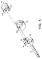
- Fig. 3 is an exploded perspective view of a driving mechanism included in the scroll type fluid displacement apparatus of Fig. 2;
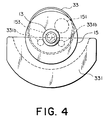
- Fig. 4 is a front view of the driving mechanism;
- Fig. 5 is a front view of a bushing included in the driving mechanism;
- Fig. 6 is a front view of a balance weight included in the driving mechanism; and
- Fig. 7 is a front view of a main shaft included in the driving mechanism.
- For a better understanding of the present invention, description will be made at first as regards a conventional scroll type fluid displacement apparatus which includes a driving mechanism for causing a circular orbital motion of a movable scroll relative to a fixed scroll as discussed in the preamble part.
- Referring to Fig. 1, the driving mechanism will be described. In the driving mechanism, a
main shaft 13 is formed with a main shaft large-diameter portion 15. Adrive pin 151 is fixed to an end surface of the large-diameter portion 15 at a position offset from the center thereof and projects in an axial direction of themain shaft 13 but away from themain shaft 13. Further, at the center of the large-diameter portion 15 is bored aswing regulating hole 152. - The movable scroll (not shown) includes an end plate and a spiral element fixed to the end plate at one side thereof. At the other side of the end plate, an annular boss (not shown) is further provided. A thick disc-
shaped bushing 33 is received in the boss and rotatably supported via a needle bearing (not shown). A semidisc-shaped balance weight 331 is attached to thebushing 33 so as to extend in a radial direction of thebushing 33. - The
bushing 33 is formed with aneccentric hole 332 at a position offset from the center and further formed with aswing regulating projection 333 at a position offset from the center. Thebushing 33 is further formed with a pair ofrivet holes 334. On the other hand, aninsertion hole 331a is formed at the virtual center of the semidisc-shaped balance weight 331 assuming it is disc-shaped, and a pair ofrivet holes 331b are further formed at positions offset from theinsertion hole 331a. - The
balance weight 331 is fixed to thebushing 33 through rivet connection, that is, by inserting a rivet into one pair of therivet holes rivet holes swing regulating projection 333 passes through theinsertion hole 331a and is further inserted into theswing regulating hole 152. On the other hand, thedrive pin 151 is rotatably received in theeccentric hole 332. A combination of theswing regulating projection 333 and theswing regulating hole 152 will be referred to as a swing regulating mechanism for regulating a swing magnitude (orbital motion radius) of the movable scroll. - However, for providing the
swing regulating projection 333, thebushing 33 should be formed through forging and further a special cutting work, such as an eccentric processing, is necessary. This increases the manufacturing cost of the bushing. - On the other hand, if the swing regulating mechanism is not provided, positioning of the movable scroll relative to the main shaft becomes difficult.
- Turning to Figs. 2-7, the description will be made as regards a scroll type fluid displacement apparatus according to an embodiment of the present invention. Similar parts will be designated by like reference numerals.
- In the following description, the left side of Fig. 2 will represent the front side of the fluid displacement apparatus while the right side thereof will represent the rear side of the compressor, which is only for the sake of convenience of description and is not intended to limit the invention in any way. The fluid displacement apparatus is for compressing fluid and therefore will be called hereinafter a scroll type compressor.
- As shown in Fig. 2, the compressor includes a
compressor housing 10. Thecompressor housing 10 includes a funnel-shaped front end plate (front housing) 11 and a cup-shaped casing 12. The main shaft (crankshaft) 13 passes through the front end plate 11 and is formed with the main shaft large-diameter portion 15 at its axially inner end. The large-diameter portion 15 is rotatably supported by the front end plate 11 via a ball bearing 16 interposed therebetween. - The front end plate 11 has a
sleeve 17 extending forward and encircling themain shaft 13. A ball bearing 19 is disposed at a front end of thesleeve 17 so as to rotatably support themain shaft 13. Ashaft seal unit 20 is disposed on themain shaft 13 for sealing thereof. The rotation of an external driving source, such as an automobile engine, is transmitted to themain shaft 13 via anelectromagnetic clutch 13a. - Within the cup-
shaped casing 12 are disposed a fixed scroll 25, amovable scroll 26, a rotation inhibiting mechanism 27 and adriving mechanism 28. - The fixed scroll 25 includes a
circular end plate 251 and aspiral element 252 fixed to theend plate 251 at one side thereof. Theend plate 251 is fixed to the cup-shaped casing 12. Themovable scroll 26 includes acircular end plate 261 and a spiral element 262 fixed to theend plate 261 at one side thereof. - The spiral element 262 is interfitted or mated with the
spiral element 252 with a phase deviation of 180 degrees so as to define fluid pockets therebetween. Themovable scroll 26 is coupled to the rotation inhibiting mechanism 27 so as to be prevented from rotation on its axis. On the other hand, themovable scroll 26 makes an orbital motion on a given circular orbit depending on the rotation of themain shaft 13 through thedriving mechanism 28. The orbital motion of themovable scroll 26 compresses the introduced fluid as in the known manner. Specifically, the fluid sucked through a suction port (not shown) is introduced into the fluid pockets which move toward the center while changing their volumes depending on the orbital motion of themovable scroll 26 so as to compress the fluid. The compressed fluid is then discharged into adischarge chamber 29 through a discharge hole (not shown) bored through theend plate 251. - As shown in Figs. 3-7, the description will be directed to the
driving mechanism 28. In thedriving mechanism 28, thedrive pin 151 is fixed to an end surface of the main shaft large-diameter portion 15 at a position offset from the center thereof and projects in an axial direction of themain shaft 13 but away from themain shaft 13. Further, at the center of the large-diameter portion 15 is bored apositioning hole 153 corresponding to the swing regulating hole (152 in Fig. 1). - An
annular boss 263 is provided on theend plate 261 of themovable scroll 26 on a side thereof opposite to the side where the spiral element 262 is provided. The thick disc-shapedbushing 33 is received in theboss 263 and rotatably supported via aneedle bearing 34. The semidisc-shapedbalance weight 331 is attached to thebushing 33 so as to extend in a radial direction of thebushing 33. - The
bushing 33 is formed with theeccentric hole 332 at a position offset from the center and further formed with the rivet holes 334. On the other hand, apositioning projection 331c is formed at the virtual center of the semidisc-shapedbalance weight 331 assuming it is disc-shaped, and the rivet holes 331b are further formed at positions offset from thepositioning projection 331c. Thepositioning projection 331c has a diameter slightly smaller than that of thepositioning hole 153 and is formed by half-blanking a corresponding portion of thebalance weight 331 through a press work. - The
balance weight 331 is fixed to thebushing 33 through rivet connection, that is, by inserting a rivet into one pair of the rivet holes 334, 331b and another rivet into the other pair of the rivet holes 334, 331b. Then, thepositioning projection 331c is inserted into thepositioning hole 153. On the other hand, thedrive pin 151 is received in theeccentric hole 332 and rotatably supported by a needle bearing (not shown). - Referring back to Fig. 2, the rotation inhibiting mechanism 27 includes a pair of
annular races 27a and 27b and a plurality ofballs 27c arranged between theannular races 27a and 27b at regular intervals in a circumferential direction thereof. Therace 27a is fixed to theend plate 261 of themovable scroll 26, while the race 27b is fixed to the front end plate 11. On each of the confronting surfaces of theraces 27a and 27b, a plurality of annular grooves are formed at regular intervals in the circumferential direction for receiving therein the correspondingballs 27c, respectively. Each groove has a cross section of a circular arc having a radius of curvature slightly greater than that of the ball 27 so that each ball 27 rolls along the corresponding pair of grooves of theraces 27a and 27b. A diameter of a circular orbit along a bottom of each groove is set substantially equal to a radius of the orbital motion of themovable scroll 26. With this arrangement of the rotation inhibiting mechanism 27, the radius of the orbital motion of themovable scroll 26 can be regulated in terms of both the upper and lower limits. - When the
main shaft 13 rotates, thebushing 33 makes an orbital motion due to the movement of thedrive pin 151. As a result, the center of themovable scroll 26 revolves or orbits around an axis of themain shaft 13. Since the rotation of themovable scroll 26 on its axis is inhibited by the rotation inhibiting mechanism 27, themovable scroll 26 only makes the orbital motion. As described before, when themovable scroll 26 makes the orbital motion, the compression of the fluid is achieved. - In the compressor, the rotation inhibiting mechanism 27 regulates the radius of the orbital motion of the
movable scroll 26 in terms of both the upper and lower limits. Thus, the stable compressor performance can be achieved upon start-up of the compressor and during the compression of the fluid without providing the swing regulating projection on thebushing 33 as is required in the prior art. - Further, in the compressor, the positioning of the
movable scroll 26 relative to themain shaft 13 is performed by the engagement between thepositioning hole 153 formed in the main shaft large-diameter portion 15 and thepositioning projection 331c formed on thebalance weight 331. In other words, thepositioning projection 331c is inserted into thepositioning hole 153 on carrying out an operation in which themain shaft 13 is coupled to themovable scroll 26. After themain shaft 13 is coupled to themovable scroll 26, thepositioning projection 331c becomes unnecessary. Therefore, thepositioning projection 331c may be worn out as a result of an operation of the compressor. - With this structure, it is unnecessary to provide a projection on the
bushing 33. This results in enabling thebushing 33 being readily manufactured from a steel rod sold at a market. Thus, the manufacturing cost of the bushing can be reduced, while assembling of themovable scroll 26 is facilitated. - While this invention has thus far been described in conjunction with a single embodiment, it will readily be understood for those skilled in the art to put this invention into practice in various other manners. For example, as the rotation inhibiting mechanism, use may be made of a selected one of similar mechanisms known in the art. Japanese Laid-open (Unexamined) Patent Publication No. 33811/1993 (JP-A-5-33811), the disclosure of which is herein incorporated by reference, discloses a thrust ball bearing which forms the rotation inhibiting mechanism included in the compressor of this specification.
Claims (9)
- A scroll type fluid displacement apparatus comprising:a fixed scroll;a movable scroll coupled to said fixed scroll for defining fluid pockets in cooperation with said fixed scroll therebetween;a main shaft to be rotated around a predetermined axis;a driving mechanism connected to said movable scroll and said main shaft for making said movable scroll have an orbital motion around said predetermined axis relative to said fixed scroll in dependence on rotation of said main shaft to displace said fluid pockets; anda rotation inhibiting mechanism connected between said fixed and said movable scrolls for inhibiting rotation of said movable scroll around said predetermined axis,
said driving mechanism comprising:a large-diameter portion integral with said main shaft;a bushing facing said large-diameter portion and rotatably held to said movable scroll;a balance weight interposed between said large-diameter portion and said bushing and attached to said bushing; anda drive pin connected to an eccentric portion of said large-diameter portion and to and an eccentric portion of said bushing for transmitting said rotation of the main shaft to said bushing to cause said orbital motion of the movable scroll,said balance weight having a projection which is engaged with said large-diameter portion in a rotation direction of said bushing. - A scroll type fluid displacement apparatus as claimed in claim 1, wherein said bushing has an eccentric hole at said eccentric portion thereof, said drive pin being fixed to said large-diameter portion at said eccentric portion thereof and inserted into said eccentric hole.
- A scroll type fluid displacement apparatus as claimed in claim 1, wherein said large-diameter portion has an insertion hole on said predetermined axis, said projection extending parallel to said predetermined axis and being inserted into said insertion hole.
- A scroll type fluid displacement apparatus as claimed in claim 1, wherein said projection is formed by half-blanking a corresponding portion of said balance weight.
- A scroll type fluid displacement apparatus as claimed in claim 1, wherein said projection is for regulating a swing of said bushing relative to said large-diameter portion around said drive pin to determine a radius of the orbital motion of said movable scroll in cooperation with said drive pin.
- A scroll type fluid displacement apparatus as claimed in claim 1, wherein said rotation inhibiting mechanism comprises orbit regulating means connected to said fixed and said movable scrolls for regulating a radius of the orbital motion of said movable scroll, said projection is for positioning said bushing relative to said large-diameter portion in cooperation with said drive pin.
- A scroll type fluid displacement apparatus as claimed in claim 6, wherein said orbit regulating means comprises:a plurality of movable annular grooves connected to said movable scroll, said movable annular grooves arranged at regular intervals in a circumferential direction of said movable scroll;a plurality of fixed annular grooves connected to said fixed scroll, said fixed annular grooves arranged at regular intervals in a circumferential direction of said fixed scroll and facing said movable annular grooves; anda plurality of balls arranged between said movable annular grooves and said fixed annular grooves, each of said balls received in a corresponding pair of said movable annular groove and said fixed annular groove.
- A scroll type fluid displacement apparatus as claimed in claim 7, wherein each of said movable and said fixed annular grooves has a diameter substantially equal to the radius of the orbital motion of said movable scroll.
- A scroll type fluid displacement apparatus as claimed in claim 7, wherein each of said movable and said fixed annular grooves has a cross section of a circular arc having a radius of curvature slightly greater than that of said ball.
Applications Claiming Priority (3)
| Application Number | Priority Date | Filing Date | Title |
|---|---|---|---|
| JP8116533A JPH09303275A (en) | 1996-05-10 | 1996-05-10 | Scroll compressor |
| JP11653396 | 1996-05-10 | ||
| JP116533/96 | 1996-05-10 |
Publications (2)
| Publication Number | Publication Date |
|---|---|
| EP0806570A1 true EP0806570A1 (en) | 1997-11-12 |
| EP0806570B1 EP0806570B1 (en) | 1999-09-08 |
Family
ID=14689488
Family Applications (1)
| Application Number | Title | Priority Date | Filing Date |
|---|---|---|---|
| EP97107669A Expired - Lifetime EP0806570B1 (en) | 1996-05-10 | 1997-05-09 | Scroll type fluid displacement apparatus |
Country Status (7)
| Country | Link |
|---|---|
| US (1) | US5938418A (en) |
| EP (1) | EP0806570B1 (en) |
| JP (1) | JPH09303275A (en) |
| KR (1) | KR970075372A (en) |
| CN (1) | CN1170086A (en) |
| BR (1) | BR9703111A (en) |
| DE (1) | DE69700487T2 (en) |
Cited By (1)
| Publication number | Priority date | Publication date | Assignee | Title |
|---|---|---|---|---|
| EP0924432A1 (en) * | 1997-12-15 | 1999-06-23 | Sanden Corporation | Swing-link mechanism of a scroll-type compressor |
Families Citing this family (8)
| Publication number | Priority date | Publication date | Assignee | Title |
|---|---|---|---|---|
| JP2000055040A (en) | 1998-08-04 | 2000-02-22 | Sanden Corp | Ball coupling |
| JP3249781B2 (en) * | 1998-08-05 | 2002-01-21 | サンデン株式会社 | Thrust ball bearings |
| JP4398539B2 (en) * | 1999-06-01 | 2010-01-13 | サンデン株式会社 | Scroll compressor |
| US6382941B1 (en) | 2000-12-27 | 2002-05-07 | Visteon Global Technologies, Inc. | Device and method to prevent misbuild and improper function of air conditioning scroll compressor due to misplaced or extra steel spherical balls |
| JP5500566B2 (en) * | 2008-04-10 | 2014-05-21 | サンデン株式会社 | Scroll type fluid machinery |
| CN102392820B (en) * | 2011-12-06 | 2015-01-21 | 乔建设 | Adverse-rotation-preventing scroll compressor with fixed eccentric disc |
| DE102016118525B4 (en) * | 2016-09-29 | 2019-09-19 | Hanon Systems | Apparatus for compressing a gaseous fluid |
| CN107269524A (en) * | 2017-07-11 | 2017-10-20 | 上海光裕汽车空调压缩机股份有限公司 | Screw compressor |
Citations (3)
| Publication number | Priority date | Publication date | Assignee | Title |
|---|---|---|---|---|
| US4597724A (en) * | 1983-03-31 | 1986-07-01 | Sanden Corporation | Scroll type fluid displacement apparatus with centrifugal force balanceweight |
| EP0489479A1 (en) * | 1990-12-06 | 1992-06-10 | Mitsubishi Jukogyo Kabushiki Kaisha | Scroll type fluid machinery |
| US5366360A (en) * | 1993-11-12 | 1994-11-22 | General Motors Corporation | Axial positioning limit pin for scroll compressor |
Family Cites Families (9)
| Publication number | Priority date | Publication date | Assignee | Title |
|---|---|---|---|---|
| US4259043A (en) * | 1977-06-17 | 1981-03-31 | Arthur D. Little, Inc. | Thrust bearing/coupling component for orbiting scroll-type machinery and scroll-type machinery incorporating the same |
| US4201521A (en) * | 1978-03-20 | 1980-05-06 | Trw Inc. | Pump and motor assembly |
| JPS56141087A (en) * | 1980-04-05 | 1981-11-04 | Sanden Corp | Scroll type compressor |
| JPS6012956Y2 (en) * | 1980-11-10 | 1985-04-25 | サンデン株式会社 | Scroll compressor |
| JPS57146085A (en) * | 1981-03-03 | 1982-09-09 | Sanden Corp | Scroll type fluid apparatus |
| JPH0781556B2 (en) * | 1987-01-21 | 1995-08-30 | 岩田塗装機工業株式会社 | Thrust bearing mechanism of air-cooled oilless scroll compressor |
| KR920006046B1 (en) * | 1988-04-11 | 1992-07-27 | 가부시기가이샤 히다찌세이사꾸쇼 | Scroll compressor |
| JP2997103B2 (en) * | 1991-07-26 | 2000-01-11 | エヌティエヌ株式会社 | Thrust ball bearings |
| JPH0893665A (en) * | 1994-09-20 | 1996-04-09 | Sanden Corp | Scroll compressor |
-
1996
- 1996-05-10 JP JP8116533A patent/JPH09303275A/en active Pending
-
1997
- 1997-05-08 KR KR1019970017589A patent/KR970075372A/en not_active Application Discontinuation
- 1997-05-09 CN CN97111170A patent/CN1170086A/en active Pending
- 1997-05-09 US US08/853,897 patent/US5938418A/en not_active Expired - Lifetime
- 1997-05-09 EP EP97107669A patent/EP0806570B1/en not_active Expired - Lifetime
- 1997-05-09 DE DE69700487T patent/DE69700487T2/en not_active Expired - Lifetime
- 1997-05-09 BR BR9703111A patent/BR9703111A/en not_active Application Discontinuation
Patent Citations (3)
| Publication number | Priority date | Publication date | Assignee | Title |
|---|---|---|---|---|
| US4597724A (en) * | 1983-03-31 | 1986-07-01 | Sanden Corporation | Scroll type fluid displacement apparatus with centrifugal force balanceweight |
| EP0489479A1 (en) * | 1990-12-06 | 1992-06-10 | Mitsubishi Jukogyo Kabushiki Kaisha | Scroll type fluid machinery |
| US5366360A (en) * | 1993-11-12 | 1994-11-22 | General Motors Corporation | Axial positioning limit pin for scroll compressor |
Cited By (1)
| Publication number | Priority date | Publication date | Assignee | Title |
|---|---|---|---|---|
| EP0924432A1 (en) * | 1997-12-15 | 1999-06-23 | Sanden Corporation | Swing-link mechanism of a scroll-type compressor |
Also Published As
| Publication number | Publication date |
|---|---|
| US5938418A (en) | 1999-08-17 |
| CN1170086A (en) | 1998-01-14 |
| JPH09303275A (en) | 1997-11-25 |
| EP0806570B1 (en) | 1999-09-08 |
| BR9703111A (en) | 1998-09-08 |
| DE69700487D1 (en) | 1999-10-14 |
| KR970075372A (en) | 1997-12-10 |
| DE69700487T2 (en) | 2000-02-17 |
Similar Documents
| Publication | Publication Date | Title |
|---|---|---|
| EP0037728B1 (en) | Improvements in scroll-type fluid compressors | |
| EP0078148B1 (en) | Biased drive mechanism for an orbiting fluid displacement member | |
| EP0061698B1 (en) | Orbiting piston type fluid displacement apparatus with a rotation preventing device | |
| JP2712914B2 (en) | Scroll compressor | |
| US4589828A (en) | Rotation preventing device for an orbiting member of a fluid displacement apparatus | |
| EP0317270B1 (en) | Scroll compressor | |
| EP0090931A2 (en) | Movement synchronizing means for scroll-type fluid displacement apparatus | |
| EP0227249A1 (en) | Axial sealing mechanism for scroll type fluid displacement apparatus | |
| EP0107409A1 (en) | Scroll type compressor with lubricating system | |
| EP0060495B1 (en) | An improved rotation preventing device for an orbiting piston type fluid apparatus | |
| US5779461A (en) | Scroll type fluid displacement apparatus having a control system of line contacts between spiral elements | |
| EP0052461A1 (en) | Scroll-type fluid displacement apparatus with means for counteracting centrifugal forces | |
| US5938418A (en) | Scroll type fluid displacement apparatus with decreased manufacturing cost | |
| EP0039623B1 (en) | Improvements in or relating to scroll-type fluid displacement apparatus | |
| EP0078128B1 (en) | A drive bearing device for a fluid displacement apparatus | |
| CA1220379A (en) | Rotation preventing device for an orbiting piston type fluid displacement apparatus | |
| CA1227173A (en) | Interfitting mechanism of spiral elements for scroll type fluid displacement apparatus | |
| AU658530B2 (en) | Orbiting member fluid displacement apparatus with rotation preventing mechanism | |
| AU1837999A (en) | Scroll-type fluid machine in which a movable scroll member is elastically urged towards a fixed scroll member | |
| EP0122068B1 (en) | Interfitting mechanism of spiral elements for scroll type fluid displacement apparatus | |
| US4575319A (en) | Method and apparatus for adjusting the angular relationship of spiral elements in a scroll type fluid displacement apparatus | |
| JP4051121B2 (en) | Hermetic compressor | |
| JPH0842467A (en) | Scroll compressor | |
| EP0075053A1 (en) | Wear-resisting means for scroll-type fluid-displacement apparatuses | |
| EP0627559B1 (en) | Inspection system for a defective rotation preventing device in an orbiting member of a fluid displacement apparatus |
Legal Events
| Date | Code | Title | Description |
|---|---|---|---|
| PUAI | Public reference made under article 153(3) epc to a published international application that has entered the european phase |
Free format text: ORIGINAL CODE: 0009012 |
|
| AK | Designated contracting states |
Kind code of ref document: A1 Designated state(s): DE FR IT SE |
|
| 17P | Request for examination filed |
Effective date: 19980220 |
|
| 17Q | First examination report despatched |
Effective date: 19980515 |
|
| GRAG | Despatch of communication of intention to grant |
Free format text: ORIGINAL CODE: EPIDOS AGRA |
|
| GRAG | Despatch of communication of intention to grant |
Free format text: ORIGINAL CODE: EPIDOS AGRA |
|
| GRAH | Despatch of communication of intention to grant a patent |
Free format text: ORIGINAL CODE: EPIDOS IGRA |
|
| GRAH | Despatch of communication of intention to grant a patent |
Free format text: ORIGINAL CODE: EPIDOS IGRA |
|
| GRAA | (expected) grant |
Free format text: ORIGINAL CODE: 0009210 |
|
| ITF | It: translation for a ep patent filed | ||
| AK | Designated contracting states |
Kind code of ref document: B1 Designated state(s): DE FR IT SE |
|
| REF | Corresponds to: |
Ref document number: 69700487 Country of ref document: DE Date of ref document: 19991014 |
|
| ET | Fr: translation filed | ||
| PLBE | No opposition filed within time limit |
Free format text: ORIGINAL CODE: 0009261 |
|
| STAA | Information on the status of an ep patent application or granted ep patent |
Free format text: STATUS: NO OPPOSITION FILED WITHIN TIME LIMIT |
|
| 26N | No opposition filed | ||
| PGFP | Annual fee paid to national office [announced via postgrant information from national office to epo] |
Ref country code: SE Payment date: 20130507 Year of fee payment: 17 Ref country code: DE Payment date: 20130531 Year of fee payment: 17 |
|
| PGFP | Annual fee paid to national office [announced via postgrant information from national office to epo] |
Ref country code: FR Payment date: 20130531 Year of fee payment: 17 Ref country code: IT Payment date: 20130520 Year of fee payment: 17 |
|
| REG | Reference to a national code |
Ref country code: DE Ref legal event code: R119 Ref document number: 69700487 Country of ref document: DE |
|
| PG25 | Lapsed in a contracting state [announced via postgrant information from national office to epo] |
Ref country code: SE Free format text: LAPSE BECAUSE OF NON-PAYMENT OF DUE FEES Effective date: 20140510 |
|
| REG | Reference to a national code |
Ref country code: SE Ref legal event code: EUG |
|
| REG | Reference to a national code |
Ref country code: DE Ref legal event code: R119 Ref document number: 69700487 Country of ref document: DE Effective date: 20141202 |
|
| REG | Reference to a national code |
Ref country code: FR Ref legal event code: ST Effective date: 20150130 |
|
| PG25 | Lapsed in a contracting state [announced via postgrant information from national office to epo] |
Ref country code: DE Free format text: LAPSE BECAUSE OF NON-PAYMENT OF DUE FEES Effective date: 20141202 Ref country code: IT Free format text: LAPSE BECAUSE OF NON-PAYMENT OF DUE FEES Effective date: 20140509 |
|
| PG25 | Lapsed in a contracting state [announced via postgrant information from national office to epo] |
Ref country code: FR Free format text: LAPSE BECAUSE OF NON-PAYMENT OF DUE FEES Effective date: 20140602 |