EP0090931A2 - Movement synchronizing means for scroll-type fluid displacement apparatus - Google Patents
Movement synchronizing means for scroll-type fluid displacement apparatus Download PDFInfo
- Publication number
- EP0090931A2 EP0090931A2 EP83101502A EP83101502A EP0090931A2 EP 0090931 A2 EP0090931 A2 EP 0090931A2 EP 83101502 A EP83101502 A EP 83101502A EP 83101502 A EP83101502 A EP 83101502A EP 0090931 A2 EP0090931 A2 EP 0090931A2
- Authority
- EP
- European Patent Office
- Prior art keywords
- scroll member
- orbiting scroll
- pockets
- fixed ring
- keys
- Prior art date
- Legal status (The legal status is an assumption and is not a legal conclusion. Google has not performed a legal analysis and makes no representation as to the accuracy of the status listed.)
- Withdrawn
Links
Images


Classifications
-
- F—MECHANICAL ENGINEERING; LIGHTING; HEATING; WEAPONS; BLASTING
- F01—MACHINES OR ENGINES IN GENERAL; ENGINE PLANTS IN GENERAL; STEAM ENGINES
- F01C—ROTARY-PISTON OR OSCILLATING-PISTON MACHINES OR ENGINES
- F01C21/00—Component parts, details or accessories not provided for in groups F01C1/00 - F01C20/00
- F01C21/003—Systems for the equilibration of forces acting on the elements of the machine
-
- F—MECHANICAL ENGINEERING; LIGHTING; HEATING; WEAPONS; BLASTING
- F01—MACHINES OR ENGINES IN GENERAL; ENGINE PLANTS IN GENERAL; STEAM ENGINES
- F01C—ROTARY-PISTON OR OSCILLATING-PISTON MACHINES OR ENGINES
- F01C1/00—Rotary-piston machines or engines
- F01C1/02—Rotary-piston machines or engines of arcuate-engagement type, i.e. with circular translatory movement of co-operating members, each member having the same number of teeth or tooth-equivalents
- F01C1/0207—Rotary-piston machines or engines of arcuate-engagement type, i.e. with circular translatory movement of co-operating members, each member having the same number of teeth or tooth-equivalents both members having co-operating elements in spiral form
- F01C1/0215—Rotary-piston machines or engines of arcuate-engagement type, i.e. with circular translatory movement of co-operating members, each member having the same number of teeth or tooth-equivalents both members having co-operating elements in spiral form where only one member is moving
-
- F—MECHANICAL ENGINEERING; LIGHTING; HEATING; WEAPONS; BLASTING
- F01—MACHINES OR ENGINES IN GENERAL; ENGINE PLANTS IN GENERAL; STEAM ENGINES
- F01C—ROTARY-PISTON OR OSCILLATING-PISTON MACHINES OR ENGINES
- F01C17/00—Arrangements for drive of co-operating members, e.g. for rotary piston and casing
- F01C17/06—Arrangements for drive of co-operating members, e.g. for rotary piston and casing using cranks, universal joints or similar elements
- F01C17/066—Arrangements for drive of co-operating members, e.g. for rotary piston and casing using cranks, universal joints or similar elements with an intermediate piece sliding along perpendicular axes, e.g. Oldham coupling
Definitions
- This invention relates to scroll-type fluid displacement apparatus.
- U.S. Patent No. 801,182 discloses a device including two scroll members each having an end plate and a spiroidal or involute spiral element.
- the scroll members are maintained angularly and radially offset so that both spiral elements interfit at a plurality of line contacts between their spiral curved surfaces, to thereby seal off and define at least one pair of fluid pockets.
- the relative orbital motion of these scroll members shifts the line contact along the spiral curved surfaces and, therefore, changes the volume in the fluid pockets.
- the volume of the fluid pockets increases or decreases dependent on the direction of orbital motion. Therefore, a scroll type apparatus is applicable to compress, expand or pump fluids.
- both scroll members are supported on a crank pin or shaft which is disposed at end portions of drive shafts to accomplish the relative orbital motion between the scroll members.
- the scroll members are thereby supported in a cantilever manner. Therefore, a slant may arise between the drive shafts and the cantilever supported scroll members, whereby axial line contact between the spiral elements is not maintained.
- one of the scroll members is fixedly disposed in a housing and the axial slant of the scroll member is thereby prevented.
- the other scroll member must be supported on the crank pin of the drive shaft, therefore, axial slant of this scroll member by the cantilever support is not resolved.
- the movement of the orbiting scroll member is not rotary motion around the center of the scroll member, but is orbiting motion caused by the eccentrical movement of the crank pin moved by the rotation of the drive shaft, therefore axial slant easily arises.
- the axial slant occurs several problems arise; primarily sealing of the line contact, vibration of the apparatus during operation and noise caused by striking of the spiral elements.
- Another object of this invention is to provide a small size and vibration-less scroll-type apparatus wherein sealing of the fluid pocket is secured.
- Still another object of this invention is to provide a scroll-type apparatus which is simple in construction, yet realizing the above described objects.
- a scroll-type fluid displacement apparatus including a housing having a fluid inlet port and a fluid outlet port, a fixed scroll member fixedly disposed relative to said housing and having an end surface from which first wrap means extends into the interior of said housing, an orbiting scroll member having end plate means from which second wrap means extends, said first and second wrap means interfitting at an angular offset to make a plurality of line contacts to define at least one pair of sealed off fluid pockets, a drive mechanism connected to said orbiting scroll member for transmitting orbital motion to said orbiting scroll member, and rotation preventing means for preventing rotation of said orbiting scroll member during the orbital motion of said orbiting scroll member, whereby said fluid pockets change volume by the orbital motion of said orbiting scroll member, wherein said rotation preventing means comprise a fixed ring disposed within said housing, spaced from and opposed to said end plate means, and a sliding ring which is slidably connected to said fixed ring by keys and keyways, thereby to permit relative motion in a first direction parallel
- a preferred scroll-type fluid displacement apparatus include ' s a housing having a fluid inlet port and a fluid outlet port.
- a fixed scroll member is fixedly disposed within the housing and has first end plate means from which a first wrap extend.
- An orbiting scroll member has a second end plate means from which second wrap means extend.
- the first and second wrap means interfit at an angular offset to make a plurality of line contacts to define at least one pair of sealed off fluid pockets.
- a drive mechanism is connected to the orbiting scroll member to transmit orbital motion to the orbiting scroll member.
- the fluid pockets change volume due to the orbital motion of the orbiting scroll member.
- a rotation preventing/thrust bearing means is disposed in the housing, for preventing the rotation of the orbiting scroll member but still allowing the orbital motion of the orbiting scroll member.
- the rotation preventing/thrust bearing means is comprised of a fixed ring and a sliding ring.
- the fixed ring is secured to the inner surface of the housing and is opposed to the second end plate of the orbiting scroll member.
- the sliding ring is disposed in a hollow space between the fixed ring and the second end plate and is slidably connected to the fixed ring by keys and keyways for movement in a first direction of a diameter.
- the sliding ring is also slidably connected to the second end plate means by keys and keyways for movement in a second direction of a diameter perpendicular to the first direction.
- the sliding ring is formed with a plurality of spaced axial penetrating pockets. The pockets retain a bearing element, whereby the thrust load from the orbiting scroll member is supported on the fixed ring through the bearing elements.
- the bearing elements are comprised of a plurality of sliding discs.
- the sliding discs are held in the pockets and have two parallel end surfaces. One end surface contacts the surface of the fixed ring and the other end surface contacts the second end plate means.
- the sliding disks are thereby held in such a manner that radial movement of the sliding disks within the pockets is prevented, while rotation of the sliding disks within the pockets is permitted.
- the unit 1 includes a compressor housing 10 comprising a cylindrical housing 11, a front end plate 12 disposed to front end portion of the cylindrical housing 11 and a rear end plate 13 disposed to a rear end portion of the cylindrical housing 11.
- An opening is formed in rront end plate 12 and a drive shaft 15 is rotatably supported by a ball bearing 14 which is disposed in the opening.
- Front end plate 12 has a sleeve portion 16 projecting from the front surface thereof and surrounding drive shaft 15 to define a shaft seal cavity.
- a shaft seal assembly 17 is assembled on drive shaft 15 within the shaft seal cavity.
- a pully 19 is rotatably supported by a bearing means 18 which is disposed on outer surface of sleeve portion 16.
- An electromagnetic annular coil 20 is fixed to the outer surface of sleeve portion 16 and is received in an annular cavity of the pulley 19.
- An armature plate 21 is elastically supported on the outer end of the drive shaft 15 which extends from sleeve portion 16.
- a magnetic clutch comprising pulley 19, magnetic coil 20 and armature plate 21 is thereby formed.
- drive shaft 15 is driven by an external drive power source, for example, a motor of a vehicle, through a rotational ' force transmitting means such as the magnetic clutch.
- Front end plate 12 is fixed to a front end portion of cylindrical housing 11 by a bolt (not shown), to thereby cover an opening of cylindrical housing 11 and is sealed by an 0-ring 22.
- Rear end plate 13 is provided with an annular porjection 23 on its inner surface to partition a suction chamber 24 from a discharge chamber 25.
- Rear end plate 13 has a fluid inlet port 26 and a fluid outlet port (not shown), which respectively are connected to the suction and discharge chambers 24, 25.
- Rear end plate 13, together with a circular end plate 281, are fixed to the rear end portion of cylindrical housing 11 by a bolt-nut 27.
- Circular end plate 281 of a fixed scroll member 28 is disposed in a hollow spaced between cylindrical housing 11 and rear end plate 13 and is secured to cylindrical housing 11.
- Reference numberals 2 and 3 represent gaskets for preventing fluid leakage past the outer perimeter of circular plate 281 and between suction chamber 24 and discharge chamber 25.
- Fixed scroll member 28 includes the circular end plate..281 and a wrap means or spiral element 282 affixed to or extending from one side surface of circular plate 281.
- Circular plate 281 is fixedly disposed between the rear end portion of cylindrical housing 11 and rear end plate 13. The opening of the rear end portion of cylindrical housing 11 is thereby covered by the circular plate 281.
- Spiral element 282 is disposed in an inner chamber 29 of cylindrical housing 11.
- Circular plate 281 is provided with a hole or suction port 283 which communicates between suction chamber 24 and inner chamber 29 of cylindrical housing 11.
- Orbiting scroll member 30 is also disposed in the chamber 29.
- Orbiting scroll member 30 also comprises a circular end plate 301 and a wrap means or spiral element 302 affixed to or extending from one side surface of circular plate 301.
- the spiral element 302 and spiral element 282 of fixed scroll member 28 interfit at an angular offset of 180 0 and at a determined radial offset. Therefore, a fluid pocket is formed between both spiral element 282, 302.
- Orbiting scroll member 30 is connected to a drive mechanism and to a rotation preventing mechanism. These last two mechanisms effect orbital motion at circular radius Ro by rotation of drive shaft 15, to thereby compress fluid passing through the compresser unit.
- radius Ro of orbital motion is given by
- the spiral element 302 is placed radially offset from the spiral element 282 of fixed scroll member 28 by the distance Ro. Thereby, orbiting scroll member 30 is allowed to make the orbital motion of a radius Ro by the rotation of drive shaft 15. As the scroll member 30 orbits, the line contact between both spiral elements 282, 302 shifts to the center of the spiral elements along the surface of the spiral elements. Fluid pockets defined between the spiral elements 282, 3.02 move to the center with a consequent reduction of volume, to thereby compress the fluid in the pockets.
- a hole or discharge port 282 is formed through the circular plate 281 at a position near to the center of spiral element 282 and is connected to discharge chamber 25.
- fluid or refrigerant gas introduced into chamber 29 from external fluid circuit through inlet port 26, suction chamber 24 and hole 283 is taken into fluid pockets fromed between both spiral elements 282, 302.
- fluid in the fluid pockets is compressed and the compressed fluid is discharged into discharge chamber 25 from the fluid pocket of the spiral element center through hole 284 and therefrom, discharged through an outlet port to an external fluid circuit, for example, a cooling circuit.
- Drive shaft 15 which is rotatably supported by front end plate 12 through a ball bearing 14 is formed with a disk portion 151.
- Disk portion 151 is rotatably supported by ball bearing 31 which is disposed in a front end opening of cylindrical housing 11.
- An inner ring of the ball bearing 31 is fitted against a collar 152 formed with disk portion 151, and the other outer ring is fitted against a collar 111 formed at front end opening of cylindrical housing 11.
- An inner ring of ball bearing 14 is fitted against a stepped portion 153 of driving shaft 15 and an outer ring of ball bearing 14 is fitted against a shoulder portion 121 of an opening of front end plate 12. Therefore, drive shaft 15 and ball bearings 14, 31 are supported for rotation without axial motion.
- a crank pin or drive pin 154 axially projects from an end surface of disk portion 151 and is radially offset from the center of drive shaft 15.
- Circular plate 301 of orbiting scroll member 30 is provided with a tubular boss 303 axially projecting from an end surface of circular plate 301.
- the spiral element 302 extends from an opposite end surface of circular plate 301.
- a discoid or short axial bushing 33 is fitted into boss 303, and rotatably supported therein by bearing means, such as a needle bearing 34.
- Bushing 33 has a balance weight 331 which is shaped as a portion of a disc or ring and extends radially from the bushing 33 along a front surface thereof. --An eccentric hole 332 is formed in the bushing 33 radially offset from center of the bushing 33.
- Drive pin 154 is fitted into the eccentrically disposed hole 332.
- Bushing 33 is therefore driven by the revolution of drive pin 154 and permitted to rotate by a needle bearing 34.
- FIG. 3 Respective placement of center Os of shaft 15, center Oc of bushing 33, and center Od of hole 332 and thus of drive pin 1 54, is shown in Fig. 3.
- the distance between Os and Oc is the radius Ro of orbital motion
- center Od of drive pin 154 is placed, with respect to Os, on the opposite side of a line L i , which is through Oc and perpendicular to a line L through Oc and Os, and also beyond the line through Oc and Os in direction of rotation A of shaft 15.
- center Oc of bushing 33 is permitted to swing about the center Od of drive pin 154 at a radius E 2 .
- drive shaft 15 rotates drive force is exerted at the center Od to the left and reaction force of gas compression appears at the center Oc to the right, both forces being parallel to line L 1 . Therefore, the arm Od-Oc can swing outwardly by the creation of the moment generated by the two forces. Therefore, spiral element 302 of orbiting scroll member 30 is forced toward spiral element 282 of fixed scroll member 28, and orbiting scroll member 30 orbits with the radius Ro around center Oc of drive shaft 15.
- the rotation of orbiting scroll member 30 is prevented by rotation preventing mechanism, described more fully hereinafter, whereby orbiting scroll member 30 orbits and keeps its relative ungular relationship.
- the fluid pockets move because of the orbital motion of orbiting scroll member 30, to thereby compress the fluid.
- a balance weight 331 is provided to cause centrifugal force F 2 by its rotation.
- the mass and location of balance weight 331 are selected so that the centrifugal force F is equal in magnitude and opposite in direction to the centrifugal force F 1 . Therefore the centrifugal force F which is caused by the orbital motion of orbiting scroll member 30, bearing 34, bushing 33 will be cancelled by the centrifugal force F 2 , since the force F 1 , is equal in magnitude and opposite in direction to the force F 2 .
- drive shaft 15 is provided . with a pair of balance weights 35, 36 to prevent vibration caused by moment about the axis of shaft 15 created by centrifugal forces F 1 , F 2 .
- the balance weights 35, 36 are si zed and arranged so that the moment of centrifugal forces F,, F 2 is cancelled by the moment of centrifugal forces caused by balance weights 35, 36.
- Rotation preventing means 37 is disposed to surround boss 303 and is comprised of a fixed ring 371 and a sliding ring 372.
- Fixed ring 371 is secured to a stepped portion 112 of the inner surface of cylindrical housing 11 by pins 38.
- Fixed ring 371 is provided with a pair of keyways 371a, 371b in an axial end surface facing orbiting scroll member 30.
- Sliding ring 372 is disposed in a hollow space between fixed ring 371 and circular plate 301 of orbiting scroll member 30.
- Sliding ring 372 is provided with a pair of keys 372a, 372b on the surface facing fixed ring 371, which are received in keyways 371a, 371b. Therefore, sliding ring 371 is slidable in the radial direction by the guide of keys 372a, 372b within keyways 371a, 371b.
- Sliding ring 372 is also provided with a pair of keys 372c, 372d on its opposite surface. Keys 372c, 372d are arranged along a diameter perpendicular to the diameter along which keys 372a, 372b are arranged.
- Circular plate 301 of orbiting scroll member 30 is provided with a pair of keyways (one of which is shown as 301a in Fig.
- orbiting scroll member 30 is slidable in one radial direction with sliding ring 372, and is slidable in another radial direction independently.
- the second sliding direction is perpendicular to the first radial direction. Therefore, orbiting scroll member 20 is prevented from rotation, but is permitted to move in two radial directions perpendicular to one another.
- the keys 372a-d are fixed in position on the sliding ring 372, and arc preferably formed integral with the ring 372.
- the keys 372a-d each have radially extending outer surfaces or edges 373 transverse to the major surfaces of the keys which face the ring 371 and the plate 301.
- the edges 373 are flat along their entire length and mate with flat surfaces or edges 375 of the keyways within which they are slidably received.
- sliding ring 372 is provided with a plurality of circular holes or pockets 39, except in the portion of the ring 372 where keys 372a-d arc formed. Pockets 39 penetrate axially and arc suitably spaced between adjacent keys about the perimeter of the ring 372. Each of the pockets 39 retain a bcaring eiement such as a ball 40.
- the diameter of each ball 40 is greater than the thickness of sliding ring 372. Therefore, the spherical surface of ball 40 usually is in contact with and rolls on the surface of fixed ring 371 and circular plate 301. The thrust load from orbiting scroll member 30 is thus supported on fixed ring 371 through balls 40.
- Sliding ring 371 is in reciprocating motion in one radial direction, therefore, if the diameter of ball 40 is selected to be the same as the diameter of pockets 39, the ball 40 can not make rolling motion contact with regard to both surfaces of ring 371 and plate 301, and sliding motion arises. Whereby, the race surface of fixed ring 371 or circular plate 301 might be damaged, or balls 40 might be damaged due to a flaking problem. Therefore, the diameter of pockets 39 must be selected so that ball 40 will making rolling motion while following the orbital motion of orbiting scroll member 30.
- the race surfaces of fixed ring 371 and circular plate 301 may be formed in a flat surface and more than three balls 40 mav be used.
- the ball 40 does not always move in a circular locus of movement by action of gravity on the ball or other force such as a centrifugal force due to ball movement. In this condition, ball 40 may strike the inner wall of pockets 39 and thereby damage the inner wall of pockets 39 or the ball itself.
- each indentation 41, 42 is defined as (Ro+x), where x is selected smaller than the diameter db of ball 40 corresponding to the depth of indentation and/or slope of annular wall to permit the required roll motion of the travelling radius with regard to fixed ring 371 and circular plate 301 of orbiting scroll member 30.
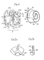
- Fig. 5 shows such an embodiment in which an annular groove 42' is formed on the surface of circular plate 301 and/or on the surface of fixed ring 371.
- the outer diameter of groove 42' is equal to the diameter dr of circular concavities 41, 42 and width of groove is selected as x.
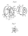
- FIG. 6 and Fig. 7 another embodiment is shown. This embodiment is directed to a modification of the thrust bearing elements between orbiting scroll member 30 and fixed plate 371.
- Sliding ring 372 is provided with the plurality of pockets 39' each of which holds a cylindrical sliding disk 43 as a substitute for balls 40 shown in Fig. 1 and Fig. 4. Both end surfaces of sliding disk 43 contact the facing surfaces of fixed ring 371 and circular plate 301.
- the thickness of sliding disk 43 is greater than the thickness of sliding ring 372. and diameter of sliding disk 43 is selected equal or slightly smaller than the diameter of pockets 39', in order to prevent the radial movement thereof. If the diameter of sliding disk 43 is amaller than the diameter of pockets 39', rotation of the sliding disk therein is permitted.
- the thrust load from orbiting scroll member 30 is supported on the fixed ring 371 through sliding disks 43.
- sliding disks 43 contact with the surface of fixed ring 371 and circular plate 301, and the sliding disks 43 thereby slide thereon.
- sliding disks 43 and the surface of fixed ring 371 and circular plate 301 be comprised of a bearing metal or aluminum alloy, lead, bronze or a self-lubricating metal or that an adequate coating with sliding bearing capability be applied to the base material such as steel.
- orbiting scroll member 30 or sliding ring 371 is made of aluminum or an aluminum alloy to reduce weight of compressor units, the surface of circular plate 301 or sliding ring 371 may easily be worn out by the contact of ball 40 or sliding disks 43 which receive the thrust load from orbiting scroll member 30. Whereby, it is desirable that sheet metal 44 made of material such as the bearing metal, be disposed as the contact surface of one or both of the circular plate 301 and the fixed ring 371.
- the pockets 39 and 39' are located along generally the same circumference as the keys 372. More particularly, the center of the pockets 39, 39' are located substantially on a circumferential line passing through the center of the keys 372a-d in a radial direction. The guiding effect of the key 372a-d and the thrust bearing effect of the balls 40 or the sliding disks 43 are thereby located on substantially the same circumference, which is adjacent the outer perimeter of the orbiting scroll member 30.
- a bearing element in the form of a ball 40, is dimensioned relative to the spacing between the keyways 371a-b, 301a-b, and relative to the total dimension of the ring 372 between the outer surfaces of opposing keys 372a-b and 372c-d such that the axial thrust of the orbiting scroll member during normal orbrting motion is received totally by the bearing elements and, hence not by keys.
- the diameter of ball 40, and hence, the space between fixed ring 371 and the circular plate 301 of orbiting scroll member 30 is shown as db.
- the bearing element is shown in contact with a flat surface of the fixed ring 371 and of the circular plate 301 of orbiting scroll member 30.
- the bearing element can be received within an indentation or annular groove.
- the space between the outermost or bottommost surfaces of the keyways 371a-b, 301a-b is shown as S 1 .
- the height or thickness of each key is shown as t 2
- the thickness of the remaining portion of the sliding ring 372 is shown as t l .
- the depth of the keyways 371a-b, 301a-b can be equal to t 2 . So that the axial thrust is received solely by bearing elements during normal orbiting of motion, the overall thickness of the sliding ring 372 and the keys extending therefrom is less than the spacing between facing keyways 371a-b, 301a, i.e.
- t 1 2t 2 is less than S 1 ; and the thickness t 2 of each key 372a to 372d is less than the diameter or thickness of the bearing elements minus the thickness of the sliding ring, i.e. t 2 is less than db - t l .
Abstract
Description
- This invention relates to scroll-type fluid displacement apparatus.
- Scroll-type apparatus are well known in the prior art.
- For example, U.S. Patent No. 801,182, discloses a device including two scroll members each having an end plate and a spiroidal or involute spiral element. The scroll members are maintained angularly and radially offset so that both spiral elements interfit at a plurality of line contacts between their spiral curved surfaces, to thereby seal off and define at least one pair of fluid pockets. The relative orbital motion of these scroll members shifts the line contact along the spiral curved surfaces and, therefore, changes the volume in the fluid pockets. The volume of the fluid pockets increases or decreases dependent on the direction of orbital motion. Therefore, a scroll type apparatus is applicable to compress, expand or pump fluids.
- Sealing along the line contact must be maintained because the fluid pockets are restricted or defined by the line contact between the two spiral elements and, as line contact shifts along the surface of spiral elements, the fluid pocket changes volume by the relative orbital motion of the scroll members. In some prior art devices, both scroll members are supported on a crank pin or shaft which is disposed at end portions of drive shafts to accomplish the relative orbital motion between the scroll members. The scroll members are thereby supported in a cantilever manner. Therefore, a slant may arise between the drive shafts and the cantilever supported scroll members, whereby axial line contact between the spiral elements is not maintained. In other prior art devices one of the scroll members is fixedly disposed in a housing and the axial slant of the scroll member is thereby prevented. However, the other scroll member must be supported on the crank pin of the drive shaft, therefore, axial slant of this scroll member by the cantilever support is not resolved. In addition, the movement of the orbiting scroll member is not rotary motion around the center of the scroll member, but is orbiting motion caused by the eccentrical movement of the crank pin moved by the rotation of the drive shaft, therefore axial slant easily arises. When the axial slant occurs several problems arise; primarily sealing of the line contact, vibration of the apparatus during operation and noise caused by striking of the spiral elements.
- It is a primary object of this invention to provide a scroll-type fluid apparatus wherein a rotation preventing mechanism of the orbiting scroll member is provided with a mechanism for preventing axial slant of the orbiting scroll member.
- Another object of this invention is to provide a small size and vibration-less scroll-type apparatus wherein sealing of the fluid pocket is secured.
- Still another object of this invention is to provide a scroll-type apparatus which is simple in construction, yet realizing the above described objects.
- According to the present invention there is provided a scroll-type fluid displacement apparatus including a housing having a fluid inlet port and a fluid outlet port, a fixed scroll member fixedly disposed relative to said housing and having an end surface from which first wrap means extends into the interior of said housing, an orbiting scroll member having end plate means from which second wrap means extends, said first and second wrap means interfitting at an angular offset to make a plurality of line contacts to define at least one pair of sealed off fluid pockets, a drive mechanism connected to said orbiting scroll member for transmitting orbital motion to said orbiting scroll member, and rotation preventing means for preventing rotation of said orbiting scroll member during the orbital motion of said orbiting scroll member, whereby said fluid pockets change volume by the orbital motion of said orbiting scroll member, wherein said rotation preventing means comprise a fixed ring disposed within said housing, spaced from and opposed to said end plate means, and a sliding ring which is slidably connected to said fixed ring by keys and keyways, thereby to permit relative motion in a first direction parallel with a diameter and slidably connected to said end plate means by keys and keyways, thereby to permit relative motion in a second direction perpendicular to said first direction, said sliding ring has formed therein a plurality of pockets which penetrate axially and are circumferentially spaced, said pockets retain bearing elements for transmitting an axial thrust load from said orbiting scroll member to said fixed ring, and said bearing elements comprise cylindrical pins or circular discs.
- A preferred scroll-type fluid displacement apparatus according to this invention include's a housing having a fluid inlet port and a fluid outlet port. A fixed scroll member is fixedly disposed within the housing and has first end plate means from which a first wrap extend. An orbiting scroll member has a second end plate means from which second wrap means extend. The first and second wrap means interfit at an angular offset to make a plurality of line contacts to define at least one pair of sealed off fluid pockets. A drive mechanism is connected to the orbiting scroll member to transmit orbital motion to the orbiting scroll member. The fluid pockets change volume due to the orbital motion of the orbiting scroll member. A rotation preventing/thrust bearing means is disposed in the housing, for preventing the rotation of the orbiting scroll member but still allowing the orbital motion of the orbiting scroll member. The rotation preventing/thrust bearing means is comprised of a fixed ring and a sliding ring. The fixed ring is secured to the inner surface of the housing and is opposed to the second end plate of the orbiting scroll member. The sliding ring is disposed in a hollow space between the fixed ring and the second end plate and is slidably connected to the fixed ring by keys and keyways for movement in a first direction of a diameter. The sliding ring is also slidably connected to the second end plate means by keys and keyways for movement in a second direction of a diameter perpendicular to the first direction. The sliding ring is formed with a plurality of spaced axial penetrating pockets. The pockets retain a bearing element, whereby the thrust load from the orbiting scroll member is supported on the fixed ring through the bearing elements.
- In one embodiment of the invention, the bearing elements are comprised of a plurality of sliding discs. The sliding discs are held in the pockets and have two parallel end surfaces. One end surface contacts the surface of the fixed ring and the other end surface contacts the second end plate means. The sliding disks are thereby held in such a manner that radial movement of the sliding disks within the pockets is prevented, while rotation of the sliding disks within the pockets is permitted.
- The invention will now be described, by way of example, with reference to the accompanying drawings, in which:-
- Fig. 1 shows a vertical sectional view of a compressor unit of the scroll type according to an embodiment of this invention;
- Fig. 2 is an exploded perspective view of the driving mechanism in the embodiment of Fig. 1;
- Fig. 3 is a sectional view taken along line III-III in Fig. 1;
- Fig. 4 is an exploded perspective view of an embodiment of a rotation preventing mechanism of this invention;
- Fig. 5(a) and 5(b) are respectively plan and sectional views of a fixed ring of a rotation prevention mechanism;
- Fig. 6 is a view similar to Fig. 4, illustrating another embodiment of a rotation preventing mechanism;
- Fig. 7 is a sectional view through the rotation preventing mechanism of Fig. 6; and
- Fig. & is a diagramatic cross-sectional view of an embodiment of a rotation preventing mechanism, illustrating relative spacing and dimensions of the elements of the mechanism.
- Referring to Fig. 1, a fluid displacement apparatus in accordance with the present invention, in particular a refrigerant compressor unit 1 of an embodiment of the present invention is shown. The unit 1 includes a
compressor housing 10 comprising acylindrical housing 11, a front end plate 12 disposed to front end portion of thecylindrical housing 11 and arear end plate 13 disposed to a rear end portion of thecylindrical housing 11. An opening is formed in rront end plate 12 and adrive shaft 15 is rotatably supported by a ball bearing 14 which is disposed in the opening. Front end plate 12 has asleeve portion 16 projecting from the front surface thereof and surroundingdrive shaft 15 to define a shaft seal cavity. Ashaft seal assembly 17 is assembled ondrive shaft 15 within the shaft seal cavity. Apully 19 is rotatably supported by abearing means 18 which is disposed on outer surface ofsleeve portion 16. An electromagneticannular coil 20 is fixed to the outer surface ofsleeve portion 16 and is received in an annular cavity of thepulley 19. Anarmature plate 21 is elastically supported on the outer end of thedrive shaft 15 which extends fromsleeve portion 16. A magneticclutch comprising pulley 19,magnetic coil 20 andarmature plate 21 is thereby formed. Thus,drive shaft 15 is driven by an external drive power source, for example, a motor of a vehicle, through a rotational' force transmitting means such as the magnetic clutch. - Front end plate 12 is fixed to a front end portion of
cylindrical housing 11 by a bolt (not shown), to thereby cover an opening ofcylindrical housing 11 and is sealed by an 0-ring 22.Rear end plate 13 is provided with anannular porjection 23 on its inner surface to partition asuction chamber 24 from adischarge chamber 25.Rear end plate 13 has afluid inlet port 26 and a fluid outlet port (not shown), which respectively are connected to the suction anddischarge chambers Rear end plate 13, together with acircular end plate 281, are fixed to the rear end portion ofcylindrical housing 11 by a bolt-nut 27.Circular end plate 281 of a fixedscroll member 28 is disposed in a hollow spaced betweencylindrical housing 11 andrear end plate 13 and is secured tocylindrical housing 11.Reference numberals 2 and 3 represent gaskets for preventing fluid leakage past the outer perimeter ofcircular plate 281 and betweensuction chamber 24 anddischarge chamber 25. - Fixed
scroll member 28 includes the circular end plate..281 and a wrap means orspiral element 282 affixed to or extending from one side surface ofcircular plate 281.Circular plate 281 is fixedly disposed between the rear end portion ofcylindrical housing 11 andrear end plate 13. The opening of the rear end portion ofcylindrical housing 11 is thereby covered by thecircular plate 281.Spiral element 282 is disposed in aninner chamber 29 ofcylindrical housing 11.Circular plate 281 is provided with a hole orsuction port 283 which communicates betweensuction chamber 24 andinner chamber 29 ofcylindrical housing 11. - An
orbiting scroll member 30 is also disposed in thechamber 29. Orbitingscroll member 30 also comprises acircular end plate 301 and a wrap means orspiral element 302 affixed to or extending from one side surface ofcircular plate 301. Thespiral element 302 andspiral element 282 of fixedscroll member 28 interfit at an angular offset of 1800 and at a determined radial offset. Therefore, a fluid pocket is formed between bothspiral element scroll member 30 is connected to a drive mechanism and to a rotation preventing mechanism. These last two mechanisms effect orbital motion at circular radius Ro by rotation ofdrive shaft 15, to thereby compress fluid passing through the compresser unit. - Generally, radius Ro of orbital motion is given by
- The
spiral element 302 is placed radially offset from thespiral element 282 of fixedscroll member 28 by the distance Ro. Thereby, orbitingscroll member 30 is allowed to make the orbital motion of a radius Ro by the rotation ofdrive shaft 15. As thescroll member 30 orbits, the line contact between bothspiral elements spiral elements 282, 3.02 move to the center with a consequent reduction of volume, to thereby compress the fluid in the pockets. A hole or dischargeport 282 is formed through thecircular plate 281 at a position near to the center ofspiral element 282 and is connected to dischargechamber 25. Therefore, fluid or refrigerant gas, introduced intochamber 29 from external fluid circuit throughinlet port 26,suction chamber 24 andhole 283 is taken into fluid pockets fromed between bothspiral elements scroll member 30 orbits, fluid in the fluid pockets is compressed and the compressed fluid is discharged intodischarge chamber 25 from the fluid pocket of the spiral element center throughhole 284 and therefrom, discharged through an outlet port to an external fluid circuit, for example, a cooling circuit. - Referring to Figs. 1, 2 and 3 a driving mechanism of orbiting .
scroll member 30 will be described. Driveshaft 15, which is rotatably supported by front end plate 12 through aball bearing 14 is formed with adisk portion 151.Disk portion 151 is rotatably supported byball bearing 31 which is disposed in a front end opening ofcylindrical housing 11. An inner ring of theball bearing 31 is fitted against acollar 152 formed withdisk portion 151, and the other outer ring is fitted against a collar 111 formed at front end opening ofcylindrical housing 11. An inner ring ofball bearing 14 is fitted against a steppedportion 153 of drivingshaft 15 and an outer ring ofball bearing 14 is fitted against ashoulder portion 121 of an opening of front end plate 12. Therefore, driveshaft 15 andball bearings - A crank pin or drive
pin 154 axially projects from an end surface ofdisk portion 151 and is radially offset from the center ofdrive shaft 15. -
Circular plate 301 of orbitingscroll member 30 is provided with atubular boss 303 axially projecting from an end surface ofcircular plate 301. Thespiral element 302 extends from an opposite end surface ofcircular plate 301. A discoid or shortaxial bushing 33 is fitted intoboss 303, and rotatably supported therein by bearing means, such as aneedle bearing 34.Bushing 33 has abalance weight 331 which is shaped as a portion of a disc or ring and extends radially from thebushing 33 along a front surface thereof. --Aneccentric hole 332 is formed in thebushing 33 radially offset from center of thebushing 33.Drive pin 154 is fitted into the eccentricallydisposed hole 332.Bushing 33 is therefore driven by the revolution ofdrive pin 154 and permitted to rotate by aneedle bearing 34. - Respective placement of center Os of
shaft 15, center Oc ofbushing 33, and center Od ofhole 332 and thus of drive pin 154, is shown in Fig. 3. In the position shown in Fig. 3, which positioning is shown there for purposes of explanation, the distance between Os and Oc is the radius Ro of orbital motion, and when drive pin 154 is fitted toeccentric hole 332, center Od ofdrive pin 154 is placed, with respect to Os, on the opposite side of a line Li, which is through Oc and perpendicular to a line L through Oc and Os, and also beyond the line through Oc and Os in direction of rotation A ofshaft 15. - In this construction of a driving mechanism, center Oc of
bushing 33 is permitted to swing about the center Od ofdrive pin 154 at a radius E2. When driveshaft 15 rotates drive force is exerted at the center Od to the left and reaction force of gas compression appears at the center Oc to the right, both forces being parallel to line L1. Therefore, the arm Od-Oc can swing outwardly by the creation of the moment generated by the two forces. Therefore,spiral element 302 of orbitingscroll member 30 is forced towardspiral element 282 of fixedscroll member 28, and orbitingscroll member 30 orbits with the radius Ro around center Oc ofdrive shaft 15. The rotation of orbitingscroll member 30 is prevented by rotation preventing mechanism, described more fully hereinafter, whereby orbitingscroll member 30 orbits and keeps its relative ungular relationship. The fluid pockets move because of the orbital motion of orbitingscroll member 30, to thereby compress the fluid. - When orbiting
scroll member 30 is driven throughbushing 33 havingeccentric hole 332, an urging force which acts at line contact between bothspiral element bushing 33 is rotatable around center Od ofdrive pin 154, therefore, if a pitch of a spiral element or a wall thickness of a spiral element, due to manufacturing inaccuracy or wear, has a dimentional error, distance Oc-Od can change to correspond the error. Orbitingscroll member 30, thereby, moves smoothly along the line contacts between the spiral elements. The orbital motion of orbitingscroll member 30, bearing 34 andbushing 33 causes a centrifugal force F1. - A
balance weight 331 is provided to cause centrifugal force F2 by its rotation. The mass and location ofbalance weight 331 are selected so that the centrifugal force F is equal in magnitude and opposite in direction to the centrifugal force F1. Therefore the centrifugal force F which is caused by the orbital motion of orbitingscroll member 30, bearing 34, bushing 33 will be cancelled by the centrifugal force F2, since the force F1, is equal in magnitude and opposite in direction to the force F2. - In the embodiment shown in Fig. 1, drive
shaft 15 is provided . with a pair ofbalance weights shaft 15 created by centrifugal forces F1, F2. Thebalance weights balance weights - Referring to Fig. 4 and Fig. 1, a rotation preventing means 37 will be described. Rotation preventing means 37 is disposed to surround
boss 303 and is comprised of a fixedring 371 and a slidingring 372.Fixed ring 371 is secured to a steppedportion 112 of the inner surface ofcylindrical housing 11 bypins 38.Fixed ring 371 is provided with a pair of keyways 371a, 371b in an axial end surface facing orbitingscroll member 30. Slidingring 372 is disposed in a hollow space between fixedring 371 andcircular plate 301 of orbitingscroll member 30. Slidingring 372 is provided with a pair ofkeys 372a, 372b on the surface facing fixedring 371, which are received inkeyways 371a, 371b. Therefore, slidingring 371 is slidable in the radial direction by the guide ofkeys 372a, 372b within keyways 371a, 371b. Slidingring 372 is also provided with a pair ofkeys 372c, 372d on its opposite surface.Keys 372c, 372d are arranged along a diameter perpendicular to the diameter along whichkeys 372a, 372b are arranged.Circular plate 301 of orbitingscroll member 30 is provided with a pair of keyways (one of which is shown as 301a in Fig. 4) on a surface facing slidingring 372 in which are receivedkeys 372c, 372d. The keyways ofcircular plate 301 are formed outside the diameter ofboss 303. Therefore, orbitingscroll member 30 is slidable in radial direction by guide ofkeys 372c, 372d within the keyways-of thecircular plate 301. - Accordingly, orbiting
scroll member 30 is slidable in one radial direction with slidingring 372, and is slidable in another radial direction independently. The second sliding direction is perpendicular to the first radial direction. Therefore, orbitingscroll member 20 is prevented from rotation, but is permitted to move in two radial directions perpendicular to one another. - The
keys 372a-d are fixed in position on the slidingring 372, and arc preferably formed integral with thering 372. Thekeys 372a-d each have radially extending outer surfaces oredges 373 transverse to the major surfaces of the keys which face thering 371 and theplate 301. Theedges 373 are flat along their entire length and mate with flat surfaces oredges 375 of the keyways within which they are slidably received. - According to this invention, sliding
ring 372 is provided with a plurality of circular holes or pockets 39, except in the portion of thering 372 wherekeys 372a-d arc formed.Pockets 39 penetrate axially and arc suitably spaced between adjacent keys about the perimeter of thering 372. Each of thepockets 39 retain a bcaring eiement such as aball 40. The diameter of eachball 40 is greater than the thickness of slidingring 372. Therefore, the spherical surface ofball 40 usually is in contact with and rolls on the surface of fixedring 371 andcircular plate 301. The thrust load from orbitingscroll member 30 is thus supported on fixedring 371 throughballs 40. - Sliding
ring 371 is in reciprocating motion in one radial direction, therefore, if the diameter ofball 40 is selected to be the same as the diameter ofpockets 39, theball 40 can not make rolling motion contact with regard to both surfaces ofring 371 andplate 301, and sliding motion arises. Whereby, the race surface of fixedring 371 orcircular plate 301 might be damaged, orballs 40 might be damaged due to a flaking problem. Therefore, the diameter ofpockets 39 must be selected so thatball 40 will making rolling motion while following the orbital motion of orbitingscroll member 30. Minimum diameter dp ofpockets 39 in whichball 40 is permitted rolling movement while following the orbital motion of orbitingscroll member 30 is given by dp=Ro+db, where db is the diameter ofball 40 and Ro is the radius of the orbital motion of orbitingscroll member 30. Becauseball 40 is placed between fixedring 371 and orbitingscroll member 30, and orbitingscroll member 30 makes an orbital motion with radius Ro, the traveling radius of ball 40 with regard to the race surface of the fixedring 371 is half of the radius of orbital motion of orbitingscroll member 30, in turn, it is easily seen that the diameter ofpockets 39, which must permit the rolling motion ofball 40, is the sum of the radius Ro of orbital motion and the diameter db ofball 40. - In accordance with the above embodiment of rotation preventing means 37, the race surfaces of fixed
ring 371 andcircular plate 301 may be formed in a flat surface and more than threeballs 40 mav be used. In this case, theball 40 does not always move in a circular locus of movement by action of gravity on the ball or other force such as a centrifugal force due to ball movement. In this condition,ball 40 may strike the inner wall ofpockets 39 and thereby damage the inner wall ofpockets 39 or the ball itself. - Wherepon,in accordance with the present invention as shown in Fig. 1 and Fig. 4 the surfaces of fixed
ring 371 andcircular plate 301, which opposes across theball 40, are provided withcircular indentations balls 40. The indentations have circular perimeters and preferably a flat bottom. A diameter dr of eachindentation ball 40 corresponding to the depth of indentation and/or slope of annular wall to permit the required roll motion of the travelling radius with regard to fixedring 371 andcircular plate 301 of orbitingscroll member 30. Thereby,ball 40 usually moves almost in contact along the edge of bothindentations ball 40 on the fixedring 371 and cir-eular plate 301 can be circular. From this context, the shape of the indentation on thering 371 andplate 301 may be an annular groove rather than circular concave. Fig. 5 shows such an embodiment in which an annular groove 42' is formed on the surface ofcircular plate 301 and/or on the surface of fixedring 371. The outer diameter of groove 42' is equal to the diameter dr ofcircular concavities - Referring to Fig. 6 and Fig. 7, another embodiment is shown. This embodiment is directed to a modification of the thrust bearing elements between orbiting
scroll member 30 and fixedplate 371. Slidingring 372 is provided with the plurality of pockets 39' each of which holds a cylindrical slidingdisk 43 as a substitute forballs 40 shown in Fig. 1 and Fig. 4. Both end surfaces of slidingdisk 43 contact the facing surfaces of fixedring 371 andcircular plate 301. - The thickness of sliding
disk 43 is greater than the thickness of slidingring 372. and diameter of slidingdisk 43 is selected equal or slightly smaller than the diameter of pockets 39', in order to prevent the radial movement thereof. If the diameter of slidingdisk 43 is amaller than the diameter of pockets 39', rotation of the sliding disk therein is permitted. - According to this construction, the thrust load from orbiting
scroll member 30 is supported on the fixedring 371 through slidingdisks 43. - The end surfaces of sliding
disks 43 contact with the surface of fixedring 371 andcircular plate 301, and the slidingdisks 43 thereby slide thereon. Whereby, it is desirable that slidingdisks 43 and the surface of fixedring 371 andcircular plate 301 be comprised of a bearing metal or aluminum alloy, lead, bronze or a self-lubricating metal or that an adequate coating with sliding bearing capability be applied to the base material such as steel. - If orbiting
scroll member 30 or slidingring 371 is made of aluminum or an aluminum alloy to reduce weight of compressor units, the surface ofcircular plate 301 or slidingring 371 may easily be worn out by the contact ofball 40 or slidingdisks 43 which receive the thrust load from orbitingscroll member 30. Whereby, it is desirable thatsheet metal 44 made of material such as the bearing metal, be disposed as the contact surface of one or both of thecircular plate 301 and the fixedring 371. - As seen in Fig. 4 and Fig. 6 the
pockets 39 and 39' are located along generally the same circumference as thekeys 372. More particularly, the center of thepockets 39, 39' are located substantially on a circumferential line passing through the center of thekeys 372a-d in a radial direction. The guiding effect of the key 372a-d and the thrust bearing effect of theballs 40 or the slidingdisks 43 are thereby located on substantially the same circumference, which is adjacent the outer perimeter of theorbiting scroll member 30. - As illustrated in Fig. 8, a bearing element, in the form of a
ball 40, is dimensioned relative to the spacing between thekeyways 371a-b, 301a-b, and relative to the total dimension of thering 372 between the outer surfaces of opposingkeys 372a-b and 372c-d such that the axial thrust of the orbiting scroll member during normal orbrting motion is received totally by the bearing elements and, hence not by keys. The diameter ofball 40, and hence, the space between fixedring 371 and thecircular plate 301 of orbitingscroll member 30 is shown as db. In Fig. 8, the bearing element is shown in contact with a flat surface of the fixedring 371 and of thecircular plate 301 of orbitingscroll member 30. In other embodiments, the bearing element can be received within an indentation or annular groove. The space between the outermost or bottommost surfaces of thekeyways 371a-b, 301a-b is shown as S1. The height or thickness of each key is shown as t2, and the thickness of the remaining portion of the slidingring 372 is shown as tl. The depth of thekeyways 371a-b, 301a-b can be equal to t2. So that the axial thrust is received solely by bearing elements during normal orbiting of motion, the overall thickness of the slidingring 372 and the keys extending therefrom is less than the spacing between facingkeyways 371a-b, 301a, i.e. t 1 2t2 is less than S1; and the thickness t2 of each key 372a to 372d is less than the diameter or thickness of the bearing elements minus the thickness of the sliding ring, i.e. t2 is less than db - tl. - This invention has been described in detail in connection with preferred embodiments, but these are examples only and this invention is not restricted thereto. It will be easily understood by those skilled in the art that the other variations and modifications can be easily made within the scope of this invention.
Claims (14)
Applications Claiming Priority (2)
| Application Number | Priority Date | Filing Date | Title |
|---|---|---|---|
| JP44072/80 | 1980-04-05 | ||
| JP4407280A JPS56141087A (en) | 1980-04-05 | 1980-04-05 | Scroll type compressor |
Related Parent Applications (2)
| Application Number | Title | Priority Date | Filing Date |
|---|---|---|---|
| EP81301474.3 Division | 1981-04-03 | ||
| EP81301474A Division EP0038152B1 (en) | 1980-04-05 | 1981-04-03 | Improvements in scroll-type fluid displacement apparatus |
Publications (2)
| Publication Number | Publication Date |
|---|---|
| EP0090931A2 true EP0090931A2 (en) | 1983-10-12 |
| EP0090931A3 EP0090931A3 (en) | 1984-05-09 |
Family
ID=12681419
Family Applications (2)
| Application Number | Title | Priority Date | Filing Date |
|---|---|---|---|
| EP83101502A Withdrawn EP0090931A3 (en) | 1980-04-05 | 1981-04-03 | Movement synchronizing means for scroll-type fluid displacement apparatus |
| EP81301474A Expired EP0038152B1 (en) | 1980-04-05 | 1981-04-03 | Improvements in scroll-type fluid displacement apparatus |
Family Applications After (1)
| Application Number | Title | Priority Date | Filing Date |
|---|---|---|---|
| EP81301474A Expired EP0038152B1 (en) | 1980-04-05 | 1981-04-03 | Improvements in scroll-type fluid displacement apparatus |
Country Status (6)
| Country | Link |
|---|---|
| US (1) | US4406600A (en) |
| EP (2) | EP0090931A3 (en) |
| JP (1) | JPS56141087A (en) |
| AU (1) | AU543181B2 (en) |
| CA (1) | CA1222983A (en) |
| DE (1) | DE3171190D1 (en) |
Cited By (2)
| Publication number | Priority date | Publication date | Assignee | Title |
|---|---|---|---|---|
| EP1059452A1 (en) * | 1999-06-08 | 2000-12-13 | Mitsubishi Heavy Industries, Ltd. | Thrust ball bearing and open-type scroll compressor |
| GB2617117A (en) * | 2022-03-30 | 2023-10-04 | Edwards Ltd | Scroll pump |
Families Citing this family (36)
| Publication number | Priority date | Publication date | Assignee | Title |
|---|---|---|---|---|
| JPS6022199B2 (en) * | 1981-03-09 | 1985-05-31 | サンデン株式会社 | Scroll compressor |
| JPS57148087A (en) * | 1981-03-09 | 1982-09-13 | Sanden Corp | Scroll type compressor |
| JPS5862396A (en) * | 1981-10-12 | 1983-04-13 | Sanden Corp | Fluid machine |
| JPS5928082A (en) * | 1982-08-07 | 1984-02-14 | Sanden Corp | Revolving piston type fluid machine |
| JPS5979086A (en) * | 1982-10-27 | 1984-05-08 | Hitachi Ltd | Scroll hydraulic machine |
| GB2132276B (en) * | 1982-12-23 | 1986-10-01 | Copeland Corp | Scroll-type rotary fluid-machine |
| JPS59142483U (en) * | 1983-03-15 | 1984-09-22 | サンデン株式会社 | Rotation prevention mechanism for scroll compressor |
| JPS59196745A (en) * | 1983-03-31 | 1984-11-08 | Res Assoc Residual Oil Process<Rarop> | Iron-contg. zeolite composition |
| JPS60111080A (en) * | 1983-11-19 | 1985-06-17 | Sanden Corp | Scroll type compressor |
| JPS6214186U (en) * | 1985-07-12 | 1987-01-28 | ||
| JPH03105088A (en) * | 1989-09-18 | 1991-05-01 | Sanden Corp | Scroll type compressor |
| CA2063888C (en) * | 1991-04-26 | 2001-08-07 | Hubert Richardson Jr. | Orbiting rotary compressor |
| US5236318A (en) * | 1991-10-18 | 1993-08-17 | Tecumseh Products Company | Orbiting rotary compressor with adjustable eccentric |
| JPH0630486U (en) * | 1992-09-21 | 1994-04-22 | サンデン株式会社 | Scroll compressor |
| KR940007377A (en) * | 1992-09-30 | 1994-04-27 | 이소가이 찌세이 | Scroll compressor |
| JPH0649783U (en) * | 1992-12-07 | 1994-07-08 | サンデン株式会社 | Scroll fluid machinery |
| US5470213A (en) * | 1993-04-13 | 1995-11-28 | Kabushiki Kaisha Toyoda Jidoshokki Seisakusho | Scroll type compressor having a ring for compressive force transmission and orbit determination |
| US5462418A (en) * | 1993-04-13 | 1995-10-31 | Kabushiki Kaisha Toyoda Jidoshokki Seisakusho | Scroll type compressor equipped with mechanism for receiving reaction force of compressed gas |
| TW381147B (en) * | 1994-07-22 | 2000-02-01 | Mitsubishi Electric Corp | Scroll compressor |
| JP3017641B2 (en) * | 1994-07-27 | 2000-03-13 | 株式会社豊田自動織機製作所 | Scroll compressor |
| US5813843A (en) * | 1995-05-24 | 1998-09-29 | Tokico Ltd. | Scroll-type fluidic machine having a slider for axial thrust and rotation prevention |
| JP3053551B2 (en) * | 1995-08-03 | 2000-06-19 | サンデン株式会社 | Ball coupling |
| JPH09250464A (en) * | 1996-03-18 | 1997-09-22 | Sanden Corp | Auto-rotation prevension mechanism used for scroll type compressor |
| JPH09303275A (en) * | 1996-05-10 | 1997-11-25 | Sanden Corp | Scroll compressor |
| JPH09303274A (en) * | 1996-05-15 | 1997-11-25 | Sanden Corp | Scroll type compressor |
| JP3136267B2 (en) * | 1996-05-21 | 2001-02-19 | サンデン株式会社 | Anti-rotation mechanism of scroll compressor |
| JP3762494B2 (en) * | 1996-10-22 | 2006-04-05 | サンデン株式会社 | Scroll type fluid machinery |
| JPH1122658A (en) * | 1997-07-04 | 1999-01-26 | Sanden Corp | Scroll compressor |
| JP3115553B2 (en) * | 1998-01-27 | 2000-12-11 | サンデン株式会社 | A mechanism for preventing rotation of a movable scroll in a scroll-type fluid machine |
| JPH11241690A (en) * | 1998-02-26 | 1999-09-07 | Sanden Corp | Scroll type fluid machinery |
| JP2000055040A (en) | 1998-08-04 | 2000-02-22 | Sanden Corp | Ball coupling |
| JP3249781B2 (en) * | 1998-08-05 | 2002-01-21 | サンデン株式会社 | Thrust ball bearings |
| JP2001132664A (en) | 1999-11-04 | 2001-05-18 | Sanden Corp | Scroll compressor |
| US6302664B1 (en) * | 2000-05-31 | 2001-10-16 | Westinghouse Air Brake Company | Oilers rotary scroll air compressor axial loading support for orbiting member |
| US6283737B1 (en) * | 2000-06-01 | 2001-09-04 | Westinghouse Air Brake Technologies Corporation | Oiless rotary scroll air compressor antirotation assembly |
| JP2007291879A (en) * | 2006-04-21 | 2007-11-08 | Sanden Corp | Scroll type fluid machine |
Citations (3)
| Publication number | Priority date | Publication date | Assignee | Title |
|---|---|---|---|---|
| FR55178E (en) * | 1946-12-13 | 1951-10-02 | Rotary machine functioning as a pump, compressor, etc. | |
| US4065279A (en) * | 1976-09-13 | 1977-12-27 | Arthur D. Little, Inc. | Scroll-type apparatus with hydrodynamic thrust bearing |
| US4082484A (en) * | 1977-01-24 | 1978-04-04 | Arthur D. Little, Inc. | Scroll-type apparatus with fixed throw crank drive mechanism |
Family Cites Families (6)
| Publication number | Priority date | Publication date | Assignee | Title |
|---|---|---|---|---|
| US2813409A (en) * | 1954-11-08 | 1957-11-19 | Victor Lundy | Universal coupling |
| US3924977A (en) * | 1973-06-11 | 1975-12-09 | Little Inc A | Positive fluid displacement apparatus |
| US4121438A (en) * | 1976-09-13 | 1978-10-24 | Arthur D. Little, Inc. | Coupling member for orbiting machinery |
| US4259043A (en) * | 1977-06-17 | 1981-03-31 | Arthur D. Little, Inc. | Thrust bearing/coupling component for orbiting scroll-type machinery and scroll-type machinery incorporating the same |
| US4160629A (en) * | 1977-06-17 | 1979-07-10 | Arthur D. Little, Inc. | Liquid immersible scroll pump |
| BE870198A (en) * | 1978-09-05 | 1979-03-05 | Little Inc A | ADDITIONAL VOLUTE ELEMENTS, ESPECIALLY FOR LIQUID PUMPS |
-
1980
- 1980-04-05 JP JP4407280A patent/JPS56141087A/en active Pending
-
1981
- 1981-03-31 US US06/249,656 patent/US4406600A/en not_active Expired - Lifetime
- 1981-04-01 AU AU69011/81A patent/AU543181B2/en not_active Expired
- 1981-04-03 EP EP83101502A patent/EP0090931A3/en not_active Withdrawn
- 1981-04-03 DE DE8181301474T patent/DE3171190D1/en not_active Expired
- 1981-04-03 EP EP81301474A patent/EP0038152B1/en not_active Expired
- 1981-04-06 CA CA000374722A patent/CA1222983A/en not_active Expired
Patent Citations (4)
| Publication number | Priority date | Publication date | Assignee | Title |
|---|---|---|---|---|
| FR55178E (en) * | 1946-12-13 | 1951-10-02 | Rotary machine functioning as a pump, compressor, etc. | |
| US4065279A (en) * | 1976-09-13 | 1977-12-27 | Arthur D. Little, Inc. | Scroll-type apparatus with hydrodynamic thrust bearing |
| US4082484A (en) * | 1977-01-24 | 1978-04-04 | Arthur D. Little, Inc. | Scroll-type apparatus with fixed throw crank drive mechanism |
| US4082484B1 (en) * | 1977-01-24 | 1983-06-21 |
Cited By (3)
| Publication number | Priority date | Publication date | Assignee | Title |
|---|---|---|---|---|
| EP1059452A1 (en) * | 1999-06-08 | 2000-12-13 | Mitsubishi Heavy Industries, Ltd. | Thrust ball bearing and open-type scroll compressor |
| US6312235B1 (en) | 1999-06-08 | 2001-11-06 | Mitsubishi Heavy Industries, Ltd. | Thrust ball bearing and open-type scroll compressor |
| GB2617117A (en) * | 2022-03-30 | 2023-10-04 | Edwards Ltd | Scroll pump |
Also Published As
| Publication number | Publication date |
|---|---|
| EP0090931A3 (en) | 1984-05-09 |
| AU543181B2 (en) | 1985-04-04 |
| US4406600A (en) | 1983-09-27 |
| CA1222983A (en) | 1987-06-16 |
| EP0038152A1 (en) | 1981-10-21 |
| JPS56141087A (en) | 1981-11-04 |
| DE3171190D1 (en) | 1985-08-08 |
| AU6901181A (en) | 1981-10-15 |
| EP0038152B1 (en) | 1985-07-03 |
Similar Documents
| Publication | Publication Date | Title |
|---|---|---|
| US4406600A (en) | Scroll-type fluid displacement apparatus with rotation prevention/thrust bearing means for orbiting scroll member | |
| EP0037728B1 (en) | Improvements in scroll-type fluid compressors | |
| EP0061698B1 (en) | Orbiting piston type fluid displacement apparatus with a rotation preventing device | |
| EP0059925B1 (en) | Drive mechanism for a scroll type fluid displacement apparatus | |
| EP0091544A2 (en) | Movement synchronizing means for scroll-type fluid displacement apparatus | |
| US4589828A (en) | Rotation preventing device for an orbiting member of a fluid displacement apparatus | |
| EP0066457B1 (en) | Driving support mechanism for an orbiting scroll of a scroll type fluid displacement apparatus | |
| EP0052461B1 (en) | Scroll-type fluid displacement apparatus with means for counteracting centrifugal forces | |
| CA1278782C (en) | Axial thrust load mechanism for a scroll type fluid displacement apparatus | |
| EP0060495B1 (en) | An improved rotation preventing device for an orbiting piston type fluid apparatus | |
| US4492543A (en) | Orbiting member fluid displacement apparatus with rotation preventing mechanism | |
| US4645435A (en) | Rotation preventing device for an orbiting member of a fluid displacement apparatus | |
| EP0099740B1 (en) | Scroll type fluid displacement apparatus and method of assembly | |
| EP0419204B1 (en) | Orbiting member fluid displacement apparatus with rotation preventing mechanism | |
| EP0123407B1 (en) | Rotation-preventing device for an orbiting piston-type fluid displacement apparatus | |
| US5435706A (en) | Orbiting member fluid displacement apparatus with rotation preventing mechanism | |
| EP0065261A2 (en) | Axial sealing mechanism for scroll type fluid displacement apparatus | |
| EP0039622A1 (en) | Improvements in or relating to fluid displacement apparatus | |
| EP0075053A1 (en) | Wear-resisting means for scroll-type fluid-displacement apparatuses | |
| EP0627559B1 (en) | Inspection system for a defective rotation preventing device in an orbiting member of a fluid displacement apparatus | |
| CA2279478A1 (en) | Rotation preventing device for orbiting member of fluid displacement apparatus | |
| GB2167131A (en) | Scroll-type rotary fluid-machine |
Legal Events
| Date | Code | Title | Description |
|---|---|---|---|
| PUAI | Public reference made under article 153(3) epc to a published international application that has entered the european phase |
Free format text: ORIGINAL CODE: 0009012 |
|
| AC | Divisional application: reference to earlier application |
Ref document number: 38152 Country of ref document: EP |
|
| AK | Designated contracting states |
Designated state(s): DE FR GB IT SE |
|
| PUAL | Search report despatched |
Free format text: ORIGINAL CODE: 0009013 |
|
| AK | Designated contracting states |
Designated state(s): DE FR GB IT SE |
|
| 17P | Request for examination filed |
Effective date: 19841105 |
|
| STAA | Information on the status of an ep patent application or granted ep patent |
Free format text: STATUS: THE APPLICATION IS DEEMED TO BE WITHDRAWN |
|
| 18D | Application deemed to be withdrawn |
Effective date: 19870409 |
|
| RIN1 | Information on inventor provided before grant (corrected) |
Inventor name: SAKAMOTO, SEIICHI Inventor name: TERAUCHI, KIYOSHI |