EP0806550B1 - Valve timing control device - Google Patents
Valve timing control device Download PDFInfo
- Publication number
- EP0806550B1 EP0806550B1 EP97302104A EP97302104A EP0806550B1 EP 0806550 B1 EP0806550 B1 EP 0806550B1 EP 97302104 A EP97302104 A EP 97302104A EP 97302104 A EP97302104 A EP 97302104A EP 0806550 B1 EP0806550 B1 EP 0806550B1
- Authority
- EP
- European Patent Office
- Prior art keywords
- rotor
- valve timing
- spring
- coil
- timing control
- Prior art date
- Legal status (The legal status is an assumption and is not a legal conclusion. Google has not performed a legal analysis and makes no representation as to the accuracy of the status listed.)
- Expired - Lifetime
Links
Images


Classifications
-
- F—MECHANICAL ENGINEERING; LIGHTING; HEATING; WEAPONS; BLASTING
- F01—MACHINES OR ENGINES IN GENERAL; ENGINE PLANTS IN GENERAL; STEAM ENGINES
- F01L—CYCLICALLY OPERATING VALVES FOR MACHINES OR ENGINES
- F01L1/00—Valve-gear or valve arrangements, e.g. lift-valve gear
- F01L1/34—Valve-gear or valve arrangements, e.g. lift-valve gear characterised by the provision of means for changing the timing of the valves without changing the duration of opening and without affecting the magnitude of the valve lift
- F01L1/344—Valve-gear or valve arrangements, e.g. lift-valve gear characterised by the provision of means for changing the timing of the valves without changing the duration of opening and without affecting the magnitude of the valve lift changing the angular relationship between crankshaft and camshaft, e.g. using helicoidal gear
- F01L1/3442—Valve-gear or valve arrangements, e.g. lift-valve gear characterised by the provision of means for changing the timing of the valves without changing the duration of opening and without affecting the magnitude of the valve lift changing the angular relationship between crankshaft and camshaft, e.g. using helicoidal gear using hydraulic chambers with variable volume to transmit the rotating force
- F01L2001/34423—Details relating to the hydraulic feeding circuit
- F01L2001/34446—Fluid accumulators for the feeding circuit
-
- F—MECHANICAL ENGINEERING; LIGHTING; HEATING; WEAPONS; BLASTING
- F01—MACHINES OR ENGINES IN GENERAL; ENGINE PLANTS IN GENERAL; STEAM ENGINES
- F01L—CYCLICALLY OPERATING VALVES FOR MACHINES OR ENGINES
- F01L1/00—Valve-gear or valve arrangements, e.g. lift-valve gear
- F01L1/34—Valve-gear or valve arrangements, e.g. lift-valve gear characterised by the provision of means for changing the timing of the valves without changing the duration of opening and without affecting the magnitude of the valve lift
- F01L1/344—Valve-gear or valve arrangements, e.g. lift-valve gear characterised by the provision of means for changing the timing of the valves without changing the duration of opening and without affecting the magnitude of the valve lift changing the angular relationship between crankshaft and camshaft, e.g. using helicoidal gear
- F01L1/3442—Valve-gear or valve arrangements, e.g. lift-valve gear characterised by the provision of means for changing the timing of the valves without changing the duration of opening and without affecting the magnitude of the valve lift changing the angular relationship between crankshaft and camshaft, e.g. using helicoidal gear using hydraulic chambers with variable volume to transmit the rotating force
- F01L2001/3445—Details relating to the hydraulic means for changing the angular relationship
- F01L2001/34483—Phaser return springs
Definitions
- the present invention relates to a valve timing control device and in particular to the valve timing control device for controlling an angular phase difference between a crank shaft of a combustion engine and a cam shaft of the combustion engine.
- valve timing of a combustion engine is determined by valve mechanisms driven by cam shafts according to a characteristic of the combustion engine or a specification of the combustion engine. Since a condition of the combustion is changed in response to the rotational speed of the combustion engine, however, it is difficult to obtain optimum valve timing through the whole rotational range. Therefore, a valve timing control device which is able to change valve timing in response to the condition of the combustion engine has been proposed as an auxiliary mechanism of the valve mechanism in recent years.
- a conventional device of this kind is disclosed, for example, in U.S. Patent No. 4,858,572.
- This device includes a rotor which is fixed on the cam shaft, a drive member which is driven by the rotational torque from a crank shaft and which is rotatably mounted on the cam shaft so as to surround the rotor, a plurality of chambers which are defined between the drive member and the rotor and each of which has a pair of. circumferentially opposed walls and a plurality of vanes which are mounted to the rotor and which extend outwardly therefrom in the radial direction into the chambers so as to divide each of the chambers into a first pressure chamber and a second pressure chamber.
- fluid under pressure is supplied to a selected one of the first pressure chamber and the second pressure chamber in response to the running condition of the combustion engine and an angular phase difference between the crank shaft and the cam shaft is controlled so as to advance or retard the valve timing relative to the crank shaft.
- the fluid under pressure is delivered from an oil pump.
- the valve timing control device is in the maximum advanced condition when each of the vanes contacts with one of the opposed walls of each of the chambers.
- the valve timing control device is in the maximum retarded condition when each of the vanes contacts with the other of the opposed walls of each of the chambers.
- the opening and closing timing of the exhaust valves is delayed because of the above operation of retarding the valve timing. It makes an overlap phenomenon bigger.
- the overlap phenomenon means the exhaust valves and the intake valves are opening at the same time.
- a valve timing control device comprising: a rotor fixed on a cam shaft of an engine, a housing member rotatably mounted on the cam shaft so as to surround the rotor, means for driving the housing member from a rotational output of the engine; a chamber defined between the housing member and the rotor and having a pair of circumferentially opposed walls; a vane mounted on the rotor and extending outwardly therefrom in the radial direction into the chamber so as to divide the chamber into a first pressure chamber and a second pressure chamber; a fluid supplying means for supplying fluid under pressure selectively to one of the first and second pressure chambers thereby establishing a pressure differential between said pressure chambers so as to effect relative rotation between the rotor and the housing member; and means for locking the rotor and the housing member in a predetermined relative angular disposition and for selectively releasing that locking engagement; CHARACTERIZED IN THAT a spring element is provided within the device to urge the rotor towards the
- FIG. 1 to FIG. 7 show a first embodiment of the present invention.
- a valve timing control device of the first embodiment includes an exhaust cam shaft 10, a sensor plate 20, a rotor 30, a plurality of vanes 40 and a housing 50.
- the exhaust cam shaft 10 is rotatably mounted on a cylinder head 80 of an engine E.
- the exhaust cam shaft 10 has two circular grooves 14, 15. Both the circular grooves 14, 15 are formed so as to maintain a predetermined distance between each other.
- Both the sensor plate 20 and the rotor 30 are fixed to the projecting end of the exhaust cam shaft 10 by a bolt 90.
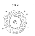
- the sensor plate 20 has three short projections 21, 22, 23 in the circumferential direction and a long projection 24 in the circumferential direction as shown FIG. 2.
- the sensor plate 20 has a rim 25.
- the rotor 30 has a plurality of grooves for inserting the vanes 40 as shown in FIG. 4 to FIG. 7.
- One side end of the housing 50 is fixed to a timing pulley 70 and the other side end of the housing 50 is fixed to a side plate 71 by a bolt 91. Therefore, the housing 50, the timing pulley 70 and the side plate 71 act in a body.
- the timing pulley 70 is transmitted rotational torque via a belt 72 (or a chain 72) from a crank shaft 83 which is rotated by the engine E.
- a pin 60 is able to connect with between the rotor 30 find the housing 50 when the rotor 30 is in phase with the housing 50.
- the exhaust cam shaft 10 has a plurality of cams (not shown). Each cam makes an exhaust valve open and close. There is a passage 11 which is formed in exhaust cam shaft 10 at its axial centre and extends in the axial direction. One end of the passage 11 communicates with the circular groove 14 through a passage 13. The circular groove 14 communicates with a passage 81 which is formed in the cylinder head 80 of the engine E. On the other hand, there are a plurality of passages 12 which are formed in the exhaust cam shaft 10 and located on a coaxial circle about the axial centre of the shaft 10 and which extend in parallel in the axial direction. One end of the passages 12 communicates with the circular groove 15. The circular groove 15 communicates with a passage 82 which is formed in the cylinder head 80 of an engine E.
- the fluid supplying device 100 comprises a changeover valve 101, a fluid pump 102 and a. controller 103.
- the changeover valve 101 is a. four port-three position type electromagnetic valve.
- the pump 102 may be a pump for lubricating the engine E.
- the passage 82 communicates with a port A of the changeover valve 101 and a passage 81 communicates with a part 8 of the changeover valve 101.
- a port P of the changeover valve 101 communicates with a discharge portion of the fluid pump 102 via a passage 105 and a port R of the changeover valve 101 communicates with a reservoir 104 via a passage 106.
- the position of the changeover valve 101 is controlled by the controller 103. in a first condition as shown in FIG.
- the discharged fluid from the pump 102 is supplied to the passage 82 and the passage 81 communicates with the reservoir 104, in a second condition all the ports A, B, P, R are interrupted; in a third condition 1 the discharged fluid from the pump 102 is supplied to the passage 81 and the passage 82 communicates with the reservoir 104) are selectively obtained.
- the controller 103 controls the above conditions of the changeover valve 101 based on parameter signals such as engine speed, the opening level of a throttle valve (not shown) and so on.
- a valve timing control mechanism V is mounted in the rotor 30 and the housing 50.
- the rotor 30 has a cylindrical shape.
- the housing 50 has an inner bore, 54 and is rotatably mounted on the outer circumferential surface of the rotor 30 so as to surround the rotor 30.
- the housing 50 has the same axial length as the rotor 30 and is provided with a plurality of grooves 51 which are outwardly extended from the inner bore 54 in the radial direction and which are separated in the circumferential direction at regular intervals
- the housing 50 is also provided with a plurality of holes 53 for penetration of the bolt 91. The holes 53 penetrate in the axial direction and are separated in the circumferential direction at regular intervals.
- a plurality of chambers RO which are separated in the circumferential direction at regular intervals and each of which has a pair of circumferentially opposed walls 55 and 56 are defined along the rotor 30, the housing 50, the timing pulley 70 and the side plate 71.
- the number of grooves 31 is equal to the number of chambers RO.
- Each of the grooves 31 extends inwardly therefrom in the radial direction.
- the grooves are located at regular intervals in the circumferential direction.
- the vanes that extend outwardly in the radial direction into the chambers RO are mounted in the grooves 31.
- each of the chambers RO is divided into a first pressure chamber R1 and a second pressure chamber R2, both of which are fluidtightly separated from each other.
- the housing 50 has a hole 52 which extends in the radial direction.
- the hole 52 is able to accommodate the pin 60 which is pushed towards the rotor 30 by a coil-spring 61.
- the coil-spring 61 is supported by a clip 63 through a retainer 62.
- the rotor 30 on its outer circumferential surface has a hole 32 which extends inwardly thereof in the radial direction so as to accommodate the pin 60.
- the rotor 30 is provided with a plurality of first passages 34, a plurality of second passages 36, and a passage 35.
- the first passages 34 and the passage 35 are in communication.
- One end of each of the first passages 34 communicates with the passage 11 and the other end of the first passages 34 communicates with each of the first chambers R1.
- one end of each of the second passages 36 communicates with the passage 12 and the other end of the second passages communicates with each of the second chambers R2.
- coil-spring 92 There is a coil-spring 92. One end of the coil-spring 92 is connected with the rotor 30 and the other end of the coil-spring 92 is connected with the side plate 71 which is fixed to the housing 50. The outer surface of the rim 25 of the sensor plate 20 guides the coil portion of the coil-spring 92 as shown in FIG. 1.
- valve timing control device having the above structure
- the exhaust camshaft 10 is rotated counterclockwise by timing pulley 70. Thereby, exhaust valves (not shown) are opened and closed.
- the pressure of the fluid delivered from the oil pump 102 is increased. Fluid under the resulting pressure is supplied to the changeover valve 101.
- the changeover valve 101 is in the first condition as shown in FIG. 1, fluid is supplied to the chambers R2 via the passage 82, the passage 12 and second passages 36.
- the vanes 40 are rotated in the counterclockwise direction, together with the rotor 30 and the exhaust cam shaft 10.
- the cam shaft 10 is advanced through an angle relative to the crank shaft 83.
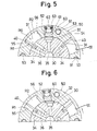
- the vanes 40 are rotated in the clockwise direction by supplying fluid under pressure to the chambers R1 via the passage 81, the passage 11 and the first passages 34. Since the first passage 34 communicates with the passage 35, fluid under pressure supplied into the hole 32 urges the pin 60 fully into the hole 52 of the housing 50 as shown in FIG. 5, thereby releasing the connection between the rotor 30 and the housing 50. With increasing pressure in the chamber R1, the vanes 40 are rotated in the clockwise direction as shown in FIG. 7 via the condition shown in FIG. 6. During the retarding rotary movement of the vanes 40, fluid in each of chambers R2 is drained to the reservoir 104 through the passage 36, the passage 12, second passages 82 and the changeover valve 101.
- the fluid pressure in the chambers R1 and R2 is drained with the elapse of time through a non-illustrated clearance between the parts, for example, between the exhaust cam shaft 10 and the cylinder head 80. Therefore, the coil-spring urges the rotor 30 in the counterclockwise direction so as to fit the pin 60 into the hole 32 of the rotor 30.
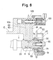
- FIG. 8 illustrates a second embodiment, which specifically is a modified arrangement of a coil-spring 93.
- the coil-spring 93 is arranged within the housing 50 between the rotor 30 and the timing pulley 70.
- the timing pulley 70 has a cylindrical hollow 74.
- the cylindrical hollow 74 accommodates the coil-spring 93 which one end thereof is connected with the rotor 30 and which the other end thereof is connected with the timing pulley 70 which is fixed to the housing 50.
Landscapes
- Engineering & Computer Science (AREA)
- Mechanical Engineering (AREA)
- General Engineering & Computer Science (AREA)
- Valve Device For Special Equipments (AREA)
- Valve-Gear Or Valve Arrangements (AREA)
Description
- The present invention relates to a valve timing control device and in particular to the valve timing control device for controlling an angular phase difference between a crank shaft of a combustion engine and a cam shaft of the combustion engine.
- In general, valve timing of a combustion engine is determined by valve mechanisms driven by cam shafts according to a characteristic of the combustion engine or a specification of the combustion engine. Since a condition of the combustion is changed in response to the rotational speed of the combustion engine, however, it is difficult to obtain optimum valve timing through the whole rotational range. Therefore, a valve timing control device which is able to change valve timing in response to the condition of the combustion engine has been proposed as an auxiliary mechanism of the valve mechanism in recent years.
- A conventional device of this kind is disclosed, for example, in U.S. Patent No. 4,858,572. This device includes a rotor which is fixed on the cam shaft, a drive member which is driven by the rotational torque from a crank shaft and which is rotatably mounted on the cam shaft so as to surround the rotor, a plurality of chambers which are defined between the drive member and the rotor and each of which has a pair of. circumferentially opposed walls and a plurality of vanes which are mounted to the rotor and which extend outwardly therefrom in the radial direction into the chambers so as to divide each of the chambers into a first pressure chamber and a second pressure chamber. In this device, fluid under pressure is supplied to a selected one of the first pressure chamber and the second pressure chamber in response to the running condition of the combustion engine and an angular phase difference between the crank shaft and the cam shaft is controlled so as to advance or retard the valve timing relative to the crank shaft. The fluid under pressure is delivered from an oil pump. The valve timing control device is in the maximum advanced condition when each of the vanes contacts with one of the opposed walls of each of the chambers. On the other hand, the valve timing control device is in the maximum retarded condition when each of the vanes contacts with the other of the opposed walls of each of the chambers.
- In the above prior art device, when the combustion engine is stopped, the oil pump stops delivering the fluid under pressure. The amount of fluid under pressure in the first pressure chamber and the second pressure chamber decreases with the lapse of time. Then, when the combustion engine is restarted, there is not enough fluid under pressure in the chambers. Therefore, each of the vanes rotates to retard the valve timing and crashes into the opposed wall of its chamber. The sound of the crash is distressing for the driver and passengers but can be avoided according to the invention. Accordingly, it is an object of the present invention to provide an improved valve timing control device without the foregoing drawback.
- Further, if the cam shaft for controlling some exhaust valves is attached to the above prior art device, the opening and closing timing of the exhaust valves is delayed because of the above operation of retarding the valve timing. It makes an overlap phenomenon bigger. The overlap phenomenon means the exhaust valves and the intake valves are opening at the same time. When the induction stroke of the combustion engine takes place during the overlap phenomenon, the sucked charge (fuel and air) from the intake port is discharged through an exhaust port before being ignited by the spark plugs so as to burn irregularly and pollute the exhaust gas. In a preferred aspect the invention avoids the above drawback.
- In accordance with the present invention, there is provided a valve timing control device comprising: a rotor fixed on a cam shaft of an engine, a housing member rotatably mounted on the cam shaft so as to surround the rotor, means for driving the housing member from a rotational output of the engine; a chamber defined between the housing member and the rotor and having a pair of circumferentially opposed walls; a vane mounted on the rotor and extending outwardly therefrom in the radial direction into the chamber so as to divide the chamber into a first pressure chamber and a second pressure chamber; a fluid supplying means for supplying fluid under pressure selectively to one of the first and second pressure chambers thereby establishing a pressure differential between said pressure chambers so as to effect relative rotation between the rotor and the housing member; and means for locking the rotor and the housing member in a predetermined relative angular disposition and for selectively releasing that locking engagement; CHARACTERIZED IN THAT a spring element is provided within the device to urge the rotor towards the angular position in which it is locked.
- The foregoing and additional features of the present invention will become more apparent from the following detailed description of preferred embodiments thereof when considered with reference to the attached drawings, in which:
- FIG. 1 is a sectional view of the first embodiment of a valve timing control divide in accordance with the present invention;
- FIG. 2 is a side view in FIG. 1 in accordance with the present invention; .
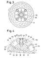
- FIG. 3 is a section taken along the line III-III in FIG. 1 in accordance with the present invention;
- FIG. 4 is a section taken along the line IV-IV in FIG. 1 in accordance with the present invention;
- FIG. 5, 6 and 7 are three view similar to FIG.4, showing various modifications; and
- FIG. 8 is a sectional view, similar to FIG. 1 of the second embodiment of a valve timing control divide in accordance with the present invention;
-
- A valve timing control device in accordance with preferred embodiments of the present invention will be described with reference to the attached drawings.
- FIG. 1 to FIG. 7 show a first embodiment of the present invention. Referring to FIG. 1, a valve timing control device of the first embodiment includes an
exhaust cam shaft 10, asensor plate 20, arotor 30, a plurality ofvanes 40 and ahousing 50. Theexhaust cam shaft 10 is rotatably mounted on acylinder head 80 of an engine E. Theexhaust cam shaft 10 has twocircular grooves circular grooves sensor plate 20 and therotor 30 are fixed to the projecting end of theexhaust cam shaft 10 by abolt 90. Thesensor plate 20 has threeshort projections long projection 24 in the circumferential direction as shown FIG. 2. Thesensor plate 20 has arim 25. Therotor 30 has a plurality of grooves for inserting thevanes 40 as shown in FIG. 4 to FIG. 7. One side end of thehousing 50 is fixed to atiming pulley 70 and the other side end of thehousing 50 is fixed to aside plate 71 by abolt 91. Therefore, thehousing 50, thetiming pulley 70 and theside plate 71 act in a body. Thetiming pulley 70 is transmitted rotational torque via a belt 72 (or a chain 72) from acrank shaft 83 which is rotated by the engineE. A pin 60 is able to connect with between therotor 30 find thehousing 50 when therotor 30 is in phase with thehousing 50. - The
exhaust cam shaft 10 has a plurality of cams (not shown). Each cam makes an exhaust valve open and close. There is apassage 11 which is formed inexhaust cam shaft 10 at its axial centre and extends in the axial direction. One end of thepassage 11 communicates with thecircular groove 14 through apassage 13. Thecircular groove 14 communicates with apassage 81 which is formed in thecylinder head 80 of the engine E. On the other hand, there are a plurality ofpassages 12 which are formed in theexhaust cam shaft 10 and located on a coaxial circle about the axial centre of theshaft 10 and which extend in parallel in the axial direction. One end of thepassages 12 communicates with thecircular groove 15. Thecircular groove 15 communicates with apassage 82 which is formed in thecylinder head 80 of an engine E. Both. thepassages fluid supplying device 100. Thefluid supplying device 100 comprises achangeover valve 101, afluid pump 102 and a.controller 103. In this embodiment, thechangeover valve 101 is a. four port-three position type electromagnetic valve. Thefluid pump 102 is driven by the engine E and discharges the fluid (=oil) for lubricating the engine E. Thepump 102 may be a pump for lubricating the engine E. - The
passage 82 communicates with a port A of thechangeover valve 101 and apassage 81 communicates with a part 8 of thechangeover valve 101. A port P of thechangeover valve 101 communicates with a discharge portion of thefluid pump 102 via apassage 105 and a port R of thechangeover valve 101 communicates with areservoir 104 via apassage 106. The position of thechangeover valve 101 is controlled by thecontroller 103. in a first condition as shown in FIG. 1 the discharged fluid from thepump 102 is supplied to thepassage 82 and thepassage 81 communicates with thereservoir 104, in a second condition all the ports A, B, P, R are interrupted; in a third condition 1 the discharged fluid from thepump 102 is supplied to thepassage 81 and thepassage 82 communicates with the reservoir 104) are selectively obtained. Thecontroller 103 controls the above conditions of thechangeover valve 101 based on parameter signals such as engine speed, the opening level of a throttle valve (not shown) and so on. - In the
rotor 30 and thehousing 50, a valve timing control mechanism V is mounted. Therotor 30 has a cylindrical shape. As shown in FIG. 4 to FIG. 7, thehousing 50 has an inner bore, 54 and is rotatably mounted on the outer circumferential surface of therotor 30 so as to surround therotor 30. Thehousing 50 has the same axial length as therotor 30 and is provided with a plurality ofgrooves 51 which are outwardly extended from theinner bore 54 in the radial direction and which are separated in the circumferential direction at regular intervals Thehousing 50 is also provided with a plurality ofholes 53 for penetration of thebolt 91. Theholes 53 penetrate in the axial direction and are separated in the circumferential direction at regular intervals. - Thereby, a plurality of chambers RO which are separated in the circumferential direction at regular intervals and each of which has a pair of circumferentially opposed
walls rotor 30, thehousing 50, the timingpulley 70 and theside plate 71. On the outer circumferential portion of therotor 30, there are somegrooves 31. The number ofgrooves 31 is equal to the number of chambers RO. Each of thegrooves 31 extends inwardly therefrom in the radial direction. The grooves are located at regular intervals in the circumferential direction. The vanes that extend outwardly in the radial direction into the chambers RO are mounted in thegrooves 31. Thereby, each of the chambers RO is divided into a first pressure chamber R1 and a second pressure chamber R2, both of which are fluidtightly separated from each other. - The
housing 50 has ahole 52 which extends in the radial direction. Thehole 52 is able to accommodate thepin 60 which is pushed towards therotor 30 by a coil-spring 61. The coil-spring 61 is supported by aclip 63 through aretainer 62. On the other hand, therotor 30 on its outer circumferential surface has ahole 32 which extends inwardly thereof in the radial direction so as to accommodate thepin 60. - The
rotor 30 is provided with a plurality offirst passages 34, a plurality ofsecond passages 36, and apassage 35. Thefirst passages 34 and thepassage 35 are in communication. One end of each of thefirst passages 34 communicates with thepassage 11 and the other end of thefirst passages 34 communicates with each of the first chambers R1. On the other hand, one end of each of thesecond passages 36 communicates with thepassage 12 and the other end of the second passages communicates with each of the second chambers R2. - There is a coil-
spring 92. One end of the coil-spring 92 is connected with therotor 30 and the other end of the coil-spring 92 is connected with theside plate 71 which is fixed to thehousing 50. The outer surface of therim 25 of thesensor plate 20 guides the coil portion of the coil-spring 92 as shown in FIG. 1. - The operation of the valve timing control device having the above structure will now be described.
- The
exhaust camshaft 10 is rotated counterclockwise by timingpulley 70. Thereby, exhaust valves (not shown) are opened and closed. - The pressure of the fluid delivered from the
oil pump 102 is increased. Fluid under the resulting pressure is supplied to thechangeover valve 101. At the time, thechangeover valve 101 is in the first condition as shown in FIG. 1, fluid is supplied to the chambers R2 via thepassage 82, thepassage 12 andsecond passages 36. Thereby, thevanes 40 are rotated in the counterclockwise direction, together with therotor 30 and theexhaust cam shaft 10. Upon fitting of thepin 60 into thehole 32 of therotor 30, such rotation is terminated. Thus, thecam shaft 10 is advanced through an angle relative to thecrank shaft 83. - On the other hand, for returning the
exhaust cam shaft 10 from the advanced condition to the retarded condition, thevanes 40 are rotated in the clockwise direction by supplying fluid under pressure to the chambers R1 via thepassage 81, thepassage 11 and thefirst passages 34. Since thefirst passage 34 communicates with thepassage 35, fluid under pressure supplied into thehole 32 urges thepin 60 fully into thehole 52 of thehousing 50 as shown in FIG. 5, thereby releasing the connection between therotor 30 and thehousing 50. With increasing pressure in the chamber R1, thevanes 40 are rotated in the clockwise direction as shown in FIG. 7 via the condition shown in FIG. 6. During the retarding rotary movement of thevanes 40, fluid in each of chambers R2 is drained to thereservoir 104 through thepassage 36, thepassage 12,second passages 82 and thechangeover valve 101. - When the engine E is stopped, the fluid pressure in the chambers R1 and R2 is drained with the elapse of time through a non-illustrated clearance between the parts, for example, between the
exhaust cam shaft 10 and thecylinder head 80. Therefore, the coil-spring urges therotor 30 in the counterclockwise direction so as to fit thepin 60 into thehole 32 of therotor 30. - FIG. 8 illustrates a second embodiment, which specifically is a modified arrangement of a coil-
spring 93. In FIG. 8, corresponding parts to those shown in FIG. 1 are given the same reference numerals. In this modified construction, the coil-spring 93 is arranged within thehousing 50 between therotor 30 and the timingpulley 70. The timingpulley 70 has a cylindrical hollow 74. The cylindrical hollow 74 accommodates the coil-spring 93 which one end thereof is connected with therotor 30 and which the other end thereof is connected with the timingpulley 70 which is fixed to thehousing 50.
Claims (9)
- A valve timing control device comprising:CHARACTERIZED IN THAT a spring element (92,93) is provided within the device to urge the rotor (30) towards the angular position in which it is locked.a rotor (30) fixed on a cam shaft (10) of an engine (E);a housing member (50) rotatably mounted on the cam shaft (10) so as to surround the rotor (30);means (70) for driving the housing member (50) from a rotational output of the engine (E);a chamber (R0) defined between the housing member (50) and the rotor (30) and having a pair of circumferentially opposed walls (55,56);a vane (40) mounted on the rotor (30) and extending outwardly therefrom in the radial direction into the chamber (R0) so as to divide the chamber into a first pressure chamber (R1) and a second pressure chamber (R2);a fluid supplying means (100) for supplying fluid under pressure selectively to one of the first and second pressure chambers (R1 and R2) thereby establishing a pressure differential between said pressure chambers (R1 and R2) so as to effect relative rotation between the rotor (30) and the housing member (50); andmeans (60) for locking the rotor (30) and the housing member (50) in a predetermined relative angular disposition and for selectively releasing that locking engagement;
- A valve timing control device according to claim 1, wherein the spring element (92,93) is a coil-spring (92,93) and one end of the coil-spring is fixed to the rotor (30), and the other end of the coil-spring is fixed to the housing member (50).
- A valve timing control device according to claim 2, wherein the rotor (30) and the housing member (50) are arranged between the coil-spring (92) and the engine.
- A valve timing control device according to claim 3, wherein the coil-spring is guided by a sensor plate (20) which is arranged at the end of the cam shaft (30).
- A valve timing device according to claim 2, wherein the coil spring (92,93) is a torsion spring.
- A valve timing device according to claim 2, wherein the coil spring (92,93) has an axis coincident with the axis of the camshaft (10).
- A valve timing control device according to claim 6, wherein the coil spring (92) is a cylindrically formed coil spring one axial end of which locates in a cylindrical recess in the rotor (30) and is anchored to the rotor, and the other axial end of which locates in a cylindrical space between a member (71) fast to the housing member (50) and a member (25) fast to the rotor (30).
- A valve timing control device accorsing to claim 6, wherein the coil spring (93) is a cylindrically formed coil spring which is located in a cylindrical hollow (74) in the driving means (70).
- A valve timing control according to any preceding claim, wherein the cam shaft (10) controls one or more exhaust valves of the engine (E) and the spring element (92,93) acts to bias the rotor (30) to an advanced valve timing condition.
Priority Applications (2)
| Application Number | Priority Date | Filing Date | Title |
|---|---|---|---|
| EP10010241.7A EP2320037B8 (en) | 1996-03-28 | 1997-03-26 | Camshaft phasing device |
| EP01106890A EP1128028B8 (en) | 1996-03-28 | 1997-03-26 | Valve timing control device |
Applications Claiming Priority (6)
| Application Number | Priority Date | Filing Date | Title |
|---|---|---|---|
| JP7482396 | 1996-03-28 | ||
| JP74823/96 | 1996-03-28 | ||
| JP07482396A JP3365199B2 (en) | 1996-03-28 | 1996-03-28 | Valve timing control device |
| JP6324797A JP3812692B2 (en) | 1997-03-17 | 1997-03-17 | Valve timing control device |
| JP6324797 | 1997-03-17 | ||
| JP63247/97 | 1997-03-17 |
Related Child Applications (1)
| Application Number | Title | Priority Date | Filing Date |
|---|---|---|---|
| EP01106890A Division EP1128028B8 (en) | 1996-03-28 | 1997-03-26 | Valve timing control device |
Publications (3)
| Publication Number | Publication Date |
|---|---|
| EP0806550A1 EP0806550A1 (en) | 1997-11-12 |
| EP0806550B1 true EP0806550B1 (en) | 2001-12-19 |
| EP0806550B2 EP0806550B2 (en) | 2008-08-20 |
Family
ID=26404328
Family Applications (3)
| Application Number | Title | Priority Date | Filing Date |
|---|---|---|---|
| EP97302104A Expired - Lifetime EP0806550B2 (en) | 1996-03-28 | 1997-03-26 | Valve timing control device |
| EP01106890A Expired - Lifetime EP1128028B8 (en) | 1996-03-28 | 1997-03-26 | Valve timing control device |
| EP10010241.7A Expired - Lifetime EP2320037B8 (en) | 1996-03-28 | 1997-03-26 | Camshaft phasing device |
Family Applications After (2)
| Application Number | Title | Priority Date | Filing Date |
|---|---|---|---|
| EP01106890A Expired - Lifetime EP1128028B8 (en) | 1996-03-28 | 1997-03-26 | Valve timing control device |
| EP10010241.7A Expired - Lifetime EP2320037B8 (en) | 1996-03-28 | 1997-03-26 | Camshaft phasing device |
Country Status (3)
| Country | Link |
|---|---|
| US (1) | US5775279A (en) |
| EP (3) | EP0806550B2 (en) |
| DE (1) | DE69709231T3 (en) |
Cited By (4)
| Publication number | Priority date | Publication date | Assignee | Title |
|---|---|---|---|---|
| DE102006022219A1 (en) * | 2006-05-11 | 2007-11-22 | Hydraulik-Ring Gmbh | Leakage-proof camshaft adjuster with return spring |
| DE102007020524A1 (en) | 2007-05-02 | 2008-11-06 | Schaeffler Kg | Camshaft setter, for an internal combustion motor, has a starting disk as a trigger wheel with a flat body and a bar geometry to sense the camshaft phase |
| DE102008017688A1 (en) | 2008-04-08 | 2009-10-15 | Schaeffler Kg | Device for the variable adjustment of the timing of gas exchange valves of an internal combustion engine |
| DE102010013928A1 (en) | 2010-04-06 | 2011-10-06 | Schaeffler Technologies Gmbh & Co. Kg | Rotor assembly for cam shaft adjuster of cam shaft adjustable system, has short axial channel connected with oil distribution chamber between inner circumference of hub part and central screw, where channel is connected with one of channels |
Families Citing this family (52)
| Publication number | Priority date | Publication date | Assignee | Title |
|---|---|---|---|---|
| JP3116858B2 (en) * | 1996-11-29 | 2000-12-11 | トヨタ自動車株式会社 | Variable valve timing mechanism for internal combustion engine |
| US6158404A (en) | 1997-02-26 | 2000-12-12 | Aft Atlas Fahrzeugtechnik Gmbh | Apparatus for regulating the operation of an adjusting device |
| DE19716203A1 (en) * | 1997-04-18 | 1998-10-22 | Schaeffler Waelzlager Ohg | Mechanism for varying opening and closing times of internal combustion engine gas shuttle valves |
| JP3760566B2 (en) * | 1997-06-05 | 2006-03-29 | アイシン精機株式会社 | Valve timing control device |
| JP3760568B2 (en) * | 1997-06-05 | 2006-03-29 | アイシン精機株式会社 | Valve timing control device |
| DE19723945A1 (en) * | 1997-06-06 | 1998-12-10 | Schaeffler Waelzlager Ohg | Gas exchange valve timing gear for IC engine |
| DE19724989A1 (en) * | 1997-06-13 | 1998-12-17 | Schaeffler Waelzlager Ohg | Control time adjusting device for internal combustion engine |
| JP3824110B2 (en) * | 1997-06-30 | 2006-09-20 | アイシン精機株式会社 | Valve timing control device |
| JP3801747B2 (en) * | 1997-09-29 | 2006-07-26 | アイシン精機株式会社 | Valve timing control device |
| JP3846605B2 (en) * | 1997-10-30 | 2006-11-15 | アイシン精機株式会社 | Valve timing control device |
| DE19854891C2 (en) * | 1997-11-28 | 2003-02-06 | Aisin Seiki | Valve timing control device |
| DE19755495A1 (en) * | 1997-12-13 | 1999-06-17 | Schaeffler Waelzlager Ohg | Arrangement for controlling the air/fuel ratio in an internal combustion engine |
| DE19756017A1 (en) * | 1997-12-17 | 1999-06-24 | Porsche Ag | Device for changing the relative rotational position of a shaft to the drive wheel |
| JP3815014B2 (en) * | 1997-12-24 | 2006-08-30 | アイシン精機株式会社 | Valve timing control device |
| JP4147435B2 (en) * | 1998-01-30 | 2008-09-10 | アイシン精機株式会社 | Valve timing control device |
| US5924407A (en) * | 1998-07-29 | 1999-07-20 | Navistar International Transportation Corp. | Commanded, rail-pressure-based, variable injector boost current duration |
| US6311654B1 (en) | 1998-07-29 | 2001-11-06 | Denso Corporation | Valve timing adjusting device |
| JP4158185B2 (en) | 1999-12-15 | 2008-10-01 | 株式会社デンソー | Valve timing adjustment device |
| US6412462B1 (en) | 2000-01-18 | 2002-07-02 | Delphi Technologies, Inc. | Cam phaser apparatus having a stator integral with a back plate or a front cover plate |
| DE10103876B4 (en) * | 2000-01-31 | 2005-12-01 | Aisin Seiki K.K., Kariya | Valve timing adjustment device for internal combustion engines |
| DE10007200A1 (en) * | 2000-02-17 | 2001-08-23 | Schaeffler Waelzlager Ohg | Device for changing the control times of gas exchange valves of an internal combustion engine |
| JP4240756B2 (en) * | 2000-05-10 | 2009-03-18 | アイシン精機株式会社 | Valve timing control device |
| JP4032288B2 (en) * | 2002-03-28 | 2008-01-16 | アイシン精機株式会社 | Valve timing control device |
| US6871620B2 (en) * | 2002-04-09 | 2005-03-29 | Ford Global Technologies, Llc | Variable cam timing unit oil supply arrangement |
| DE102004028869A1 (en) * | 2004-06-15 | 2006-01-05 | Ina-Schaeffler Kg | Hydraulic apparatus for controlling camshaft to crankshaft rotation angle includes using a rotor having torque proof vanes attached in cavities in the rotor |
| US7305949B2 (en) * | 2005-08-18 | 2007-12-11 | Delphi Technologies, Inc. | Stamped target wheel for a camshaft phaser |
| DE102005060111A1 (en) * | 2005-12-16 | 2007-07-05 | Schaeffler Kg | Camshaft adjuster feed line |
| DE102007041552A1 (en) | 2007-08-31 | 2009-03-05 | Schaeffler Kg | Device for the variable adjustment of the timing of gas exchange valves of an internal combustion engine |
| DE102007056685A1 (en) * | 2007-11-24 | 2009-05-28 | Schaeffler Kg | Device for the variable adjustment of the timing of gas exchange valves of an internal combustion engine |
| DE102007056683A1 (en) | 2007-11-24 | 2009-05-28 | Schaeffler Kg | Device for the variable adjustment of the timing of gas exchange valves of an internal combustion engine |
| JP4851475B2 (en) | 2008-02-08 | 2012-01-11 | 株式会社デンソー | Valve timing adjustment device |
| DE102008017455A1 (en) | 2008-04-05 | 2009-10-08 | Schaeffler Kg | Camshaft adjustment device |
| DE102008037996A1 (en) | 2008-08-16 | 2010-02-18 | Schaeffler Kg | Device for variably adjusting control time of inlet gas shuttle valve and outlet gas shuttle valve of internal-combustion engine, has separation element with two porous sections that limit respective chamber in shifting direction of element |
| DE102008037997B4 (en) | 2008-08-16 | 2019-08-22 | Schaeffler Technologies AG & Co. KG | Device for the variable adjustment of the timing of gas exchange valves of an internal combustion engine |
| DE102009034011B4 (en) | 2008-10-07 | 2018-04-05 | Schaeffler Technologies AG & Co. KG | Pressure accumulator to support the pressure medium supply of a camshaft adjuster an internal combustion engine |
| DE102009016186A1 (en) | 2009-04-03 | 2010-10-14 | Schaeffler Technologies Gmbh & Co. Kg | Apparatus for variably adjusting timing of inlet and outlet gas exchange valves of internal combustion engine, has opening communicating with pressurizing medium line that is formed in cylinder head fixed component and opens into receptacle |
| DE102009030201A1 (en) | 2009-06-24 | 2010-12-30 | Schaeffler Technologies Gmbh & Co. Kg | Device for the variable adjustment of the timing of gas exchange valves of an internal combustion engine |
| DE102009042202A1 (en) | 2009-09-18 | 2011-04-14 | Schaeffler Technologies Gmbh & Co. Kg | Device for the variable adjustment of the timing of gas exchange valves of an internal combustion engine |
| DE102009049461A1 (en) | 2009-10-15 | 2011-04-21 | Schaeffler Technologies Gmbh & Co. Kg | volume storage |
| DE102009049459A1 (en) | 2009-10-15 | 2011-04-21 | Schaeffler Technologies Gmbh & Co. Kg | volume storage |
| DE102009056021A1 (en) | 2009-11-27 | 2011-06-01 | Schaeffler Technologies Gmbh & Co. Kg | Device for variably setting the control times of gas exchange valves of an internal combustion engine |
| DE102009056020A1 (en) | 2009-11-27 | 2011-06-01 | Schaeffler Technologies Gmbh & Co. Kg | Device for the variable adjustment of the timing of gas exchange valves of an internal combustion engine |
| DE102009056018A1 (en) | 2009-11-27 | 2011-07-07 | Schaeffler Technologies GmbH & Co. KG, 91074 | Device for the variable adjustment of the timing of gas exchange valves of an internal combustion engine |
| DE102009056024A1 (en) | 2009-11-27 | 2011-06-01 | Schaeffler Technologies Gmbh & Co. Kg | Camshaft adjuster for camshaft, has pressure chamber and adjusting unit arranged in pressure chamber, where adjusting unit divides pressure chamber into two partial chambers |
| DE102009056023A1 (en) | 2009-11-27 | 2011-06-01 | Schaeffler Technologies Gmbh & Co. Kg | Camshaft adjuster for camshaft, has valve housing with openings communicating with partial chamber and other openings communicating with another partial chamber |
| JP5505257B2 (en) * | 2010-10-27 | 2014-05-28 | アイシン精機株式会社 | Valve timing control device |
| DE102011003991A1 (en) | 2011-02-11 | 2012-08-16 | Schaeffler Technologies Gmbh & Co. Kg | Camshaft adjuster with a pressure accumulator |
| DE102011004539A1 (en) * | 2011-02-22 | 2012-08-23 | Schwäbische Hüttenwerke Automotive GmbH | Camshaft phaser with improved locking device |
| DE102011007883A1 (en) * | 2011-04-21 | 2012-10-25 | Schaeffler Technologies AG & Co. KG | Phaser |
| DE102012008609A1 (en) | 2012-04-27 | 2013-10-31 | Volkswagen Aktiengesellschaft | Camshaft adjustment device for camshaft in internal combustion engine, has clamp assembly that is formed between shafts and between drive elements with help of torsion element that is fixed to rotor |
| DE102013219075B4 (en) | 2013-09-23 | 2020-11-26 | Schaeffler Technologies AG & Co. KG | Multi-locking of a camshaft adjuster |
| DE102013220322B4 (en) * | 2013-10-09 | 2020-11-26 | Schaeffler Technologies AG & Co. KG | Camshaft adjustment device |
Family Cites Families (13)
| Publication number | Priority date | Publication date | Assignee | Title |
|---|---|---|---|---|
| JPS5339938B2 (en) * | 1973-10-05 | 1978-10-24 | ||
| DE3616234A1 (en) * | 1986-05-14 | 1987-11-19 | Bayerische Motoren Werke Ag | DEVICE FOR THE RELATIVE TURNING CHANGE OF TWO DRIVELY CONNECTED SHAFTS, ESPECIALLY BETWEEN A CRANKSHAFT AND CAMSHAFT BEARING IN A MACHINE HOUSING OF AN INTERNAL COMBUSTION ENGINE |
| JPH0192504A (en) | 1987-09-30 | 1989-04-11 | Aisin Seiki Co Ltd | Valve opening and closing timing control device |
| DE3810804A1 (en) † | 1988-03-30 | 1989-10-19 | Daimler Benz Ag | DEVICE FOR RELATIVE ANGLE ADJUSTMENT BETWEEN TWO DRIVES CONNECTED |
| DE3825074C1 (en) * | 1988-07-23 | 1989-10-19 | Daimler-Benz Aktiengesellschaft, 7000 Stuttgart, De | |
| DE3907077A1 (en) † | 1989-03-04 | 1990-09-06 | Daimler Benz Ag | DEVICE FOR RELATIVE ANGLE ADJUSTMENT OF A CAMSHAFT OF INTERNAL COMBUSTION ENGINES |
| DE3922962A1 (en) * | 1989-07-12 | 1991-01-17 | Audi Ag | DRIVE DEVICE FOR A CAMSHAFT OF AN INTERNAL COMBUSTION ENGINE |
| DE3930157A1 (en) * | 1989-09-09 | 1991-03-21 | Bosch Gmbh Robert | DEVICE FOR ADJUSTING THE TURNING ANGLE ASSIGNMENT OF A CAMSHAFT TO YOUR DRIVE ELEMENT |
| US5046460A (en) * | 1989-10-16 | 1991-09-10 | Borg-Warner Automotive Transmission & Engine Components Corporation | Variable camshaft timing for internal combustion engine |
| JP3076390B2 (en) * | 1991-03-26 | 2000-08-14 | マツダ株式会社 | Engine cam timing controller |
| DE4218081A1 (en) † | 1992-06-01 | 1993-12-02 | Schaeffler Waelzlager Kg | Displaceable divided piston for changing rotary position of shaft in engine - has support part and end piece each with prefab. inclined gearing sections to form gearing pairs with adjoining components |
| IT1271511B (en) † | 1993-10-06 | 1997-05-30 | Carraro Spa | PHASE VARIATOR BETWEEN THE CRANKSHAFT AND THE CAMSHAFT OF AN INTERNAL COMBUSTION ENGINE |
| US5666914A (en) * | 1994-05-13 | 1997-09-16 | Nippondenso Co., Ltd. | Vane type angular phase adjusting device |
-
1997
- 1997-03-26 EP EP97302104A patent/EP0806550B2/en not_active Expired - Lifetime
- 1997-03-26 DE DE69709231T patent/DE69709231T3/en not_active Expired - Lifetime
- 1997-03-26 EP EP01106890A patent/EP1128028B8/en not_active Expired - Lifetime
- 1997-03-26 EP EP10010241.7A patent/EP2320037B8/en not_active Expired - Lifetime
- 1997-03-28 US US08/828,937 patent/US5775279A/en not_active Expired - Lifetime
Cited By (5)
| Publication number | Priority date | Publication date | Assignee | Title |
|---|---|---|---|---|
| DE102006022219A1 (en) * | 2006-05-11 | 2007-11-22 | Hydraulik-Ring Gmbh | Leakage-proof camshaft adjuster with return spring |
| DE102006022219B4 (en) * | 2006-05-11 | 2008-01-03 | Hydraulik-Ring Gmbh | Leakage-proof camshaft adjuster with return spring |
| DE102007020524A1 (en) | 2007-05-02 | 2008-11-06 | Schaeffler Kg | Camshaft setter, for an internal combustion motor, has a starting disk as a trigger wheel with a flat body and a bar geometry to sense the camshaft phase |
| DE102008017688A1 (en) | 2008-04-08 | 2009-10-15 | Schaeffler Kg | Device for the variable adjustment of the timing of gas exchange valves of an internal combustion engine |
| DE102010013928A1 (en) | 2010-04-06 | 2011-10-06 | Schaeffler Technologies Gmbh & Co. Kg | Rotor assembly for cam shaft adjuster of cam shaft adjustable system, has short axial channel connected with oil distribution chamber between inner circumference of hub part and central screw, where channel is connected with one of channels |
Also Published As
| Publication number | Publication date |
|---|---|
| EP1128028B8 (en) | 2012-11-07 |
| US5775279A (en) | 1998-07-07 |
| EP0806550A1 (en) | 1997-11-12 |
| DE69709231T2 (en) | 2002-08-08 |
| EP1128028A3 (en) | 2003-02-19 |
| EP0806550B2 (en) | 2008-08-20 |
| EP2320037B1 (en) | 2013-07-24 |
| EP1128028A2 (en) | 2001-08-29 |
| EP2320037B8 (en) | 2013-11-13 |
| EP1128028B1 (en) | 2012-01-25 |
| DE69709231T3 (en) | 2009-01-08 |
| DE69709231D1 (en) | 2002-01-31 |
| EP2320037A1 (en) | 2011-05-11 |
Similar Documents
| Publication | Publication Date | Title |
|---|---|---|
| EP0806550B1 (en) | Valve timing control device | |
| US5836275A (en) | Valve timing control device | |
| KR100242589B1 (en) | Variable valve timing mechanism of internal combustion engine | |
| EP0937865B1 (en) | Variable valve timing apparatus | |
| EP1229216B1 (en) | Valve timing control device | |
| US20020017255A1 (en) | Variable valve timing system | |
| EP0821138B1 (en) | Valve timing control devices | |
| US6105543A (en) | Valve timing control device | |
| EP0818610B1 (en) | Valve timing control devices | |
| US6062182A (en) | Valve timing control device | |
| US6334414B1 (en) | Valve timing adjusting apparatus | |
| EP0781899B1 (en) | Valve timing control device | |
| JPH1113432A (en) | Valve timing control device | |
| JP2001090512A (en) | Valve timing control device | |
| JP3845986B2 (en) | Valve timing control device | |
| JPH09250310A (en) | Valve timing changing device for internal combustion engine | |
| JP4016527B2 (en) | Valve timing control device | |
| JP3744666B2 (en) | Valve timing control device | |
| JP3081191B2 (en) | Hydraulic valve timing adjustment device | |
| JP4538937B2 (en) | Valve timing control device | |
| JPH10159515A (en) | Valve timing control device for internal combustion engine | |
| JP3873466B2 (en) | Valve timing control device | |
| JP4026286B2 (en) | Valve timing control device | |
| JP3058096B2 (en) | Variable valve timing device for internal combustion engine | |
| JPH10252420A (en) | Valve timing control device |
Legal Events
| Date | Code | Title | Description |
|---|---|---|---|
| PUAI | Public reference made under article 153(3) epc to a published international application that has entered the european phase |
Free format text: ORIGINAL CODE: 0009012 |
|
| AK | Designated contracting states |
Kind code of ref document: A1 Designated state(s): DE FR GB IT |
|
| 17P | Request for examination filed |
Effective date: 19971122 |
|
| 17Q | First examination report despatched |
Effective date: 19980624 |
|
| GRAG | Despatch of communication of intention to grant |
Free format text: ORIGINAL CODE: EPIDOS AGRA |
|
| GRAG | Despatch of communication of intention to grant |
Free format text: ORIGINAL CODE: EPIDOS AGRA |
|
| GRAG | Despatch of communication of intention to grant |
Free format text: ORIGINAL CODE: EPIDOS AGRA |
|
| GRAH | Despatch of communication of intention to grant a patent |
Free format text: ORIGINAL CODE: EPIDOS IGRA |
|
| GRAH | Despatch of communication of intention to grant a patent |
Free format text: ORIGINAL CODE: EPIDOS IGRA |
|
| GRAA | (expected) grant |
Free format text: ORIGINAL CODE: 0009210 |
|
| AK | Designated contracting states |
Kind code of ref document: B1 Designated state(s): DE FR GB IT |
|
| PG25 | Lapsed in a contracting state [announced via postgrant information from national office to epo] |
Ref country code: IT Free format text: LAPSE BECAUSE OF FAILURE TO SUBMIT A TRANSLATION OF THE DESCRIPTION OR TO PAY THE FEE WITHIN THE PRESCRIBED TIME-LIMIT;WARNING: LAPSES OF ITALIAN PATENTS WITH EFFECTIVE DATE BEFORE 2007 MAY HAVE OCCURRED AT ANY TIME BEFORE 2007. THE CORRECT EFFECTIVE DATE MAY BE DIFFERENT FROM THE ONE RECORDED. Effective date: 20011219 |
|
| REG | Reference to a national code |
Ref country code: GB Ref legal event code: IF02 |
|
| REF | Corresponds to: |
Ref document number: 69709231 Country of ref document: DE Date of ref document: 20020131 |
|
| ET | Fr: translation filed | ||
| PLBI | Opposition filed |
Free format text: ORIGINAL CODE: 0009260 |
|
| PLBQ | Unpublished change to opponent data |
Free format text: ORIGINAL CODE: EPIDOS OPPO |
|
| PLAB | Opposition data, opponent's data or that of the opponent's representative modified |
Free format text: ORIGINAL CODE: 0009299OPPO |
|
| PLBI | Opposition filed |
Free format text: ORIGINAL CODE: 0009260 |
|
| 26 | Opposition filed |
Opponent name: INA-SCHAEFFLER KG Effective date: 20020820 |
|
| R26 | Opposition filed (corrected) |
Opponent name: INA-SCHAEFFLER KG * 20020913 DAIMLERCHRYSLER AG IN Effective date: 20020820 |
|
| PLBF | Reply of patent proprietor to notice(s) of opposition |
Free format text: ORIGINAL CODE: EPIDOS OBSO |
|
| PLBF | Reply of patent proprietor to notice(s) of opposition |
Free format text: ORIGINAL CODE: EPIDOS OBSO |
|
| PLBF | Reply of patent proprietor to notice(s) of opposition |
Free format text: ORIGINAL CODE: EPIDOS OBSO |
|
| PLBQ | Unpublished change to opponent data |
Free format text: ORIGINAL CODE: EPIDOS OPPO |
|
| PLAB | Opposition data, opponent's data or that of the opponent's representative modified |
Free format text: ORIGINAL CODE: 0009299OPPO |
|
| R26 | Opposition filed (corrected) |
Opponent name: DAIMLERCHRYSLER AGINTELLECTUAL PROPERTY MANAGEMENT Effective date: 20020913 Opponent name: INA-SCHAEFFLER KG Effective date: 20020820 |
|
| APAY | Date of receipt of notice of appeal deleted |
Free format text: ORIGINAL CODE: EPIDOSDNOA2O |
|
| APBP | Date of receipt of notice of appeal recorded |
Free format text: ORIGINAL CODE: EPIDOSNNOA2O |
|
| APAY | Date of receipt of notice of appeal deleted |
Free format text: ORIGINAL CODE: EPIDOSDNOA2O |
|
| APBP | Date of receipt of notice of appeal recorded |
Free format text: ORIGINAL CODE: EPIDOSNNOA2O |
|
| APBP | Date of receipt of notice of appeal recorded |
Free format text: ORIGINAL CODE: EPIDOSNNOA2O |
|
| APBQ | Date of receipt of statement of grounds of appeal recorded |
Free format text: ORIGINAL CODE: EPIDOSNNOA3O |
|
| APBQ | Date of receipt of statement of grounds of appeal recorded |
Free format text: ORIGINAL CODE: EPIDOSNNOA3O |
|
| APAA | Appeal reference recorded |
Free format text: ORIGINAL CODE: EPIDOS REFN |
|
| APAH | Appeal reference modified |
Free format text: ORIGINAL CODE: EPIDOSCREFNO |
|
| PLAB | Opposition data, opponent's data or that of the opponent's representative modified |
Free format text: ORIGINAL CODE: 0009299OPPO |
|
| R26 | Opposition filed (corrected) |
Opponent name: DAIMLERCHRYSLER AG I Effective date: 20020913 Opponent name: SCHAEFFLER KG Effective date: 20020820 |
|
| APBU | Appeal procedure closed |
Free format text: ORIGINAL CODE: EPIDOSNNOA9O |
|
| APBW | Interlocutory revision of appeal recorded |
Free format text: ORIGINAL CODE: EPIDOSNIRAPO |
|
| APAH | Appeal reference modified |
Free format text: ORIGINAL CODE: EPIDOSCREFNO |
|
| APBP | Date of receipt of notice of appeal recorded |
Free format text: ORIGINAL CODE: EPIDOSNNOA2O |
|
| APBU | Appeal procedure closed |
Free format text: ORIGINAL CODE: EPIDOSNNOA9O |
|
| PUAH | Patent maintained in amended form |
Free format text: ORIGINAL CODE: 0009272 |
|
| STAA | Information on the status of an ep patent application or granted ep patent |
Free format text: STATUS: PATENT MAINTAINED AS AMENDED |
|
| 27A | Patent maintained in amended form |
Effective date: 20080820 |
|
| AK | Designated contracting states |
Kind code of ref document: B2 Designated state(s): DE FR GB IT |
|
| REG | Reference to a national code |
Ref country code: FR Ref legal event code: PLFP Year of fee payment: 20 |
|
| PGFP | Annual fee paid to national office [announced via postgrant information from national office to epo] |
Ref country code: DE Payment date: 20160322 Year of fee payment: 20 |
|
| PGFP | Annual fee paid to national office [announced via postgrant information from national office to epo] |
Ref country code: FR Payment date: 20160208 Year of fee payment: 20 Ref country code: GB Payment date: 20160323 Year of fee payment: 20 |
|
| REG | Reference to a national code |
Ref country code: DE Ref legal event code: R071 Ref document number: 69709231 Country of ref document: DE |
|
| REG | Reference to a national code |
Ref country code: GB Ref legal event code: PE20 Expiry date: 20170325 |
|
| PG25 | Lapsed in a contracting state [announced via postgrant information from national office to epo] |
Ref country code: GB Free format text: LAPSE BECAUSE OF EXPIRATION OF PROTECTION Effective date: 20170325 |