EP0806503B1 - A doubled yarn false twisting machine - Google Patents
A doubled yarn false twisting machine Download PDFInfo
- Publication number
- EP0806503B1 EP0806503B1 EP19970105860 EP97105860A EP0806503B1 EP 0806503 B1 EP0806503 B1 EP 0806503B1 EP 19970105860 EP19970105860 EP 19970105860 EP 97105860 A EP97105860 A EP 97105860A EP 0806503 B1 EP0806503 B1 EP 0806503B1
- Authority
- EP
- European Patent Office
- Prior art keywords
- yarn
- untwisting tension
- tension
- untwisting
- twisting machine
- Prior art date
- Legal status (The legal status is an assumption and is not a legal conclusion. Google has not performed a legal analysis and makes no representation as to the accuracy of the status listed.)
- Expired - Lifetime
Links
- 241001589086 Bellapiscis medius Species 0.000 claims description 18
- 230000007423 decrease Effects 0.000 claims description 6
- 238000001514 detection method Methods 0.000 description 48
- 235000004879 dioscorea Nutrition 0.000 description 9
- 238000004804 winding Methods 0.000 description 8
- 230000008859 change Effects 0.000 description 7
- 238000011144 upstream manufacturing Methods 0.000 description 6
- 238000001816 cooling Methods 0.000 description 5
- 238000000034 method Methods 0.000 description 5
- 230000008569 process Effects 0.000 description 5
- 238000007726 management method Methods 0.000 description 3
- 239000002216 antistatic agent Substances 0.000 description 2
- 238000004519 manufacturing process Methods 0.000 description 2
- 230000008685 targeting Effects 0.000 description 2
- 230000002950 deficient Effects 0.000 description 1
- 230000005611 electricity Effects 0.000 description 1
- 239000000835 fiber Substances 0.000 description 1
- 239000012530 fluid Substances 0.000 description 1
- 239000000314 lubricant Substances 0.000 description 1
- 230000037361 pathway Effects 0.000 description 1
- 230000004044 response Effects 0.000 description 1
- 230000003068 static effect Effects 0.000 description 1
Images


Classifications
-
- D—TEXTILES; PAPER
- D02—YARNS; MECHANICAL FINISHING OF YARNS OR ROPES; WARPING OR BEAMING
- D02G—CRIMPING OR CURLING FIBRES, FILAMENTS, THREADS, OR YARNS; YARNS OR THREADS
- D02G1/00—Producing crimped or curled fibres, filaments, yarns, or threads, giving them latent characteristics
- D02G1/02—Producing crimped or curled fibres, filaments, yarns, or threads, giving them latent characteristics by twisting, fixing the twist and backtwisting, i.e. by imparting false twist
- D02G1/04—Devices for imparting false twist
-
- B—PERFORMING OPERATIONS; TRANSPORTING
- B65—CONVEYING; PACKING; STORING; HANDLING THIN OR FILAMENTARY MATERIAL
- B65H—HANDLING THIN OR FILAMENTARY MATERIAL, e.g. SHEETS, WEBS, CABLES
- B65H54/00—Winding, coiling, or depositing filamentary material
- B65H54/02—Winding and traversing material on to reels, bobbins, tubes, or like package cores or formers
- B65H54/026—Doubling winders, i.e. for winding two or more parallel yarns on a bobbin, e.g. in preparation for twisting or weaving
-
- B—PERFORMING OPERATIONS; TRANSPORTING
- B65—CONVEYING; PACKING; STORING; HANDLING THIN OR FILAMENTARY MATERIAL
- B65H—HANDLING THIN OR FILAMENTARY MATERIAL, e.g. SHEETS, WEBS, CABLES
- B65H63/00—Warning or safety devices, e.g. automatic fault detectors, stop-motions ; Quality control of the package
- B65H63/02—Warning or safety devices, e.g. automatic fault detectors, stop-motions ; Quality control of the package responsive to reduction in material tension, failure of supply, or breakage, of material
-
- D—TEXTILES; PAPER
- D01—NATURAL OR MAN-MADE THREADS OR FIBRES; SPINNING
- D01H—SPINNING OR TWISTING
- D01H1/00—Spinning or twisting machines in which the product is wound-up continuously
- D01H1/11—Spinning by false-twisting
-
- D—TEXTILES; PAPER
- D01—NATURAL OR MAN-MADE THREADS OR FIBRES; SPINNING
- D01H—SPINNING OR TWISTING
- D01H13/00—Other common constructional features, details or accessories
- D01H13/14—Warning or safety devices, e.g. automatic fault detectors, stop motions ; Monitoring the entanglement of slivers in drafting arrangements
- D01H13/16—Warning or safety devices, e.g. automatic fault detectors, stop motions ; Monitoring the entanglement of slivers in drafting arrangements responsive to reduction in material tension, failure of supply, or breakage, of material
-
- D—TEXTILES; PAPER
- D02—YARNS; MECHANICAL FINISHING OF YARNS OR ROPES; WARPING OR BEAMING
- D02G—CRIMPING OR CURLING FIBRES, FILAMENTS, THREADS, OR YARNS; YARNS OR THREADS
- D02G1/00—Producing crimped or curled fibres, filaments, yarns, or threads, giving them latent characteristics
- D02G1/02—Producing crimped or curled fibres, filaments, yarns, or threads, giving them latent characteristics by twisting, fixing the twist and backtwisting, i.e. by imparting false twist
- D02G1/0206—Producing crimped or curled fibres, filaments, yarns, or threads, giving them latent characteristics by twisting, fixing the twist and backtwisting, i.e. by imparting false twist by false-twisting
- D02G1/0266—Producing crimped or curled fibres, filaments, yarns, or threads, giving them latent characteristics by twisting, fixing the twist and backtwisting, i.e. by imparting false twist by false-twisting false-twisting machines
-
- B—PERFORMING OPERATIONS; TRANSPORTING
- B65—CONVEYING; PACKING; STORING; HANDLING THIN OR FILAMENTARY MATERIAL
- B65H—HANDLING THIN OR FILAMENTARY MATERIAL, e.g. SHEETS, WEBS, CABLES
- B65H2701/00—Handled material; Storage means
- B65H2701/30—Handled filamentary material
- B65H2701/31—Textiles threads or artificial strands of filaments
Definitions
- the present invention relates to a doubled yarn false twisting machine.
- a mechanical yarn breakage detection device is also arranged upstream of the first feed rollers that are upstream of where the yarns are combined and does not influence the transfer of the false twist. A breakage in any single yarn may thus be detected before the yarns are combined.
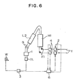
- FIG. 6 A schematic drawing of a conventional doubled gain false twisting machine is shown in Figure 6 with a mechanical yarn breakage detection device 4 being arranged between a cutter 2 and a first feed roller F1.
- the untwisting tension detection device is used to keep the tension within a defined operating range and to maintain a predetermine quality level.
- a mechanical type and electrical capacitance type of yarn breakage detection devices are used on conventional false twisting machines and an antistatic agent is used on partially draw textured yarn being the supply yarn. Detection of the presence or absence of yarn by the electrical capacitance yarn breakage detection device which detects whether there is a yarn by the capacitance of static electricity is very difficult as the yarn is almost completely uncharged and thus a mechanical yarn breakage detection device is used which detects the presence or absence of yarn by contact. This antistatic agent soon becomes ineffective if heated and thus a non-contact electrical capacitance yarn breakage detection device is used for the yarn which has passed through the primary heater.
- the yarn end of the downstream side of the broken yarn may be wound on the winding package or the upstream side yarn end is not wound and becomes entangled on the rotating part of the shaft etc. of the feed roller. If this entanglement occurs, the yarn continues to be fed and forms a lump but even in this case, it is not detected by the yarn breakage detection device. In the worst possible case, this may cause the stoppage of the machine and thus require an operation to remove the entangled lump. As a result, it is preferable to arrange the yarn breakage detection device as far as possible downstream being the winding device side.
- an electrical capacitance or mechanical yarn breakage detection device is not suitable for the detection of a yarn breakage after the doubling of the yarn.
- a high performance device that is able to detect a single yarn breakage whilst in the doubled yarn state has been proposed as an electrical capacitance yarn breakage detection device but this is unusable due to the high costs.
- This problem is accomplished by the features of claim 1.
- This solution is based on the use of the untwisting tension detecting device to detect a single yarn breakage and to cut all yarn forming the doubled yarn.
- the tension detection device for detecting the untwisting tension is connected to the control device that operates the cutter upon judging a yarn breakage from a tension change.
- the cutter is operated due to supposition of a yarn breakage.
- the tension value at which the cutter operates is the value close to zero referring to the margin of error with the zero point setting in the case of tension zero or is the value lower than the aforementioned range of untwisting tension.
- the aforementioned tension detection device measures the combining force of the untwisting tension of the plurality of yarns which are doubled, defines the operating range and judges a yarn breakage when the untwisting tension drops outside of that range.
- the untwisting tension of the conjugated yarn is the sum of the untwisting tensions of each yarn comprising the conjugated yarn
- the tension changes by the amount of the untwisting tension of that broken yarn.
- the untwisting tension is normally always changing to some degree, the change when a single yarn of the yarns comprising the conjugated yarn breaks may not necessarily be due to the untwisting tension of a broken yarn.
- an operating range is defined and the cutter is operated regardless of the presence or absence of yarn when the untwisting tension drops out of that range.
- Single yarn processing may be of course also performed on the doubled yarn false twisting machine if the cutter is disengaged.
- Figure 1 is a schematic drawing of a doubled yarn false twisting machine of the present invention.
- Figure 2 is a side view of the doubled yarn false twisting machine of the present invention.
- Figure 3 and 4 are schematic drawings of untwisting tension detection devices of a false twisting machine.
- Figure 5 is a graph showing the relationship between the untwisting tension and yarn breakage.
- Figure 6 is a schematic drawing of a conventional doubled yarn false twisting machine.
- a draw texturizing machine M being a typical example of the present invention which carries out texture processing of a melt-spun synthetic filament yarn is shown in Figure 2.
- Ps is a supply package that is supported by a creel stand S.
- L1 is a guide pipe that guides a filament yarn Y unwound from supply packages Ps to a first feed roller F1.
- H1 is a primary heater that heat processes the yarn Y false twisted by a false twister 9.
- L2 is a cooling plate that fixes the properties of the yarn heat processed by the primary heater H1 by cooling.
- IL is an entangling device which entangles the yarn Y comprising a plurality of fiber bundles in approximately uniform intervals by a fluid and is able to form conjugated yarn by entangling a plurality of single yarns. Furthermore, when the entangling process is carried out, the unwinding properties are improved in the case of conjugated yarn or single yarn.
- 0 is an oiling roller that applies a lubricant to the yarn Y.
- W is a winding device that winds the yarn Y on a package Pw.
- the draw texturizing machine M is arranged with the creel stand S along the frame K and the filament yarn Y of the supply packages Ps supported on this creel stand S is unwound and guided to the first feed roller F1 by the guide pipe L1.
- a cutter 2 is arranged at the yarn exit hole of this guide pipe L1.
- the yarn is then guided to a second feed roller F2 via the primary heater H1 for texturing, the cooling plate L2, the false twister 9 and an untwisting tension detection device 1 that is arranged in order to obtain various information necessary for quality management of the package such as changes in untwisting tension T.
- the filament yarn Y is false twisted and heat fixed while being draw textured and bulkiness process is imparted on the filament yarn Y.
- the entangling device IL it is wound on the package Pw by the winding device W via a third feed roller F3, a fourth feed roller F4, yam breakage detection device 3, operation alley L3 and oiling roller 0.
- 3 is the yarn breakage detection device which operates the cutter 2 and cuts the yam Y upon detecting a yarn breakage.
- 1 is the untwisting tension detection device which also serves as a yarn breakage detection device and which sends signals to a control part 6 by obtaining various information necessary for quality management of the package such as changes in untwisting tension T by an internal sensor 5 and controls the untwisting tension T of the yarn Y by a contact pressure control means such as a cylinder that adjusts the contact pressure of the false twister 9, based on the suitable signals sent from the control part 6.
- a yarn breakage is set for when the untwisting tension T shows a change exceeding the management range and the cutter 2 is operated by a signal from the control part 6.
- the yarn Y via the cutter 2 passes the first feed roller F1, primary heater H1, cooling plate L2, is false twist processed by the false twister 9, has the untwisting tension T detected by the untwisting tension detection device 1 and that result is entered in the control part 6.
- the control part 6 is pre-entered with target values for the untwisting tension T, the tension upper limit Tu and lower limit Td being the control range with respect to that target value To are entered simultaneously and the untwisting tension T of the false twister 9 is controlled via the contact pressure control means so as to be the target value To based on the untwisting tension T from the sensor 5.
- high quality yarn Y which had been controlled such that the untwisting tension T is within the target range is wound as a conjugated yarn by the winding device W via the yarn breakage detection device 3 after being doubled by the entangling device IL.
- the untwisting tension detection device 1 with two internal sensors 5 is shown in Figure 3.
- the conjugated yarn comprises two doubled yarns, and the yarn path is seperate for each yarn Y so that the untwisting tension T may be detected and a respective moving guide roller 8 and a sensor 5 are provided.
- the untwisting tension T of the conjugated yarn is for example 100g
- an embodiment arranged with such a plurality of sensors in the untwisting tension detection device 1 is able to produce better yarn by controlling the untwisting tensions of each of the composing yarns.
- the untwisting tension detection device 1 has a yarn path made of a guide 7 of which the shaft is fixed and a guide 8 that is linked to the sensor 5 and moves in response to the yarn tension, and measures the untwisting tension of the yarn Y passing along this yarn path.
- a single yarn false twisted by the false twister 9 passes along one yarn path.
- a conjugated yarn YC is comprised of two single yarns being a 150 denier yarn YA and a 75 denier yarn YB, and that a yarn breakage occurs when the untwisting tension T of the yarn YA is 70g and the untwisting tension T of the yarn YB is 30g. If a yarn breakage occurred in yarn YB, the untwisting tension T of the sensor 5 detecting the untwisting tension T of YB would become a value close to zero, a yarn breakage would be recognised and, the cutter 2 would be operated and the yarns YA, YB would be cut.
- one sensor 5 detects the untwisting tension T of a single yarn Y, and when the winding tension has become 0, it should be thought of as a yarn breakage but without actual experimentation, this can not be known. There is a margin of error and the untwisting tension T rarely reaches 0 even if a yarn breakage has occurred. Therefore, it is preferable to judge a yarn breakage when the untwisting tension T is close to 0 by reference to the margin of error and degree of change of the untwisting tension T.
- a yarn breakage may also be judged by large changes in the unwinding tension T of a single yarn such as changes of over half the unwinding tension T.
- the conjugate yarn comprises two yarns but naturally the number of yarns comprising the conjugate yarn is not necessarily limited to two.
- the cutter 2 operated by a single untwisting tension detection device 1 may be set corresponding to the number of yarns comprising the conjugated yarn.
- the sensors 5 inside the single untwisting tension detection device 1 are not limited to two and are preferably in the same number as the number of yarns comprising the conjugated yarn.
- the untwisting tension T decreases as the yarn delivery speed becomes slower relative to the contact pressure of the belt.
- the contact pressure of the contact pressure control means decreases, the slippage between the yarn and belts increases, the delivery amount is reduced and the untwisting tension T rises.
- the vertical axis is the unwinding tension T and the horizontal axis is the time.
- the control of the contact pressure of the belts is carried out by control of the contact pressure control means by signals from the control part 6. If the value of the untwisting tension T detected by the untwisting tension detection device 1 and sent to the control part 6 increases and exceeds the upper limit Tu, a signal is sent to the contact pressure control means from the control part 6, the contact pressure between the false twister 9 and the yarn Y is increased and the contact pressure of the belts rises. Accordingly, the increased untwisting tension T starts to fall and falls below the upper limit Tu.
- a signal is continuously sent to the contact pressure control means from the the control part 6 targeting the target value To, the contact pressure increases and the untwisting tension T decreases.
- the contact pressure of the contact pressure control means is lowered and the belt contact pressure drops. Accordingly, the lowered untwisting tension T starts to rise and rises above the lower limit Td. The contact pressure of the belts is further lowered thus increasing the untwisting tension T thus targeting the target value To.
- Controlling the untwisting tension T to the target value To is carried out by the repetition of the control of this contact pressure control means.
- the untwisting tension T of the entire conjugated yarn is the sum of the single yarns comprising the conjugated yarn
- the untwisting tension becomes the sum minus the untwisting tension of the broken yarn.
- the target value To, the upper limit Tu, the lower limit Td and the operating lower limit Tmin are determined by the entire conjugated yam. If a single yarn breaks, the value of the untwisting tension decreases only by the value of the untwisting tension of the broken yarn thus it is correct to judge a yarn breakage when the operating lower limit Tmin has been exceeded.
- a conjugated yarn YC is comprised of two single yams being a 150 denier yarn YA and a 75 denier yarn YB
- a yam breakage of yarn YB occurs the yarn end wraps around the shaft of the first feed rollers F1
- the untwisting tension of the yarn YA is 70g
- the untwisting tension of the yarn YB is 30g.
- the untwisting tension T of the conjugated yarn YC is 100g being the sum of the untwisting tensions of each of yarns YA and YB. Accordingly, the target value To is 100g.
- the untwisting tension detection device 1 When the untwisting tension T is approximately 100g, the normal change would be ⁇ 3 to 5g, the untwisting tension T would be kept within the target range by controlling the false twister 9 so that the upper limit Tu would be 105g and the lower limit Td would be 95g if the change was 5g.
- the untwisting tension detection device 1 When a yarn breakage occurs, the untwisting tension detection device 1 would then register an untwisting tension value which has a change range at around 70g instead of 100g and the range should then be from 75g to 65g. Supposing the operating lower limit Tmin was set at 90g, a yam breakage would be judged and the cutter 2 operated thus cutting yarns YA and YB as the untwisting tension had fallen below the operating lower limit Tmin.
- the above described embodiment only refers to the production of a conjugated yarn but a single frame needs not only to process a conjugated yarn but also performs the false twisting of single yarn.
- a yarn breakage is detected based on the detection value of the untwisting tension detection device 1 thus reducing the operating efficiency of and causing unnecessary operations of the cutter 2.
Landscapes
- Engineering & Computer Science (AREA)
- Textile Engineering (AREA)
- Mechanical Engineering (AREA)
- Quality & Reliability (AREA)
- Filamentary Materials, Packages, And Safety Devices Therefor (AREA)
- Yarns And Mechanical Finishing Of Yarns Or Ropes (AREA)
- Constituent Portions Of Griding Lathes, Driving, Sensing And Control (AREA)
- Spinning Or Twisting Of Yarns (AREA)
- Treatment Of Fiber Materials (AREA)
Description
- The present invention relates to a doubled yarn false twisting machine.
- On false twisting machines, as disclosed in EP-A-0 495 446 and US-A-5 502 961 delivery of even a single yarn is carried out by feed rollers, and when a yarn breakage occurs in the yarn pathway, the yarn upstream from the place where the breakage has ocurred becomes entangled in the machine and it is thus necessary to cut the yarn in front of the upstream feed rollers. As conventional electrical capacitance type yarn breakage detection devices only detect the presence or absence of a yarn in the detection part, they do not work unless all of the yarns comprising the conjugated yarn are cut and do not operate even if only one of the plurality of yarns is uncut. Accordingly, in order to detect a yarn breakage, a mechanical yarn breakage detection device is also arranged upstream of the first feed rollers that are upstream of where the yarns are combined and does not influence the transfer of the false twist. A breakage in any single yarn may thus be detected before the yarns are combined.
- A schematic drawing of a conventional doubled gain false twisting machine is shown in Figure 6 with a mechanical yarn
breakage detection device 4 being arranged between acutter 2 and a first feed roller F1. - After the supplied yarn Y is passed by a first feed roller F1 via the
cutter 2 and the mechanical yarnbreakage detection device 4, then passed through a primary heater H1 and a cooling plate L2, then false twist processed by afalse twister 9, then had the untwisting tension detected by a untwisting tension detection device 1 and doubled by an entangling device IL, the conjugated yarn which has been doubled is wound by a winding device W via a yarnbreakage detection device 3. With the above mentioned prior art false twisting machines the untwisting tension detection device is used to keep the tension within a defined operating range and to maintain a predetermine quality level. - In this example, if a single yam of the yarns comprising the conjugated yarn breaks after the first feed roller F1 and then becomes wrapped around the shaft of the feed roller F1, there is still yarn Y in the mechanical yarn
breakage detection device 4 and on top of this, as there is also at least a single yam of those comprising the conjugated yarn remains in the electrical capacitance yarnbreakage detection device 3, detection of the breakage is impossible. - The following is a brief description of yarn breakage detection devices. A mechanical type and electrical capacitance type of yarn breakage detection devices are used on conventional false twisting machines and an antistatic agent is used on partially draw textured yarn being the supply yarn. Detection of the presence or absence of yarn by the electrical capacitance yarn breakage detection device which detects whether there is a yarn by the capacitance of static electricity is very difficult as the yarn is almost completely uncharged and thus a mechanical yarn breakage detection device is used which detects the presence or absence of yarn by contact. This antistatic agent soon becomes ineffective if heated and thus a non-contact electrical capacitance yarn breakage detection device is used for the yarn which has passed through the primary heater.
- Thus, when a conventional mechanical yarn breakage detection device is arranged upstream of the first feed roller as described above, a number of problems arise.
- Firstly, there is no realisation that the conjugated yarn is no longer a conjugated yarn and production will continue as a defective product due to the breakage occurring downstream of the detection device.
- Secondly, there is a possibility that the yarn end of the downstream side of the broken yarn may be wound on the winding package or the upstream side yarn end is not wound and becomes entangled on the rotating part of the shaft etc. of the feed roller. If this entanglement occurs, the yarn continues to be fed and forms a lump but even in this case, it is not detected by the yarn breakage detection device. In the worst possible case, this may cause the stoppage of the machine and thus require an operation to remove the entangled lump. As a result, it is preferable to arrange the yarn breakage detection device as far as possible downstream being the winding device side.
- However, as previously described, an electrical capacitance or mechanical yarn breakage detection device is not suitable for the detection of a yarn breakage after the doubling of the yarn. A high performance device that is able to detect a single yarn breakage whilst in the doubled yarn state has been proposed as an electrical capacitance yarn breakage detection device but this is unusable due to the high costs.
- It is an object of the present invention to propose a doubled yarn false twisting machine that is able to avoid entangling problems if a single yarn breakage occurs.
- This problem is accomplished by the features of claim 1. This solution is based on the use of the untwisting tension detecting device to detect a single yarn breakage and to cut all yarn forming the doubled yarn.
- The tension detection device for detecting the untwisting tension is connected to the control device that operates the cutter upon judging a yarn breakage from a tension change. When the detected untwisting tension drops by exceeding the normal range based on the properties of the yarn or the like, the cutter is operated due to supposition of a yarn breakage. The tension value at which the cutter operates is the value close to zero referring to the margin of error with the zero point setting in the case of tension zero or is the value lower than the aforementioned range of untwisting tension.
- Furthermore, the aforementioned tension detection device measures the combining force of the untwisting tension of the plurality of yarns which are doubled, defines the operating range and judges a yarn breakage when the untwisting tension drops outside of that range.
- Accordingly, as the untwisting tension of the conjugated yarn is the sum of the untwisting tensions of each yarn comprising the conjugated yarn, when a single yarn breaks, the tension changes by the amount of the untwisting tension of that broken yarn. As the untwisting tension is normally always changing to some degree, the change when a single yarn of the yarns comprising the conjugated yarn breaks may not necessarily be due to the untwisting tension of a broken yarn. As a result, an operating range is defined and the cutter is operated regardless of the presence or absence of yarn when the untwisting tension drops out of that range.
- Single yarn processing may be of course also performed on the doubled yarn false twisting machine if the cutter is disengaged.
- Figure 1 is a schematic drawing of a doubled yarn false twisting machine of the present invention.
- Figure 2 is a side view of the doubled yarn false twisting machine of the present invention.
- Figure 3 and 4 are schematic drawings of untwisting tension detection devices of a false twisting machine.
- Figure 5 is a graph showing the relationship between the untwisting tension and yarn breakage.
- Figure 6 is a schematic drawing of a conventional doubled yarn false twisting machine.
- A draw texturizing machine M being a typical example of the present invention which carries out texture processing of a melt-spun synthetic filament yarn is shown in Figure 2. Ps is a supply package that is supported by a creel stand S. L1 is a guide pipe that guides a filament yarn Y unwound from supply packages Ps to a first feed roller F1. H1 is a primary heater that heat processes the yarn Y false twisted by a
false twister 9. L2 is a cooling plate that fixes the properties of the yarn heat processed by the primary heater H1 by cooling. IL is an entangling device which entangles the yarn Y comprising a plurality of fiber bundles in approximately uniform intervals by a fluid and is able to form conjugated yarn by entangling a plurality of single yarns. Furthermore, when the entangling process is carried out, the unwinding properties are improved in the case of conjugated yarn or single yarn. 0 is an oiling roller that applies a lubricant to the yarn Y. W is a winding device that winds the yarn Y on a package Pw. - As shown in Figure 2, the draw texturizing machine M is arranged with the creel stand S along the frame K and the filament yarn Y of the supply packages Ps supported on this creel stand S is unwound and guided to the first feed roller F1 by the guide pipe L1. A
cutter 2 is arranged at the yarn exit hole of this guide pipe L1. - The yarn is then guided to a second feed roller F2 via the primary heater H1 for texturing, the cooling plate L2, the
false twister 9 and an untwisting tension detection device 1 that is arranged in order to obtain various information necessary for quality management of the package such as changes in untwisting tension T. By this process, the filament yarn Y is false twisted and heat fixed while being draw textured and bulkiness process is imparted on the filament yarn Y. Then, after doubling by the entangling device IL, it is wound on the package Pw by the winding device W via a third feed roller F3, a fourth feed roller F4, yambreakage detection device 3, operation alley L3 and oiling roller 0. - The structure of the main part of the doubled yarn false twisting machine M of the present invention will now be described with reference to Figure 1 being a schematic drawing.
- 3 is the yarn breakage detection device which operates the
cutter 2 and cuts the yam Y upon detecting a yarn breakage. 1 is the untwisting tension detection device which also serves as a yarn breakage detection device and which sends signals to acontrol part 6 by obtaining various information necessary for quality management of the package such as changes in untwisting tension T by aninternal sensor 5 and controls the untwisting tension T of the yarn Y by a contact pressure control means such as a cylinder that adjusts the contact pressure of thefalse twister 9, based on the suitable signals sent from thecontrol part 6. Apart from this, a yarn breakage is set for when the untwisting tension T shows a change exceeding the management range and thecutter 2 is operated by a signal from thecontrol part 6. - In the case of normal winding, the yarn Y via the
cutter 2 passes the first feed roller F1, primary heater H1, cooling plate L2, is false twist processed by thefalse twister 9, has the untwisting tension T detected by the untwisting tension detection device 1 and that result is entered in thecontrol part 6. Thecontrol part 6 is pre-entered with target values for the untwisting tension T, the tension upper limit Tu and lower limit Td being the control range with respect to that target value To are entered simultaneously and the untwisting tension T of thefalse twister 9 is controlled via the contact pressure control means so as to be the target value To based on the untwisting tension T from thesensor 5. - Furthermore, high quality yarn Y which had been controlled such that the untwisting tension T is within the target range is wound as a conjugated yarn by the winding device W via the yarn
breakage detection device 3 after being doubled by the entangling device IL. - The untwisting tension detection device 1 with two
internal sensors 5 is shown in Figure 3. The conjugated yarn comprises two doubled yarns, and the yarn path is seperate for each yarn Y so that the untwisting tension T may be detected and a respectivemoving guide roller 8 and asensor 5 are provided. - Provided that the untwisting tension T of the conjugated yarn is for example 100g, with the untwisting tension of one yarn at 70g and the untwisting tension of the other at 30g and if a conjugated yarn of higher quality is to be produced, an embodiment arranged with such a plurality of sensors in the untwisting tension detection device 1 is able to produce better yarn by controlling the untwisting tensions of each of the composing yarns.
- As shown in Figure 3, the untwisting tension detection device 1 has a yarn path made of a
guide 7 of which the shaft is fixed and aguide 8 that is linked to thesensor 5 and moves in response to the yarn tension, and measures the untwisting tension of the yarn Y passing along this yarn path. A single yarn false twisted by thefalse twister 9 passes along one yarn path. When this untwisting tension detection device 1 detects normal changes, if necessary, a yarn of higher quality may be produced by the control of the untwisting tension of the yarn Y by controlling a cylinder that adjusts the contact pressure of thefalse twister 9. - Thus, for example, it is supposed that a conjugated yarn YC is comprised of two single yarns being a 150 denier yarn YA and a 75 denier yarn YB, and that a yarn breakage occurs when the untwisting tension T of the yarn YA is 70g and the untwisting tension T of the yarn YB is 30g. If a yarn breakage occurred in yarn YB, the untwisting tension T of the
sensor 5 detecting the untwisting tension T of YB would become a value close to zero, a yarn breakage would be recognised and, thecutter 2 would be operated and the yarns YA, YB would be cut. - In this example, one
sensor 5 detects the untwisting tension T of a single yarn Y, and when the winding tension has become 0, it should be thought of as a yarn breakage but without actual experimentation, this can not be known. There is a margin of error and the untwisting tension T rarely reaches 0 even if a yarn breakage has occurred. Therefore, it is preferable to judge a yarn breakage when the untwisting tension T is close to 0 by reference to the margin of error and degree of change of the untwisting tension T. - Further, a yarn breakage may also be judged by large changes in the unwinding tension T of a single yarn such as changes of over half the unwinding tension T.
- According to the first embodiment the conjugate yarn comprises two yarns but naturally the number of yarns comprising the conjugate yarn is not necessarily limited to two. The
cutter 2 operated by a single untwisting tension detection device 1 may be set corresponding to the number of yarns comprising the conjugated yarn. - Also, the
sensors 5 inside the single untwisting tension detection device 1 are not limited to two and are preferably in the same number as the number of yarns comprising the conjugated yarn. - A second embodiment will now be described with reference to Figure 4.
- There is a
single sensor 5 in the untwisting tension detection device 1, a single yarn groove in the fixedguide roller 7, and a single movingguide roller 8. Two yarns Y which have been false twisted by thefalse twister 9 pass through thesensor 5 and the untwisting tension T of the entire conjugated yarn is measured. Under normal tension changes, a target range is set in the untwisting tension detection device 1 so that the tension is adjusted to the target value To of the untwisting tension and a operating lower limit value of the allowable range is entered in thecontrol part 6. As thefalse twister 9 is of the belt type, the relationship between the contact pressure of thefalse twister 9 and the untwisting tension T is as follows. - When the contact pressure of the contact pressure control means increases, the untwisting tension T decreases as the yarn delivery speed becomes slower relative to the contact pressure of the belt. In reverse, if the contact pressure of the contact pressure control means decreases, the slippage between the yarn and belts increases, the delivery amount is reduced and the untwisting tension T rises.
- The control of the contact pressure of the belts of the
false twister 9 will be described with reference to Figure 5. - The vertical axis is the unwinding tension T and the horizontal axis is the time. The control of the contact pressure of the belts is carried out by control of the contact pressure control means by signals from the
control part 6. If the value of the untwisting tension T detected by the untwisting tension detection device 1 and sent to thecontrol part 6 increases and exceeds the upper limit Tu, a signal is sent to the contact pressure control means from thecontrol part 6, the contact pressure between thefalse twister 9 and the yarn Y is increased and the contact pressure of the belts rises. Accordingly, the increased untwisting tension T starts to fall and falls below the upper limit Tu. - Furthermore, a signal is continuously sent to the contact pressure control means from the the
control part 6 targeting the target value To, the contact pressure increases and the untwisting tension T decreases. In reverse, if the value of the untwisting tension T sent to thecontrol part 6 decreases and exceeds the lower limit Td, a signal is sent from thecontrol part 6, the contact pressure of the contact pressure control means is lowered and the belt contact pressure drops. Accordingly, the lowered untwisting tension T starts to rise and rises above the lower limit Td. The contact pressure of the belts is further lowered thus increasing the untwisting tension T thus targeting the target value To. - Controlling the untwisting tension T to the target value To is carried out by the repetition of the control of this contact pressure control means. As the untwisting tension T of the entire conjugated yarn is the sum of the single yarns comprising the conjugated yarn, when a yarn breakage occurs, the untwisting tension becomes the sum minus the untwisting tension of the broken yarn. The target value To, the upper limit Tu, the lower limit Td and the operating lower limit Tmin are determined by the entire conjugated yam. If a single yarn breaks, the value of the untwisting tension decreases only by the value of the untwisting tension of the broken yarn thus it is correct to judge a yarn breakage when the operating lower limit Tmin has been exceeded.
- For example, it is supposed that a conjugated yarn YC is comprised of two single yams being a 150 denier yarn YA and a 75 denier yarn YB, a yam breakage of yarn YB occurs the yarn end wraps around the shaft of the first feed rollers F1, the untwisting tension of the yarn YA is 70g and the untwisting tension of the yarn YB is 30g. The untwisting tension T of the conjugated yarn YC is 100g being the sum of the untwisting tensions of each of yarns YA and YB. Accordingly, the target value To is 100g. When the untwisting tension T is approximately 100g, the normal change would be ±3 to 5g, the untwisting tension T would be kept within the target range by controlling the
false twister 9 so that the upper limit Tu would be 105g and the lower limit Td would be 95g if the change was 5g. When a yarn breakage occurs, the untwisting tension detection device 1 would then register an untwisting tension value which has a change range at around 70g instead of 100g and the range should then be from 75g to 65g. Supposing the operating lower limit Tmin was set at 90g, a yam breakage would be judged and thecutter 2 operated thus cutting yarns YA and YB as the untwisting tension had fallen below the operating lower limit Tmin. - As can be understood from above, the detected value shown by the dotted line in Figure 5 would be obtained if the other yarn YA breaks.
- The above described embodiment only refers to the production of a conjugated yarn but a single frame needs not only to process a conjugated yarn but also performs the false twisting of single yarn. In this kind of single yarn processing, a yarn breakage is detected based on the detection value of the untwisting tension detection device 1 thus reducing the operating efficiency of and causing unnecessary operations of the
cutter 2. - For example, as shown in Figure 3, in the case of an untwisting tension detection device that detects the untwisting tension of one yarn by one sensor, the basic value of the untwisting tension T detected when false twist processing an especially fine yarn is low as there are only single yarns. This may then be erroneously interpreted as yarn breakage. In order to prevent this error, a doubled yarn false twisting machine may be used also in the processing of singla yarns by the arrangement of a structure that engages/disengages the gearing of the
cutter 2. It should be noted that a yarn breakage of this kind is detected by a electrical capacitance type yambreakage detection device 3 similar to a conventional device.
Claims (4)
- Doubled yam false twisting machine for producing a false twist processed doubled yarn comprising a control device (6) for cutting all the yarns forming the doubled yam when one of the yarns is broken, and an untwisting tension detector (1) that detects a decrease of the untwisting tension below a predetermined value the result of which is entered in the control device (6), and which is arranged downstream of the false twister (9).
- Twisting machine according to claim 1,
characterized in that
the untwisting tension detector (1) is arranged between the false twister (9) and the entangling device (IL) of the twisting machine. - Twisting machine according to claim 1 or 2 comprising a cutter (2), a first feed roller (F1), a texturing device (H1, L2) a false twister (9), a second feed roller (F2) and the entangling device (IL),
characterized in that
the untwisting tension detector (1) is arranged between the false twister (9) and the second feed roller (F2). - Twisting machine according to one of the claims 1 to 3,
characterized by
a measuring device that measures the combined untwisting tension of a plurality of yarns that are doubled, and in that a yarn breakage is judged to have occurred when the combined untwisting tension drops out of an predetermined operating range.
Applications Claiming Priority (3)
| Application Number | Priority Date | Filing Date | Title |
|---|---|---|---|
| JP11239696 | 1996-05-07 | ||
| JP112396/96 | 1996-05-07 | ||
| JP11239696A JP3079997B2 (en) | 1996-05-07 | 1996-05-07 | Thread breakage detection device for twine false twisting machine |
Publications (2)
| Publication Number | Publication Date |
|---|---|
| EP0806503A1 EP0806503A1 (en) | 1997-11-12 |
| EP0806503B1 true EP0806503B1 (en) | 2002-10-02 |
Family
ID=14585620
Family Applications (1)
| Application Number | Title | Priority Date | Filing Date |
|---|---|---|---|
| EP19970105860 Expired - Lifetime EP0806503B1 (en) | 1996-05-07 | 1997-04-09 | A doubled yarn false twisting machine |
Country Status (6)
| Country | Link |
|---|---|
| EP (1) | EP0806503B1 (en) |
| JP (1) | JP3079997B2 (en) |
| KR (1) | KR100456745B1 (en) |
| CN (1) | CN1057574C (en) |
| DE (1) | DE69715957T2 (en) |
| TW (1) | TW335420B (en) |
Families Citing this family (7)
| Publication number | Priority date | Publication date | Assignee | Title |
|---|---|---|---|---|
| JP3147027B2 (en) * | 1997-03-14 | 2001-03-19 | 村田機械株式会社 | Tension control system in false twisting machine |
| EP1424411B1 (en) * | 2002-11-27 | 2005-10-12 | Polyfelt Gesellschaft m.b.H. | Apparatus to improve the spinning stability |
| US9422928B2 (en) | 2010-08-27 | 2016-08-23 | Koninklijke Philips N.V. | Electric motor thermal energy isolation |
| CN102517718A (en) * | 2011-11-15 | 2012-06-27 | 海宁市建利纺织有限公司 | False twisting machine for hairy curved yarns |
| JP7128575B2 (en) * | 2018-03-16 | 2022-08-31 | Tmtマシナリー株式会社 | False twisting machine |
| CN110592750A (en) * | 2019-10-10 | 2019-12-20 | 海盐县梦芝舟毛纺厂 | A self-adjusting doubling machine |
| JP7554341B2 (en) * | 2021-03-16 | 2024-09-19 | Tmtマシナリー株式会社 | False twisting machine |
Family Cites Families (6)
| Publication number | Priority date | Publication date | Assignee | Title |
|---|---|---|---|---|
| DE3805338A1 (en) | 1988-02-20 | 1989-08-31 | Fritz Stahlecker | METHOD AND DEVICE FOR PRODUCING REELS AS A REEL FOR A TWISTED REEL |
| TW354078U (en) * | 1991-01-17 | 1999-03-01 | Barmag Barmer Maschf | Apparatus for monitoring the tension of an advancing yarn |
| KR950009866B1 (en) * | 1991-09-06 | 1995-08-29 | 후지레비오 가부시끼가이샤 | 4-hydroxytetrahydropyran-2-one derivatives and intermediates used for their synthesis |
| JPH0796730B2 (en) * | 1992-08-31 | 1995-10-18 | 村田機械株式会社 | False twisting device |
| JPH07133535A (en) * | 1993-11-08 | 1995-05-23 | Murata Mach Ltd | Maintenance system for draw false-twister |
| JPH0892828A (en) * | 1994-09-21 | 1996-04-09 | Unitika Ltd | Removal of abnormal part in frictional false twisting |
-
1996
- 1996-05-07 JP JP11239696A patent/JP3079997B2/en not_active Expired - Lifetime
- 1996-12-31 TW TW085116354A patent/TW335420B/en not_active IP Right Cessation
-
1997
- 1997-03-06 KR KR1019970007360A patent/KR100456745B1/en not_active Expired - Lifetime
- 1997-04-09 DE DE1997615957 patent/DE69715957T2/en not_active Expired - Lifetime
- 1997-04-09 EP EP19970105860 patent/EP0806503B1/en not_active Expired - Lifetime
- 1997-05-06 CN CN97104220A patent/CN1057574C/en not_active Expired - Lifetime
Also Published As
| Publication number | Publication date |
|---|---|
| CN1057574C (en) | 2000-10-18 |
| TW335420B (en) | 1998-07-01 |
| DE69715957D1 (en) | 2002-11-07 |
| EP0806503A1 (en) | 1997-11-12 |
| CN1165210A (en) | 1997-11-19 |
| HK1003898A1 (en) | 1998-11-13 |
| JPH09296331A (en) | 1997-11-18 |
| KR100456745B1 (en) | 2005-02-23 |
| DE69715957T2 (en) | 2003-08-07 |
| JP3079997B2 (en) | 2000-08-21 |
| KR970075002A (en) | 1997-12-10 |
Similar Documents
| Publication | Publication Date | Title |
|---|---|---|
| US6199361B1 (en) | False twist texturing machine | |
| US6536087B2 (en) | Method and apparatus for continuously unwinding and processing a yarn | |
| US4720702A (en) | Method and apparatus for monitoring the tension of an advancing yarn | |
| US5343601A (en) | Yarn spinning method with high-speed winding | |
| CA1109243A (en) | Fasciated yarn and a process for making the same | |
| US5661880A (en) | Method and apparatus for producing a multifilament yarn by a spin-draw process | |
| US5533686A (en) | Methods and apparatus for the winding of filaments | |
| EP0806503B1 (en) | A doubled yarn false twisting machine | |
| US7137238B2 (en) | Yarn quality assurance method and yarn processing machine | |
| JP2003253531A (en) | Thread break prevention device and yarn processing machine having the same | |
| US4200212A (en) | Process and apparatus for conveying individual strands into a composite strand under controlled speeds and tensions | |
| US5502961A (en) | False twister and method for controlling same | |
| US4012816A (en) | Method and apparatus for processing thermoplastic yarn | |
| EP0499380B1 (en) | Yarn processing apparatus | |
| IE41990B1 (en) | A process for texturing thermoplastic synthetic yarns | |
| JP3509870B2 (en) | Production of processed yarn | |
| US4343144A (en) | Control arrangement for a textile machine | |
| US4309801A (en) | Texturizing process | |
| US20060005525A1 (en) | Method and false twist spindle for false twist texturing | |
| WO1995004175A1 (en) | False twist texturing | |
| US3938307A (en) | Drawing and texturing by false twist crimping of synthetic textile filament | |
| JPH11100735A (en) | Stretch false twisting machine | |
| EP0907079A1 (en) | Quality control apparatus for textured filament yarn | |
| US5351471A (en) | Machine having a reduced height for twisting and texturing a yarn | |
| CA1138631A (en) | Fasciated yarn and a process for making the same |
Legal Events
| Date | Code | Title | Description |
|---|---|---|---|
| PUAI | Public reference made under article 153(3) epc to a published international application that has entered the european phase |
Free format text: ORIGINAL CODE: 0009012 |
|
| AK | Designated contracting states |
Kind code of ref document: A1 Designated state(s): CH DE FR IT LI |
|
| 17P | Request for examination filed |
Effective date: 19980115 |
|
| 17Q | First examination report despatched |
Effective date: 20000518 |
|
| GRAG | Despatch of communication of intention to grant |
Free format text: ORIGINAL CODE: EPIDOS AGRA |
|
| GRAG | Despatch of communication of intention to grant |
Free format text: ORIGINAL CODE: EPIDOS AGRA |
|
| GRAH | Despatch of communication of intention to grant a patent |
Free format text: ORIGINAL CODE: EPIDOS IGRA |
|
| GRAH | Despatch of communication of intention to grant a patent |
Free format text: ORIGINAL CODE: EPIDOS IGRA |
|
| GRAA | (expected) grant |
Free format text: ORIGINAL CODE: 0009210 |
|
| AK | Designated contracting states |
Kind code of ref document: B1 Designated state(s): CH DE FR IT LI |
|
| REG | Reference to a national code |
Ref country code: CH Ref legal event code: EP |
|
| REF | Corresponds to: |
Ref document number: 69715957 Country of ref document: DE Date of ref document: 20021107 |
|
| REG | Reference to a national code |
Ref country code: CH Ref legal event code: NV Representative=s name: E. BLUM & CO. PATENTANWAELTE |
|
| ET | Fr: translation filed | ||
| PLBE | No opposition filed within time limit |
Free format text: ORIGINAL CODE: 0009261 |
|
| STAA | Information on the status of an ep patent application or granted ep patent |
Free format text: STATUS: NO OPPOSITION FILED WITHIN TIME LIMIT |
|
| 26N | No opposition filed |
Effective date: 20030703 |
|
| PGFP | Annual fee paid to national office [announced via postgrant information from national office to epo] |
Ref country code: FR Payment date: 20050419 Year of fee payment: 9 |
|
| PGFP | Annual fee paid to national office [announced via postgrant information from national office to epo] |
Ref country code: CH Payment date: 20050422 Year of fee payment: 9 |
|
| PG25 | Lapsed in a contracting state [announced via postgrant information from national office to epo] |
Ref country code: LI Free format text: LAPSE BECAUSE OF NON-PAYMENT OF DUE FEES Effective date: 20060430 Ref country code: CH Free format text: LAPSE BECAUSE OF NON-PAYMENT OF DUE FEES Effective date: 20060430 |
|
| PGFP | Annual fee paid to national office [announced via postgrant information from national office to epo] |
Ref country code: IT Payment date: 20060430 Year of fee payment: 10 |
|
| REG | Reference to a national code |
Ref country code: CH Ref legal event code: PL |
|
| REG | Reference to a national code |
Ref country code: FR Ref legal event code: ST Effective date: 20061230 |
|
| PG25 | Lapsed in a contracting state [announced via postgrant information from national office to epo] |
Ref country code: FR Free format text: LAPSE BECAUSE OF NON-PAYMENT OF DUE FEES Effective date: 20060502 |
|
| PG25 | Lapsed in a contracting state [announced via postgrant information from national office to epo] |
Ref country code: IT Free format text: LAPSE BECAUSE OF NON-PAYMENT OF DUE FEES Effective date: 20070409 |
|
| REG | Reference to a national code |
Ref country code: DE Ref legal event code: R082 Ref document number: 69715957 Country of ref document: DE Representative=s name: WEICKMANN & WEICKMANN PATENTANWAELTE - RECHTSA, DE Ref country code: DE Ref legal event code: R082 Ref document number: 69715957 Country of ref document: DE Representative=s name: PATENTANWAELTE WEICKMANN & WEICKMANN, DE |
|
| PGFP | Annual fee paid to national office [announced via postgrant information from national office to epo] |
Ref country code: DE Payment date: 20160421 Year of fee payment: 20 |
|
| REG | Reference to a national code |
Ref country code: DE Ref legal event code: R071 Ref document number: 69715957 Country of ref document: DE |