EP0806491A2 - Vapor deposition method for coating optical substrates - Google Patents
Vapor deposition method for coating optical substrates Download PDFInfo
- Publication number
- EP0806491A2 EP0806491A2 EP97107372A EP97107372A EP0806491A2 EP 0806491 A2 EP0806491 A2 EP 0806491A2 EP 97107372 A EP97107372 A EP 97107372A EP 97107372 A EP97107372 A EP 97107372A EP 0806491 A2 EP0806491 A2 EP 0806491A2
- Authority
- EP
- European Patent Office
- Prior art keywords
- substrates
- vapor deposition
- evaporation
- evaporation source
- vaporized
- Prior art date
- Legal status (The legal status is an assumption and is not a legal conclusion. Google has not performed a legal analysis and makes no representation as to the accuracy of the status listed.)
- Granted
Links
Images
Classifications
-
- C—CHEMISTRY; METALLURGY
- C23—COATING METALLIC MATERIAL; COATING MATERIAL WITH METALLIC MATERIAL; CHEMICAL SURFACE TREATMENT; DIFFUSION TREATMENT OF METALLIC MATERIAL; COATING BY VACUUM EVAPORATION, BY SPUTTERING, BY ION IMPLANTATION OR BY CHEMICAL VAPOUR DEPOSITION, IN GENERAL; INHIBITING CORROSION OF METALLIC MATERIAL OR INCRUSTATION IN GENERAL
- C23C—COATING METALLIC MATERIAL; COATING MATERIAL WITH METALLIC MATERIAL; SURFACE TREATMENT OF METALLIC MATERIAL BY DIFFUSION INTO THE SURFACE, BY CHEMICAL CONVERSION OR SUBSTITUTION; COATING BY VACUUM EVAPORATION, BY SPUTTERING, BY ION IMPLANTATION OR BY CHEMICAL VAPOUR DEPOSITION, IN GENERAL
- C23C14/00—Coating by vacuum evaporation, by sputtering or by ion implantation of the coating forming material
- C23C14/22—Coating by vacuum evaporation, by sputtering or by ion implantation of the coating forming material characterised by the process of coating
- C23C14/50—Substrate holders
- C23C14/505—Substrate holders for rotation of the substrates
Definitions
- the present invention relates to a method for evaporating coating layers on surfaces of optical substrates, such as plastic spectacle lenses, which can be clamped onto carrier means which are located in an evacuable recipient above or below interchangeable evaporation sources.
- the evaporation sources which can be, for example, electron beam evaporators or resistance-heated thermal evaporators, there is a risk of decomposition of the vapor deposition materials and of suboxide formation and the resulting changes in refractive index.
- All substrates are preferably turned over simultaneously and without interrupting the vapor deposition stream.
- the vaporization jet is temporarily directed onto a pivotable diaphragm during the turning time and thus the turning carrier means are covered with the substrates against the vapor deposition stream.
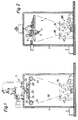
- the vacuum coating system illustrated in FIG. 1, for example, for evaporating coating layers on optical substrates, for example plastic eyeglass lenses 10 here, comprises a recipient 1 that can be evacuated via a vacuum pump 2.
- this recipient 1 there is a reversible carrier device 3 with a plurality, here two recognizable reversible carriers 21 arranged radially around a circular carrier plate 23, each of which is supported on an axis of rotation 22 which can temporarily be rotated through 180 °, each reversible carrier 21 being means for clamping holding a substrate to be coated on both sides or for holding two substrates to be coated on one side (not shown).
- an evaporation source 100 which here comprises a so-called electron beam gun with a filament 15, the emerging electrons of which, after being heated, are bundled in a radiation device in a focusing device 16.
- the electron beam can be generated by a tungsten cathode connected to negative high voltage and pre-focused with a shaped Wehnelt cylinder. This electron beam can now be deflected by deflecting magnet means 13 into a crucible 17 in which the vapor deposition material is located.
- the turning means comprise a ring gear 25 projecting circumferentially from the carrier plate 23, in each of which a driving gear 24 engages, which is in operative connection with the axis of rotation 22 of the turning carrier 21 and with a further, temporarily rotatable counter ring gear 26.
- Such a device allows, according to the invention, to vaporize the surfaces of the substrates spanned on the support means facing the evaporation source first and then, without stopping the evaporation source, quickly turning the support means with the substrates and the surfaces of the evaporation source facing the evaporation source Substrates are also vapor-deposited, after which a cyclical exchange of evaporation sources takes place in order to apply a further coating layer to the substrate surfaces within a new vapor deposition process.
- All substrates are preferably turned over simultaneously and without interrupting the vapor deposition stream 99.
- the vaporization jet is temporarily directed onto a pivotable diaphragm 14 and thus the turning carrier means are covered with the substrates against the vapor deposition stream 99.
Landscapes
- Chemical & Material Sciences (AREA)
- Chemical Kinetics & Catalysis (AREA)
- Engineering & Computer Science (AREA)
- Materials Engineering (AREA)
- Mechanical Engineering (AREA)
- Metallurgy (AREA)
- Organic Chemistry (AREA)
- Physical Vapour Deposition (AREA)
- Surface Treatment Of Optical Elements (AREA)
Abstract
Beim Verfahren zum Aufdampfen von Vergütungsschichten auf Flächen optischer Substrate (10), wie Kunststoff-Brillengläser, welche auf Trägermittel aufspannbar sind, die sich in einem evakuierbaren Rezipienten (1) oberhalb oder unterhalb von auswechselbaren Verdampfungsquellen (100) befinden, wird jeweils innerhalb eines Bedampfungsvorganges zur Erzeugung einer Vergütungsschicht zunächst die der Verdampfungsquelle zugewendeten Flächen der auf Trägermittel (21) aufgespannten Substrate bedampft und dann, ohne Stillsetzung der Verdampfungsquelle, die Trägermittel mit den Substraten rasch gewendet und die nun der Verdampfungsquelle zugewendeten Flächen der Substrate ebenfalls bedampft werden, wonach ein zyklisches Auswechseln von Verdampfungsquellen erfolgt zum Aufbringen jeweils einer weiteren Vergütungsschicht auf die Substratflächen innerhalb eines neuen Bedampfungsvorganges.
Description
Die vorliegende Erfindung betrifft ein Verfahren zum Aufdampfen von Vergütungsschichten auf Flächen optischer Substrate, wie Kunststoff-Brillengläser, welche auf Trägermittel aufspannbar sind, die sich in einem evakuierbaren Rezipienten oberhalb oder unterhalb von auswechselbaren Verdampfungsquellen befinden.The present invention relates to a method for evaporating coating layers on surfaces of optical substrates, such as plastic spectacle lenses, which can be clamped onto carrier means which are located in an evacuable recipient above or below interchangeable evaporation sources.
Bei allen solchen bekannten Verfahren zum Aufdampfen von mindestens einer Oberflächenschicht auf optische Substrate, insbesondere Brillengläser, im Vakuum, werden eine vorgegebene Anzahl solcher Substrate nach dem Aufdampfen von in der Regel mehreren Schichten aus der Ebene, in welcher die Substratflächen der Wirkung der auswechselbaren Verdampfungsquellen ausgesetzt waren, einzeln oder gruppenweise herausbewegt und nochmals eine gleiche Anzahl Substratflächen in diese Ebene hineinbewegt, um diese ebenfalls nachfolgend einmal oder mehrmals zu bedampfen, m. a. W. werden zunächst auf den Substratflächen der einen Seite der Substrate die einzelnen Vergütungsschichten nacheinander aufgedampft, dann die Substrate gewendet und dann die anderen Substratflächen bedampft.In all such known methods for the vapor deposition of at least one surface layer on optical substrates, in particular spectacle lenses, in vacuo, a predetermined number of such substrates after the vapor deposition of generally several layers from the plane in which the substrate surfaces reflect the action of the exchangeable evaporation sources were exposed, moved out individually or in groups and again moved an equal number of substrate areas into this level in order to subsequently vaporize them one or more times, ma. W. First the individual coating layers are evaporated on the substrate areas on one side of the substrates, then the substrates turned and then evaporated the other substrate surfaces.
Solche Verfahren sind aber sehr aufwendig, da nach jedem Bedampfungsvorgang die Verdampfungsquelle abgeschaltet und, nach Abkühlung, für eine neue Vergütungsschicht eine neue Quelle eingesetzt werden muss. Dies wiederholt sich dann alles nochmals bei der Beschichtung der Flächen der dann gewendeten Substrate.However, such methods are very complex since the evaporation source is switched off after each evaporation process and, after cooling, a new source has to be used for a new coating layer. This is then repeated again when the surfaces of the substrates then turned are coated.
Zudem besteht durch das vielmalige Aufheizen der Verdampfungsquellen, welche beispielsweise Elektronenstrahl-Verdampfer oder widerstandsbeheizte thermische Verdampfer sein können, die Gefahr einer Zersetzung der Aufdampfmaterialien sowie der Suboxyd-Bildung und der daraus resultierenden Brechwert-Änderungen.In addition, due to the multiple heating of the evaporation sources, which can be, for example, electron beam evaporators or resistance-heated thermal evaporators, there is a risk of decomposition of the vapor deposition materials and of suboxide formation and the resulting changes in refractive index.
Es ist deshalb Aufgabe der vorliegenden Erfindung, ein Verfahren der vorgenannten Art zu schaffen, bei dem die vorgenannten Nachteile vermieden werden.It is therefore an object of the present invention to provide a method of the aforementioned type in which the aforementioned disadvantages are avoided.
Dies wird beim Verfahren zum Aufdampfen von Vergütungsschichten auf Flächen optischer Substrate, wie Kunststoff-Brillengläser, welche auf Trägermittel aufspannbar sind, die sich in einem evakuierbaren Rezipienten oberhalb oder unterhalb von auswechselbaren Verdampfungsquellen befinden, erfindungsgemäss dadurch erreicht, dass jeweils innerhalb eines Bedampfungsvorganges zur Erzeugung einer Vergütungsschicht zunächst die der Verdampfungsquelle zugewendeten Flächen der auf Trägermittel aufgespannten Substrate bedampft und dann, ohne Stillsetzung der Verdampfungsquelle, die Trägermittel mit den Substraten rasch gewendet und die nun der Verdampfungsquelle zugewendeten Flächen der Substrate ebenfalls bedampft werden, wonach ein zyklisches Auswechseln von Verdampfungsquellen erfolgt zum Aufbringen jeweils einer weiteren Vergütungsschicht auf die Substratflächen innerhalb eines neuen Bedampfungsvorganges.This is the case for the method for the vapor deposition of coating layers on surfaces of optical substrates, such as plastic spectacle lenses, which are placed on carrier means can be clamped, which are located in an evacuable recipient above or below interchangeable evaporation sources, achieved according to the invention in that, in each case during an evaporation process in order to produce a coating layer, the surfaces of the substrates spanned on the carrier means that are facing the evaporation source are first vaporized and then, without stopping the evaporation source, the carrier means with the substrates are quickly turned over and the surfaces of the substrates now facing the evaporation source are also vaporized, after which a cyclical exchange of evaporation sources takes place in order to apply a further coating layer to the substrate surfaces within a new vapor deposition process.
Durch diese Massnahmen wird nun das zyklische Auswechseln der Verdampfungsquellen um die Hälfte reduziert und damit auch deren Aufheizung, was wiederum die Gefahr einer Zersetzung der Aufdampfmaterialien sowie der Suboxyd-Bildung und der daraus resultierenden Brechwert-Änderungen wesentlich verringert.These measures now reduce the cyclical replacement of the evaporation sources by half and thus also their heating, which in turn significantly reduces the risk of decomposition of the vapor deposition materials and the formation of suboxides and the resulting changes in refractive index.
Vorzugsweise werden alle Substrate gleichzeitig und ohne Unterbrechung des Aufdampfstromes gewendet.All substrates are preferably turned over simultaneously and without interrupting the vapor deposition stream.
Bei träge wendenden Substraten hingegen, beispielsweise auf kalottenförmigen Wendeträgern, wird während der Wendezeit der Bedampfungsstrahl temporär auf eine einschwenkbare Blende gerichtet und damit die wendenden Trägermittel mit den Substraten gegen den Aufdampfstrom abgedeckt.In the case of sluggishly turning substrates, however, for example on dome-shaped reversing carriers, the vaporization jet is temporarily directed onto a pivotable diaphragm during the turning time and thus the turning carrier means are covered with the substrates against the vapor deposition stream.
Das erfindungsgemässe Verfahren ist nachfolgend anhand von beispielsweisen Ausführungsformen einer Vakuum-Beschichtungsanlage anhand der Zeichnung näher erläutert. Es zeigen:
- Fig. 1
- im Längsschnitt in schematischer, vereinfachter Darstellung eine Vakuum-Beschichtungsanlage zum Bedampfen mehrerer optischer Substrate auf einer Wendeträger-Vorrichtung;
und - Fig. 2
- eine Ausführungsvariante der Anordnung gemäss Fig.1.
- Fig. 1
- in longitudinal section in a schematic, simplified representation, a vacuum coating system for vapor deposition of several optical substrates on a reversible carrier device;
and - Fig. 2
- an embodiment of the arrangement according to Fig.1.
Die in Fig. 1 beispielsweise veranschaulichte Vakuum-Beschichtungsanlage zum Aufdampfen von Vergütungsschichten auf optische Substrate, beispielsweise hier Kunststoff-Brillenglaser 10, umfasst einen, über eine Vakuum-Pumpe 2 evakuierbaren Rezipienten 1.The vacuum coating system illustrated in FIG. 1, for example, for evaporating coating layers on optical substrates, for example
Im oberen Kammerbereich dieses Rezipienten 1 befindet sich eine Wendeträger-Vorrichtung 3 mit einer Mehrzahl, hier zwei erkennbare radial um eine kreisförmige Trägerplatte 23 angeordnete Wendeträger 21, die je an einer, temporär um 180° verdrehbaren Drehachse 22 abgestützt sind, wobei jeder Wendeträger 21 Mittel zum klemmenden Festhalten eines beidseitig zu beschichtenden Substrates oder zum Festhalten von zwei einseitig zu beschichtenden Substraten umfasst (nicht gezeigt).In the upper chamber area of this
Im unteren Bereich des Rezipienten 1 ist eine Verdampfungsquelle 100 angedeutet, die hier eine sogenannte Elektronenstrahlkanone mit einem Heizfaden 15 umfasst, dessen austretende Elektronen nach seiner Erhitzung in einer Fokussierungseinrichtung 16 strahlenförmig gebündelt werden. Beispielsweise kann der Elektronenstrahl von einer an negativer Hochspannung liegenden Wolframkathode erzeugt und mit einem geformten Wehnelt-Zylinder vorfokussiert werden. Dieser Elektronenstrahl lässt sich nun durch Umlenkmagnetmittel 13 in einen Tiegel 17 umlenken, in dem sich das Aufdampfmaterial befindet.In the lower region of the
Zum Betreiben bzw. Bedienen der im evakuierten Rezipienten 1 zu bewegenden Apparateteile, wie etwa eine Blende 14 u. dgl., sind Einrichtungen mit Betätigungsbauteilen notwendig, die von aussen in den Vakuumraum hineinreichen (nicht gezeigt). Da der Aufbau und die Funktionsweise solcher Vakuumaufdampfanlagen weiters soweit bekannt sind, erübrigt sich eine nähere Konstruktionsbeschreibung.To operate or operate the apparatus parts to be moved in the evacuated
Wesentlich ist hier zunächst, dass an den Wendeträgern 21 resp. Drehachsen 22 Wendemittel zum gleichzeitigen Wenden aller Wendeträger angreifen. Hierfür umfassen die Wendemittel einen von der Trägerplatte 23 umfänglich abragenden Zahnkranz 25, in den je ein Mitnahmezahnrad 24 eingreift, das mit der Drehachse 22 der Wendeträger 21 sowie mit einem weiteren, temporär verdrehbaren Gegenzahnkranz 26 in Wirkungsverbindung steht.It is essential here first that on the reversing
Damit ist es möglich, zu geeigneter Zeit den Gegenzahnkranz 26 relativ zum Zahnkranz 25 soweit zu verdrehen, bis die Wendeträger 21 mit ihren Substraten über das jeweilige Mitnahmezahnrad 24 um 180° gedreht sind. Dies erfolgt in Bruchteilen einer Sekunde, also so schnell, dass der Bedampfungsstrahl 99 nicht unterbrochen werden muss.It is thus possible, at a suitable time, to rotate the
Eine solche Einrichtung gestattet, dass erfindungsgemäss jeweils innerhalb eines Bedampfungsvorganges zur Erzeugung einer Vergütungsschicht zunächst die der Verdampfungsquelle zugewendeten Flächen der auf Trägermittel aufgespannten Substrate bedampft und dann, ohne Stillsetzung der Verdampfungsquelle, die Trägermittel mit den Substraten rasch gewendet und die nun der Verdampfungsquelle zugewendeten Flächen der Substrate ebenfalls bedampft werden, wonach ein zyklisches Auswechseln von Verdampfungsquellen erfolgt zum Aufbringen jeweils einer weiteren Vergütungsschicht auf die Substratflächen innerhalb eines neuen Bedampfungsvorganges.Such a device allows, according to the invention, to vaporize the surfaces of the substrates spanned on the support means facing the evaporation source first and then, without stopping the evaporation source, quickly turning the support means with the substrates and the surfaces of the evaporation source facing the evaporation source Substrates are also vapor-deposited, after which a cyclical exchange of evaporation sources takes place in order to apply a further coating layer to the substrate surfaces within a new vapor deposition process.
Durch diese Massnahmen wird nun das zyklische Auswechseln der Verdampfungsquellen um die Hälfte reduziert und damit auch deren Aufheizung, was wiederum die Gefahr einer Zersetzung der Aufdampfmaterialien sowie der Suboxyd-Bildung und der daraus resultierenden Brechwert-Änderungen wesentlich verringert.These measures now reduce the cyclical replacement of the evaporation sources by half and thus also their heating, which in turn significantly reduces the risk of decomposition of the vapor deposition materials and the formation of suboxides and the resulting changes in refractive index.
Vorzugsweise werden alle Substrate gleichzeitig und ohne Unterbrechung des Aufdampfstromes 99 gewendet. Bei träge wendenden Substraten hingegen, beispielsweise auf kalottenförmigen Wendeträgern gemäss Fig. 2, wird während der Wendezeit der Kalotten 33 mit den Substraten 10 mittels Wendevorrichtung 19 der Bedampfungsstrahl temporär auf eine einschwenkbare Blende 14 gerichtet und damit die wendenden Trägermittel mit den Substraten gegen den Aufdampfstrom 99 abgedeckt.All substrates are preferably turned over simultaneously and without interrupting the
Claims (3)
dadurch gekennzeichnet, dass
jeweils innerhalb eines Bedampfungsvorganges zur Erzeugung einer Vergütungsschicht zunächst die der Verdampfungsquelle zugewendeten Flächen der auf Trägermittel aufgespannten Substrate bedampft und dann, ohne Stillsetzung der Verdampfungsquelle, die Trägermittel mit den Substraten rasch gewendet und die nun der Verdampfungsquelle zugewendeten Flächen der Substrate ebenfalls bedampft werden, wonach ein zyklisches Auswechseln von Verdampfungsquellen erfolgt zum Aufbringen jeweils einer weiteren Vergütungsschicht auf die Substratflächen innerhalb eines neuen Bedampfungsvorganges.Process for evaporating coating layers on surfaces of optical substrates, such as plastic spectacle lenses, which can be clamped onto carrier means which are located in an evacuable recipient above or below exchangeable evaporation sources,
characterized in that
each within a vapor deposition process to produce a coating layer, the areas of the substrates spanned on the support means facing the evaporation source are vaporized and then, without stopping the evaporation source, the support means with the substrates are quickly turned over and the areas of the substrates now facing the evaporation source are also vaporized, after which a Cyclical replacement of evaporation sources takes place in each case to apply a further coating layer to the substrate surfaces within a new vapor deposition process.
Applications Claiming Priority (3)
| Application Number | Priority Date | Filing Date | Title |
|---|---|---|---|
| CH01199/96A CH691307A5 (en) | 1996-05-10 | 1996-05-10 | A method for vapor deposition of coating layers on optical substrates. |
| CH1199/96 | 1996-05-10 | ||
| CH119996 | 1996-05-10 |
Publications (3)
| Publication Number | Publication Date |
|---|---|
| EP0806491A2 true EP0806491A2 (en) | 1997-11-12 |
| EP0806491A3 EP0806491A3 (en) | 1997-11-19 |
| EP0806491B1 EP0806491B1 (en) | 2002-01-16 |
Family
ID=4204829
Family Applications (1)
| Application Number | Title | Priority Date | Filing Date |
|---|---|---|---|
| EP97107372A Expired - Lifetime EP0806491B1 (en) | 1996-05-10 | 1997-05-05 | Vapor deposition method for coating optical substrates |
Country Status (4)
| Country | Link |
|---|---|
| EP (1) | EP0806491B1 (en) |
| JP (1) | JP4193951B2 (en) |
| CH (1) | CH691307A5 (en) |
| DE (1) | DE59705983D1 (en) |
Cited By (2)
| Publication number | Priority date | Publication date | Assignee | Title |
|---|---|---|---|---|
| EP2236649A1 (en) * | 2009-04-02 | 2010-10-06 | Protec Surface Technologies S.r.L. | Deposition process of a nanocomposite film and apparatus therefor |
| CN120210757A (en) * | 2025-05-28 | 2025-06-27 | 望江县天成光学仪器股份有限公司 | Full-automatic vacuum coating machine for optical lenses and control system thereof |
Families Citing this family (1)
| Publication number | Priority date | Publication date | Assignee | Title |
|---|---|---|---|---|
| JP4601368B2 (en) * | 2004-09-22 | 2010-12-22 | 新明和工業株式会社 | Ion processing equipment |
Family Cites Families (5)
| Publication number | Priority date | Publication date | Assignee | Title |
|---|---|---|---|---|
| US3396696A (en) * | 1966-10-06 | 1968-08-13 | Ralph F. Becker | Lens turner for high vacuum evaporators |
| DE1913318B2 (en) * | 1969-03-15 | 1972-01-27 | Kodak Ag, 7000 Stuttgart | VACUUM EVAPORATION OR CATHODE ATTENUATION SYSTEM |
| JPS58107484A (en) * | 1981-12-19 | 1983-06-27 | Olympus Optical Co Ltd | Reverse type vapor deposition apparatus in thin film forming apparatus |
| JPS58123868A (en) * | 1982-01-18 | 1983-07-23 | Fujitsu Ltd | Forming apparatus for thin film |
| CH668430A5 (en) * | 1986-07-31 | 1988-12-30 | Satis Vacuum Ag | VACUUM COATING SYSTEM FOR OPTICAL SUBSTRATES. |
-
1996
- 1996-05-10 CH CH01199/96A patent/CH691307A5/en not_active IP Right Cessation
-
1997
- 1997-05-05 EP EP97107372A patent/EP0806491B1/en not_active Expired - Lifetime
- 1997-05-05 DE DE59705983T patent/DE59705983D1/en not_active Expired - Lifetime
- 1997-05-07 JP JP11715097A patent/JP4193951B2/en not_active Expired - Lifetime
Cited By (2)
| Publication number | Priority date | Publication date | Assignee | Title |
|---|---|---|---|---|
| EP2236649A1 (en) * | 2009-04-02 | 2010-10-06 | Protec Surface Technologies S.r.L. | Deposition process of a nanocomposite film and apparatus therefor |
| CN120210757A (en) * | 2025-05-28 | 2025-06-27 | 望江县天成光学仪器股份有限公司 | Full-automatic vacuum coating machine for optical lenses and control system thereof |
Also Published As
| Publication number | Publication date |
|---|---|
| EP0806491A3 (en) | 1997-11-19 |
| CH691307A5 (en) | 2001-06-29 |
| EP0806491B1 (en) | 2002-01-16 |
| JP4193951B2 (en) | 2008-12-10 |
| DE59705983D1 (en) | 2002-02-21 |
| JPH1068065A (en) | 1998-03-10 |
Similar Documents
| Publication | Publication Date | Title |
|---|---|---|
| DE4341173B4 (en) | Device and method for depositing different materials on a substrate | |
| CH668430A5 (en) | VACUUM COATING SYSTEM FOR OPTICAL SUBSTRATES. | |
| EP0396099B1 (en) | Arrangement for removal of material from a target | |
| EP0806492B1 (en) | Substrate holder for vacuum coating apparatus | |
| CH681308A5 (en) | ||
| DE4126236A1 (en) | ROTATING MAGNETRON CATODE AND METHOD FOR USE | |
| EP0124829A1 (en) | Beam heating evaporation apparatus for the vapour coating of several materials | |
| EP1626433A9 (en) | Magnetron sputtering device, cylinder cathode and a method of applying thin multi-component films to a substrate | |
| EP0806493A2 (en) | Vapor deposition apparatus for coating optical substrates | |
| EP1722005B1 (en) | Method of using a sputtering cathode together with a target | |
| CH692000A5 (en) | Coating chamber, substrate carrier therefor, method of vacuum deposition and coating methods. | |
| WO2016202468A1 (en) | Device, method and use for the coating of lenses | |
| EP0806491B1 (en) | Vapor deposition method for coating optical substrates | |
| DE102023200603A1 (en) | Method for producing a mirror arrangement, and coating system | |
| DE102012205615A1 (en) | Coating for producing an optical element having a substrate, whose surface has optically active coating, comprises e.g. placing substrate in substrate plane, generating ions, and deflecting ions moving toward substrate by an electric field | |
| DE3902862A1 (en) | METHOD FOR REMOVING PARTICLES ON SUBSTRATE SURFACES | |
| DE69305725T2 (en) | Magnetron sputtering device and thin film coating process | |
| DE3636684A1 (en) | Filter for compensation of the brightness fall-off in the image plane of a lens | |
| DE2337204A1 (en) | Spectacle lens vapour deposition holder - comprises turntable with radial axis rotatable twin lens holders | |
| EP1737997A2 (en) | Device for coating both sides of a substrate with a hydrophobic layer | |
| DE2029014A1 (en) | Vacuum evaporation device | |
| DE102009005513A1 (en) | Method for long-term stable coating of substrate, comprises moving the substrate through a coating chamber and then coating in which evaporation materials arranged in a crucible are evaporated by electron beam | |
| DE4405598C1 (en) | Coating method and coating apparatus | |
| DE4419167B4 (en) | Device for coating a substrate | |
| DE10155120A1 (en) | Coating substrate using pulsed cathodic arc erosion of sacrificial cathode comprises locally and/or temporarily controlling initiation of pulsed erosion |
Legal Events
| Date | Code | Title | Description |
|---|---|---|---|
| PUAI | Public reference made under article 153(3) epc to a published international application that has entered the european phase |
Free format text: ORIGINAL CODE: 0009012 |
|
| PUAL | Search report despatched |
Free format text: ORIGINAL CODE: 0009013 |
|
| AK | Designated contracting states |
Kind code of ref document: A2 Designated state(s): DE FR GB IT |
|
| AK | Designated contracting states |
Kind code of ref document: A3 Designated state(s): DE FR GB IT |
|
| 17P | Request for examination filed |
Effective date: 19980519 |
|
| 17Q | First examination report despatched |
Effective date: 19990715 |
|
| GRAG | Despatch of communication of intention to grant |
Free format text: ORIGINAL CODE: EPIDOS AGRA |
|
| GRAG | Despatch of communication of intention to grant |
Free format text: ORIGINAL CODE: EPIDOS AGRA |
|
| GRAH | Despatch of communication of intention to grant a patent |
Free format text: ORIGINAL CODE: EPIDOS IGRA |
|
| GRAH | Despatch of communication of intention to grant a patent |
Free format text: ORIGINAL CODE: EPIDOS IGRA |
|
| GRAA | (expected) grant |
Free format text: ORIGINAL CODE: 0009210 |
|
| REG | Reference to a national code |
Ref country code: GB Ref legal event code: IF02 |
|
| AK | Designated contracting states |
Kind code of ref document: B1 Designated state(s): DE FR GB IT |
|
| REF | Corresponds to: |
Ref document number: 59705983 Country of ref document: DE Date of ref document: 20020221 |
|
| GBT | Gb: translation of ep patent filed (gb section 77(6)(a)/1977) |
Effective date: 20020406 |
|
| ET | Fr: translation filed | ||
| PLBE | No opposition filed within time limit |
Free format text: ORIGINAL CODE: 0009261 |
|
| STAA | Information on the status of an ep patent application or granted ep patent |
Free format text: STATUS: NO OPPOSITION FILED WITHIN TIME LIMIT |
|
| 26N | No opposition filed | ||
| REG | Reference to a national code |
Ref country code: FR Ref legal event code: CD Ref country code: FR Ref legal event code: CA |
|
| REG | Reference to a national code |
Ref country code: FR Ref legal event code: PLFP Year of fee payment: 20 |
|
| PGFP | Annual fee paid to national office [announced via postgrant information from national office to epo] |
Ref country code: GB Payment date: 20160630 Year of fee payment: 20 Ref country code: DE Payment date: 20160620 Year of fee payment: 20 |
|
| PGFP | Annual fee paid to national office [announced via postgrant information from national office to epo] |
Ref country code: IT Payment date: 20160527 Year of fee payment: 20 Ref country code: FR Payment date: 20160527 Year of fee payment: 20 |
|
| REG | Reference to a national code |
Ref country code: DE Ref legal event code: R071 Ref document number: 59705983 Country of ref document: DE |
|
| REG | Reference to a national code |
Ref country code: GB Ref legal event code: PE20 Expiry date: 20170504 |
|
| PG25 | Lapsed in a contracting state [announced via postgrant information from national office to epo] |
Ref country code: GB Free format text: LAPSE BECAUSE OF EXPIRATION OF PROTECTION Effective date: 20170504 |