EP0806358A1 - Méthode et dispositif de transfert d'articles - Google Patents
Méthode et dispositif de transfert d'articles Download PDFInfo
- Publication number
- EP0806358A1 EP0806358A1 EP97107588A EP97107588A EP0806358A1 EP 0806358 A1 EP0806358 A1 EP 0806358A1 EP 97107588 A EP97107588 A EP 97107588A EP 97107588 A EP97107588 A EP 97107588A EP 0806358 A1 EP0806358 A1 EP 0806358A1
- Authority
- EP
- European Patent Office
- Prior art keywords
- stacking belt
- belt conveyor
- objects
- packing
- carrier
- Prior art date
- Legal status (The legal status is an assumption and is not a legal conclusion. Google has not performed a legal analysis and makes no representation as to the accuracy of the status listed.)
- Granted
Links
- 238000000034 method Methods 0.000 title claims description 27
- 238000012546 transfer Methods 0.000 claims description 66
- 238000012856 packing Methods 0.000 claims description 44
- 238000004806 packaging method and process Methods 0.000 claims description 31
- 238000012432 intermediate storage Methods 0.000 claims description 9
- 238000012545 processing Methods 0.000 claims description 5
- 238000001514 detection method Methods 0.000 claims description 4
- 235000009508 confectionery Nutrition 0.000 description 64
- 230000015572 biosynthetic process Effects 0.000 description 9
- 238000005755 formation reaction Methods 0.000 description 9
- 230000005540 biological transmission Effects 0.000 description 7
- 238000011144 upstream manufacturing Methods 0.000 description 5
- 230000002950 deficient Effects 0.000 description 4
- 235000013736 caramel Nutrition 0.000 description 3
- 230000008878 coupling Effects 0.000 description 3
- 238000010168 coupling process Methods 0.000 description 3
- 238000005859 coupling reaction Methods 0.000 description 3
- 239000000969 carrier Substances 0.000 description 2
- 238000013461 design Methods 0.000 description 2
- 238000003780 insertion Methods 0.000 description 2
- 230000037431 insertion Effects 0.000 description 2
- 238000004519 manufacturing process Methods 0.000 description 2
- 230000002093 peripheral effect Effects 0.000 description 2
- 238000013459 approach Methods 0.000 description 1
- 229940112822 chewing gum Drugs 0.000 description 1
- 235000015218 chewing gum Nutrition 0.000 description 1
- 238000010276 construction Methods 0.000 description 1
- 230000001419 dependent effect Effects 0.000 description 1
- 238000011161 development Methods 0.000 description 1
- 230000002349 favourable effect Effects 0.000 description 1
- 238000007654 immersion Methods 0.000 description 1
- 210000000629 knee joint Anatomy 0.000 description 1
- 239000005022 packaging material Substances 0.000 description 1
- 238000002360 preparation method Methods 0.000 description 1
- 238000004886 process control Methods 0.000 description 1
- 230000001360 synchronised effect Effects 0.000 description 1
Images


Classifications
-
- B—PERFORMING OPERATIONS; TRANSPORTING
- B65—CONVEYING; PACKING; STORING; HANDLING THIN OR FILAMENTARY MATERIAL
- B65B—MACHINES, APPARATUS OR DEVICES FOR, OR METHODS OF, PACKAGING ARTICLES OR MATERIALS; UNPACKING
- B65B35/00—Supplying, feeding, arranging or orientating articles to be packaged
- B65B35/10—Feeding, e.g. conveying, single articles
- B65B35/20—Feeding, e.g. conveying, single articles by reciprocating or oscillatory pushers
- B65B35/205—Feeding, e.g. conveying, single articles by reciprocating or oscillatory pushers linked to endless conveyors
-
- B—PERFORMING OPERATIONS; TRANSPORTING
- B65—CONVEYING; PACKING; STORING; HANDLING THIN OR FILAMENTARY MATERIAL
- B65B—MACHINES, APPARATUS OR DEVICES FOR, OR METHODS OF, PACKAGING ARTICLES OR MATERIALS; UNPACKING
- B65B35/00—Supplying, feeding, arranging or orientating articles to be packaged
- B65B35/10—Feeding, e.g. conveying, single articles
- B65B35/26—Feeding, e.g. conveying, single articles by rotary conveyors
-
- B—PERFORMING OPERATIONS; TRANSPORTING
- B65—CONVEYING; PACKING; STORING; HANDLING THIN OR FILAMENTARY MATERIAL
- B65B—MACHINES, APPARATUS OR DEVICES FOR, OR METHODS OF, PACKAGING ARTICLES OR MATERIALS; UNPACKING
- B65B35/00—Supplying, feeding, arranging or orientating articles to be packaged
- B65B35/30—Arranging and feeding articles in groups
- B65B35/40—Arranging and feeding articles in groups by reciprocating or oscillatory pushers
- B65B35/405—Arranging and feeding articles in groups by reciprocating or oscillatory pushers linked to endless conveyors
-
- B—PERFORMING OPERATIONS; TRANSPORTING
- B65—CONVEYING; PACKING; STORING; HANDLING THIN OR FILAMENTARY MATERIAL
- B65G—TRANSPORT OR STORAGE DEVICES, e.g. CONVEYORS FOR LOADING OR TIPPING, SHOP CONVEYOR SYSTEMS OR PNEUMATIC TUBE CONVEYORS
- B65G29/00—Rotary conveyors, e.g. rotating discs, arms, star-wheels or cones
-
- B—PERFORMING OPERATIONS; TRANSPORTING
- B65—CONVEYING; PACKING; STORING; HANDLING THIN OR FILAMENTARY MATERIAL
- B65G—TRANSPORT OR STORAGE DEVICES, e.g. CONVEYORS FOR LOADING OR TIPPING, SHOP CONVEYOR SYSTEMS OR PNEUMATIC TUBE CONVEYORS
- B65G47/00—Article or material-handling devices associated with conveyors; Methods employing such devices
- B65G47/74—Feeding, transfer, or discharging devices of particular kinds or types
- B65G47/82—Rotary or reciprocating members for direct action on articles or materials, e.g. pushers, rakes, shovels
-
- B—PERFORMING OPERATIONS; TRANSPORTING
- B65—CONVEYING; PACKING; STORING; HANDLING THIN OR FILAMENTARY MATERIAL
- B65G—TRANSPORT OR STORAGE DEVICES, e.g. CONVEYORS FOR LOADING OR TIPPING, SHOP CONVEYOR SYSTEMS OR PNEUMATIC TUBE CONVEYORS
- B65G47/00—Article or material-handling devices associated with conveyors; Methods employing such devices
- B65G47/74—Feeding, transfer, or discharging devices of particular kinds or types
- B65G47/84—Star-shaped wheels or devices having endless travelling belts or chains, the wheels or devices being equipped with article-engaging elements
- B65G47/846—Star-shaped wheels or wheels equipped with article-engaging elements
- B65G47/847—Star-shaped wheels or wheels equipped with article-engaging elements the article-engaging elements being grippers
Definitions
- the invention relates to a method for the transfer of objects, in which each object is individually picked up between opposing holding jaws which are pivotably mounted on a rotating carrier and is transported with the carrier in the circumferential direction thereof.
- the invention further relates to a device, in particular for carrying out the aforementioned method, with pairs of holding jaws which are pivotably mounted on a rotating support for the individual detection of an object.
- sweets e.g. soft or hard caramels
- a transfer wheel with the same effective range, which in turn transfers the objects to a wrapping wheel with speed compensation (WO 93/10005).
- Such packaging machines in particular candy packaging machines, based on the "rotation principle" of the transfer elements, can work in the high-performance range with packaging speeds of up to approximately 1,500 pieces per minute and are extremely efficient. Difficulties with such high-performance packaging machines are the equally economical further process design, for example for the formation of articles packed into bars.
- the invention is therefore based on the object of specifying a method and a device of the type mentioned at the outset which allow objects, possibly also after prior individual packaging, to be grouped together at high speed and made stackable, possibly to form a first or Further packaging to bars.
- the aforementioned object is achieved according to the invention by a method for the transfer of objects, in particular for packaging machines, in which each object is individually picked up between opposing holding jaws, which are pivotably mounted on a rotating carrier, transported with the carrier in the circumferential direction thereof and to form a group of objects arranged adjacent to one another is delivered substantially tangentially to a stacking belt conveyor and the objects are then moved on in groups by the stacking belt conveyor and are released in groups by the latter.
- the method according to the invention has the advantage that it is based on the conveyance of the objects, e.g. Candies, which is possible with a packaging machine, while maintaining this mode of operation which enables high-performance operation, also to arrange individual objects in groups, in preparation for forming a bar, in which the objects are contained one beside the other, packaged or unwrapped.
- the holding jaws for the objects arranged on the rotating carrier can be pivoted about an axis running essentially parallel to the axis of rotation of the carrier, this relative pivoting movement of the pairs of holding jaws for the basic rotational movement of the carrier advantageously adapting the speed between the carrier and the downstream stacking belt conveyor, the speed ratio being widely variable.
- the circulating speed of the carrier is preferably greater than a conveying speed, in particular circulating speed, of a stacking belt of the stacking belt conveyor.
- each group of objects grouped in the stacking belt conveyor is discharged from the stacking belt conveyor in a delivery area by means of an ejection device that operates essentially at right angles to the conveying direction of the stacking belt conveyor, a pressure-conveying principle preferably being used.
- the group of objects is preferably discharged onto an intermediate storage device which can be moved essentially parallel to the conveying direction of the stacking belt conveyor, from which, in turn, using a pulling principle, the objects are jointly transferred from the intermediate storage device to a feed device of a processing machine, in particular packaging machine, such as e.g. be supported by a pole packer.
- the aforementioned object is achieved in a device for the transfer of objects, in particular for packaging machines, with pairs of holding jaws which are pivotably mounted on a rotating carrier, for the individual detection of an object between the holding jaws of a pair of holding jaws in a receiving region of the carrier, the movement of the Object with the carrier in the same circumferential direction and delivery of the object in a delivery region of the carrier, in particular for carrying out the aforementioned method, according to the invention solved in that a stacking belt conveyor with a revolving stacking belt is arranged downstream of the carrier, for the group-wise reception of the items fed individually by the pairs of holding jaws of the carrier into a plurality of packing compartments of the stacking belt conveyor that hold side by side.
- the aforesaid device is particularly advantageous since, while maintaining individual treatment of objects in a packaging machine and while maintaining the principle of "rotating" transmission, it creates the possibility of grouping a plurality of objects at extremely high working speeds and of further treatment, e.g. to form bars from a large number of individual, pre-grouped objects, packaged or unwrapped.
- the stacking belt conveyor has a revolving stacking belt with a plurality of projections, to form the packing compartments with a counter bearing arranged in a stationary manner between a receiving section of the stacking belt conveyor and a discharge section thereof.
- the pairs of holding jaws of the carrier in turn have movable holding jaws, between which the object in question is directly received and supported, the holding jaws being movable and in particular rotatable relative to the pivoting housings which support the holding jaws, so that it is possible, for example, the objects gripped by the holding jaws on the way between the receiving area of the carrier and the delivery area of the same to the stacking belt conveyor turn by 90 °.
- This can e.g. Prismatic objects in a flat orientation are initially gripped by the holding jaws, but are passed on to the stacking belt conveyor in an upright orientation for group formation and stacking (or vice versa).
- a transverse pushing device is provided in a discharge area of the stacking belt conveyor as an ejection device for pushing out the objects conveyed in groups from the packing compartments of the stacking belt conveyor.
- the objects are transversely shifted in groups for further packaging.
- the latter can also be stopped when objects which are not of the right quality are detected, so that a stage identified as incomplete or at least partially qualitatively inadequate is conveyed away in the conveying direction of the stacking belt conveyor.
- an intermediate storage device in particular an intermediate plate, which can be moved parallel to the conveying direction which the stacking belt occupies in the output region of the stacking belt conveyor.
- a feed belt for feeding the articles in groups to a packaging machine, in particular a bar packer, and a transfer device for simultaneously feeding one or a plurality of groups of articles located in the intermediate storage device to the feed belt can preferably be provided downstream of the intermediate storage device, in particular intermediate plate be provided.
- the rotating carrier is preferably a transfer head which is arranged between a rotating packing head and the stacking belt conveyor and has a housing which rotates about a stationary axis and on which a plurality of pairs of holding jaws is pivotally received, with a pivoting control of the pairs of holding jaws and a separate rotary movement of the holding jaws by a stationary cam plate arrangement that can be adjusted together with the axis.
- the embodiment that includes the packaging of prismatic geometry candies 205, e.g. of soft or hard caramels, especially when preparing the individually wrapped candies 205 for delivery to a bar packer - not shown here - is of course not limited to the handling of this type of item, but can be used for a variety of other, especially small items are to be packed and which are in particular either already individually prepacked or are also to be assembled unpacked into groups and, in particular, to be packed into sticks.
- individual elements of the overall device such as e.g. a transfer head, can also be used in other contexts and machine links.
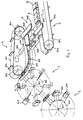
- a revolving packing head 2 In packaging machines of this type, individual pieces of candy, for example separated from a continuous mass strand, can be conveyed to a revolving packing head 2 after picking up and feeding via a gripper wheel and transfer wheel (not shown here) (as is known from WO 93/25440) with regard to its movement mechanics with a similar basic structure as the transfer head 1 has a housing 202 rotating about a stationary axis 201, on each of which a pack jaw pair 204 is pivotally mounted about pivot axes 203, which picks up the candy piece and, while feeding a packaging material section, the candy piece to the individually packaged one Candy 205 packaged without this being shown in detail here.
- the transfer head 1 which, arranged downstream of the packing head 2 and upstream of a stacking belt conveyor 3, also has a housing 102 rotating about a stationary axis 101, on which holding jaw pairs 104 which are pivotably mounted about axes of rotation 103 are pivotably mounted Rotated 90 ° with respect to the orientation of the pairs of packing jaws 204 of the packing head 2 are arranged to receive the individually wrapped candies 205 from the packing head 2 rotating at the same circulating speed, but with the opposite direction of rotation, and for delivery to a stacking belt conveyor 3, which has a significantly lower conveying speed ( Approximately 1/3 of the rotating speed of the rotating housing 102 of the transfer head 1 groups the individually wrapped candies in groups, so that the rotating speed of the respective pair of holding jaws with the individually wrapped hard candy 205 can be adjusted for smooth operation the conveying speed of the group-forming stacking belt conveyor 3 is necessary, this being done by swivel housing 117, that is to say by the articulation of the holding jaw
- the stacking belt conveyor points to the formation of the groups 3 shows a stacking belt 301 with drivers 302, the stacking belt being guided over a deflection roller 303 and having a counter bearing 304 in the region of the reception of the candies 205 from the transfer head 1 and for the further transport of the candy groups.
- the individually packed candies 205 are thus fed from the packing head 2, which has a plurality of pairs of packing jaws 204 that can be pivoted about the stationary axis 201 on the rotating housing 202, to the transfer head 1 arranged upstream of the stacking belt conveyor 3, which supplies the candies 205 through the holding jaw pairs 104, which are pivotably mounted on the housing 102 rotating about the stationary axis 101, and leads to the stacking belt conveyor 3, which is arranged tangentially in the orbit of the candies 205.
- the transfer head 1 also has the ability to rotate the candies in their position by 90 °, so that they can not only be passed on in flat format (as recorded), but can also be fed to the stacking belt conveyor 3 for upright processing.
- the stacking belt conveyor 3 has a significantly lower working speed, which is preferably at a maximum of about 50% of the working speed of the upstream conveyors 1 and 2 (generally 1/3 of this working speed), and the formation groups A, B of candies 205 is used for further packaging into bars.
- the stacking belt conveyor 3 has the stacking belt 301 with the drivers 302, which in conjunction with the counter bearing 304 form packing compartments 305, in which in the present case 3 candies 205 are accommodated side by side can be (Fig. 1) or 5 candies 205 can be picked up side by side (Fig. 2, Fig. 13-15).
- the stacking belt 301 is continuously circulated over the deflecting rollers 303.
- a further conveying device 5 which here is formed by a feed belt 501 which, like the stacking belt 301, forms individual transport compartments 503 with carriers 502, in which the fed groups A, B conveyed from candies intermittently and e.g. be fed to a bar packer.
- the further conveying device 5 is designed as a feed belt 501, deflected around the deflection roller 504. With regard to bar packers, however, it is often preferred to feed the groups A, B of candies 205 to a feed chain 505 as a further conveyor and feed path for subsequent packaging of a plurality of groups A, B of objects, as shown in FIGS. 13-15.
- a transfer device 4 is provided, which works in the sense of a cross-conveyance between the stacking belt conveyor 3 and the further conveying device 5 and which is explained in more detail below.
- the candies 205 for the production of flat packs are picked up in the same orientation as by the packing head 2, that is to say passed to the stacking belt conveyor 3 without rotation, as is also the case in the illustration of the transfer process corresponding to this exemplary embodiment.
- Fig. 12b is the case.
- the transfer head 1 is therefore designed in a special way to ensure such a function, as will be explained below with reference to FIGS. 2-11.
- FIG. 2 A process control with forwarding of the candies 205 rotated by 90 ° to the stacking belt conveyor 3 is shown in FIG. 2.
- the candies 205 On the way from picking up the candies 205 from the packing head 2 through the holding jaw pairs 104 of the transfer head 1 to delivery to the stacking belt conveyor 3, the candies 205 must therefore still be rotated through 90 ° while being simultaneously captured by the holding jaw pairs 104.
- This rotational movement preferably takes place only at the end, ie together with an opposing axial movement of the holding jaw pairs 104 to release the candy 205 on the stacking belt 301 of the stacking belt conveyor 3, so that the holding jaw pairs 104 are not only subject to an axial movement, but at the same time are subject to a rotational movement of the holding jaw pairs 104 is superimposed for the rotation of the candies 205 in the upright position.
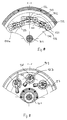
- the transfer head 1 has the central, stationary axis 101, which nevertheless can be rotated in the circumferential direction in particular by 180 °, and which extends between a stationary housing 107 and a bearing plate 108.
- a control cam arrangement 109 as part of a movement control device for the holding jaw pairs 104, is fixed on the stationary axis 101, rotatably connected to the axis 101.
- This control cam arrangement 109 consists of a plurality of cam disks 110, 111, 112, 113, 114 arranged in succession on the stationary axis 101. Together with the stationary axis 106, they can preferably be pivoted through 180 ° in order to change the movement pattern for a rotary movement of the to set up individual holding jaw pairs 104, as will be explained below.
- cams 110-114 could also be structurally combined or separately via e.g. a common adjusting sleeve, which is rotatably received on the stationary axis 106, can be adjusted relative to it by a certain angle.
- a base housing 102 is rotatably mounted on the stationary axis 101 for rotation and is driven by a drive spur gear 116, the drive device not being shown in detail here.
- Shafts 125 for each pair of holding jaws 104 which are rotatably supported in the circumferential direction in the basic housing 102, determine the axes of rotation 103 for the pairs of holding jaws 104, which are accommodated in the swivel housings 117 pivotable about these axes of rotation 103.
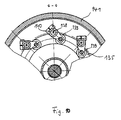
- the pivotal movement of the pivot housing 117 to adjust the transfer speed from the peripheral speed of the transfer head 1 to the Approx. 1/3 of this peripheral speed of the conveyor belt 301 takes place via the double cam plate 113 with which, via control roller pairs 118, roll on the circumference of the double cam plate 113 (see section BB according to FIG. 3) and the control movement on a tubular one Housing approach 119 of the swivel housing 117 transmits.
- a pair of holding jaws 104 with the holding jaws 104a, 104b is oppositely mounted in a part of the fork-shaped swivel housing 117 projecting radially outwards, each holding jaw 104a, 104b being axially movable around the candy 205 on opposing surfaces, with force-locking and tensioning by a spring 106 to seize or release.
- the holding jaws 104a, 104b can also be rotated about a holding jaw axis A in order to pass on the gripped candy 205 (or another object that is currently being processed) in a position that is preferably rotated by 90 ° with respect to the receiving position (for example upright after a flat recording).
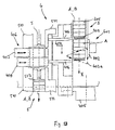
- the movement control device for each pair of holding jaws 104 which gives the holding jaws 104a, 104b both an opposing axial movement and a rotational movement about their holding jaw axis A, has the cam disks 110, 111, 112, the cam disks 111 and 112 the axial movement of the outer holding jaw 104b ( Control cam 111) or the axial movement of the inner holding jaw 104a (cam 112).
- a control roller 120 of a cam lever 121, 122 engages with the cam disks 111, 112, which are each designed as end curves (outer bearing ring), the cam lever 121 having radial guide bodies 123 which are connected to the shaft 125 in a rotationally fixed manner, is surrounded, on the one hand, the transmission of the axial movement received by the control roller 120 to the shaft 125 and, on the other hand, also the transmission of a pivoting movement on this shaft 125, the cam lever 121 itself being rotatably mounted on the shaft 125 and also rotatably via an insert 115 (outer bearing ring) in the outer circumferential region of the rotating basic housing 102.
- the axial movement for the inner holding jaw 104a is controlled via the control roller of the cam lever 122, which is also guided radially by radial guide bodies 123, onto the sleeve 124, to which the radial guide bodies 123 are connected in a rotationally fixed manner, the sleeve 124 being connected to the inner holding jaw 104a for transmitting the Axial movement from the sleeve 124 is directly connected to this holding jaw 104a.
- the other end of the cam lever 122 is also rotatably mounted in inserts 115 of the basic housing 102.
- each holding jaw 104a, 104b with a toothed segment 126, 127 which is in meshing engagement with counter-toothed segments 128, 129, which is once rotationally fixed for the outer holding jaw 104b on the shaft 125 or for the inner holding jaw 104a are received on the sleeve 124.
- the cam plate 110 is provided, in its groove curve 110a (FIG. 8) via a Control roller 131 engages a drive lever 133 pivotably mounted at 132 in the base housing 102, the rotational movement of which is transmitted via lever members 134 to the guide body 123 for the pivoting movement of the shaft 125, while the same rotational movement via the further guide body 123 and a coupling member 136 on the sleeve 124 and thus is transferred to the counter-tooth segment 128.
- each swivel housing 117 a holding finger 137 is provided in a central radial plane B between the two holding jaws 104a, 104b, practically in contact with or directly adjacent to the respective article, here candy 205, which reliably supports and transfers the candy 205 from the transfer head 1 to the successor device, here the stacking belt 301 of the stacking belt conveyor 3 is supported.
- An axis of rotation 138 coincides with that axis of rotation 103 for the associated swivel housing 117, the synchronous movement of the holding finger 137 to the movement of the swivel housing 117 from the cam 114 connected in a rotationally fixed manner to the stationary axis 101 via a groove cam 135 and a control roller 139 via corresponding transmission members 140 which are rotatably mounted in the holding finger housing 141 takes place (see FIG. 10).
- FIG. 10 In the sectional view FF acc. FIG. 9 (view of the holding finger housing 141) additionally shows the holding finger 137.
- FIG. 11a and 11b schematically illustrate the transfer of the individually packaged candies (205) from the transfer head 1 for a pair of holding jaws, specifically in FIG. 11a for the formation of groups for upright packaging with rotation of the holding jaws 104a, 104b (as above 11b) to form groups in a flat pack (no additional rotation of the holding jaws 104a, 104b), it being clear in particular for FIG. 11a that the rotational movement of the holding jaws 104a, 104b about the holding jaw axis A is in the area of the transfer the stacking belt conveyor 3, ie with superimposition of the pivoting movement which the holding jaws 104a, 104b carry out with the pivoting housing 117.
- the counter bearing 304 has an insertion bevel 304a and the holding finger 137 is optionally available to support the transfer process.
- Group A, B is then conveyed away by the driver 302 along the counter-holder in a packing compartment 305 formed in this way.
- a rotating means of transport is created for small-sized goods that work extremely reliably in the high-performance sector, for example for removal at a speed of approx. 1,500 pieces per minute or approx. 500 groups per minute, and moreover on its transport route, in particular while delivering the transported Article allows a change in the angular position of the object between the detection position from an upstream device to a delivery position to a downstream device.
- Such a design is not limited to a transfer head as a feeding device on a stacking belt conveyor, which groups individually packaged objects into groups, rather individual items not previously packaged can also be transported in this way and a corresponding transfer head or gripper wheel can also be placed at other points on it packaging machines based on the "rotation principle" are used.
- the transfer device 4 has a transverse pushing device 401 with an ejector 402, the width of which in the conveying direction of the stacking belt 301 corresponds approximately to the total width of a group A, B of candies 205, that is to say slightly less than the distance between two subsequent drivers 302 of the stacking belt 301, see above that the pusher 402 can dip into a packing compartment 305 formed between the drivers 302 and the counter bearing 304 and together can convey the group A, B of candies 205 in the transverse direction out of the stacking conveyor 3 (see also FIGS. 13 and 15).
- the pusher 402 Since the stacking belt 301 of the stacking belt conveyor 3 rotates continuously, the pusher 402 must perform a correspondingly combined control movement composed of longitudinal and transverse ejection movement, preferably combined with vertical movement control components in the area before or after the immersion in order to achieve a favorable movement behavior of the Obtain pusher 402.
- the control curve for the pusher 402 is indicated schematically at 403.
- the movement of the pusher 402 in The broken line 403a in FIG. 13 illustrates the plan view.
- the pusher is preferably controlled via a hydraulically switchable, preferably hydraulically controlled knee joint between a working and a non-working position, so that the drive of the pusher is dependent on an observation of the Group formation of the candy pieces or a quality observation of the individual packaging of the candies 205 can be stopped. Due to the continuous conveying principle of the stacking belt conveyor 3, groups of candies recognized as faulty or incomplete would simply be pushed out of the stacking belt conveyor 3 in the conveying direction of the stacking belt 301 (arrow X in FIG.
- the pusher 402 works on an intermediate plate 404, which, according to the speed of rotation of the stacking belt 301, is also horizontal in the transfer area, i.e. is moved horizontally in the working area of the pusher 402 at a speed corresponding to the speed of the stacking belt 301 (the return movement to the starting position takes place more quickly).
- a drive device for the intermediate plate 404 is designated 405 in the schematic representations according to FIGS. 13 and 15.
- the intermediate plate 404 works together to transfer the group of sweets 205 onto the feed belt 501 or the feed chain 505 (FIG. 15) together a transverse pull device 406, which for the defined transfer of each group A, B of candies 205 has a counter-holder 407 and a gripper part 408, which are controlled in their movement by a common drive lever 409 (see FIG. 15) and which together, as shown in FIG. 15, form a transport compartment 410 in which the respective group A, B is located on the intermediate plate 404, in order to then be pulled down by this and pulled onto the feed belt 501 or the feed chain 505, as will be explained with reference to FIGS. 14 and 15.
- the transport compartment 410 which is formed by the counter-holder 407 in connection with the gripper part 408 on the intermediate plate 404 and downstream thereof, can also be made larger, so that e.g. two groups of candies 205 are pushed out one behind the other from the stacking belt conveyor 3 onto the intermediate plate 404 by the pusher 402 and only then does the gripper part 408 reach behind the last group pushed out and the two following groups are then conveyed together onto the feed belt 501 or the feed chain 505 and with this traction device are then gradually removed intermittently.
- the counterholder 407 essentially performs a horizontal movement between the feed belt 501 or the feed chain 505 (FIG. 15) and the intermediate plate 404, controlled by the common drive lever 409, which is designed as a rocker arm and is fixedly connected to a hollow shaft (not shown here) and A counter-holder rocker 413 is moved via a swivel joint 412, a holder 414 being connected to a control lever 413a of the counter-holder rocker 413, which holder in turn firmly supports the counter-holder 407.
- the drive lever 409 is connected in a motion-transmitting manner to a holder 418 of the gripper part 408 via a swivel joint 420, to which holder an additional gripping stroke movement is imparted via a control lever 419 and a control coupling 416.
- a front gripping hook end 408a of the gripping part 408 performs an arcuate movement on a return movement to the intermediate plate 404 for grasping the next group A located on the intermediate plate 404
- this path of movement in FIG. 15 with 415 is also designated on the one hand by the drive lever 409 (basic movement), and on the other hand by the control lever 419, which is fixedly connected to a shaft 411 and the control coupling 416 is generated about an articulated axis 417 and is transmitted to the holder 418 of the gripper part 408.
- the feed chain 505 for the intermittent feeding of the groups A, B to a bar packer has carriers 506 connected to the individual chain links in a conventional manner, and the carrier plates for the transport compartments for the groups A, B of the candies 205 on the feed chain 505 form, which is received in a housing 509, the upper plate 508 forms a transport slideway for groups A, B.
- Fixed side guides for the feed conveyor 5 are designated 510 and 511 in FIG. 13.
- the intermediate plate 404 has opposite guide plates 416 provided with an insertion bevel.
- FIG. 14 illustrates in steps a - c a schematic top view of a transfer process from the continuous stacking belt conveyor 3 to the intermittently conveying chain conveyor 5, in which FIG. 14a (rest position) shows a group A on the stacking belt 301 of the stacking belt conveyor 3 between two drivers 302 is in the position in which the pusher 402 can attack the group A and the group can transfer to the intermediate plate 404. In this position there is also an already transferred group B in the transport compartment between counter-holder 407 and Gripper part 408 between two driver plates 507 of chain conveyor 5.
- FIG. 14b the feed chain 505 has been advanced one step and the counter-holder 407 and the gripper part 408 reach through an empty transport area between two driver plates 507 in the direction of the intermediate plate 404.
- FIG. 14c shows how the ejector 402 the group A on the intermediate plate 404 and into the transport compartment 410 formed here first by the counter-holder 407. Then the gripper part 408 with the gripper nose 408a grips over the group A in a lifting gripping movement and, from the opposite side, together with the counterholder 407, move the group onto the top plate 508 of the chain conveyor having the supply chain 505. The gripper part 408 is not shown in FIG. 14c (since it is covered by the counter-holder 407).
- the pusher 402 is not actuated and, thanks to the continuous conveying of the stacking belt conveyor 3, the defective products simply run from the stacking belt conveyor 3 in the conveying direction of the stacking belt 301.
- the stacking belt conveyor can also be configured in a different configuration, e.g. essentially a roller with drivers for taking over the objects from the transfer head, which are guided on slide rails downstream of the driver roller, between which drivers of a chain conveyor grip from below, similar to that shown in FIGS. 13-15 for the further conveyor 5 .
- the above-described solution creates an extremely flexible handling and packaging system, in particular for the bar packing of small items in particular, such as candies, tablets or the like, which allows high working speeds, while being stable and reliable distinguished and allowed to discard defective products without disturbing the main process.
Landscapes
- Engineering & Computer Science (AREA)
- Mechanical Engineering (AREA)
Applications Claiming Priority (2)
| Application Number | Priority Date | Filing Date | Title |
|---|---|---|---|
| DE19618511A DE19618511A1 (de) | 1996-05-08 | 1996-05-08 | Verfahren und Vorrichtung zur Weitergabe von Gegenständen |
| DE19618511 | 1996-05-08 |
Publications (2)
| Publication Number | Publication Date |
|---|---|
| EP0806358A1 true EP0806358A1 (fr) | 1997-11-12 |
| EP0806358B1 EP0806358B1 (fr) | 1999-08-18 |
Family
ID=7793718
Family Applications (1)
| Application Number | Title | Priority Date | Filing Date |
|---|---|---|---|
| EP97107588A Expired - Lifetime EP0806358B1 (fr) | 1996-05-08 | 1997-05-07 | Méthode et dispositif de transfert d'articles |
Country Status (2)
| Country | Link |
|---|---|
| EP (1) | EP0806358B1 (fr) |
| DE (2) | DE19618511A1 (fr) |
Cited By (8)
| Publication number | Priority date | Publication date | Assignee | Title |
|---|---|---|---|---|
| CN103587903A (zh) * | 2013-11-18 | 2014-02-19 | 芜湖万向新元环保科技有限公司 | 小料配料的工位转台 |
| CN103693221A (zh) * | 2013-11-12 | 2014-04-02 | 曹乃承 | 一种卫生用品包装机 |
| CN105383732A (zh) * | 2015-11-13 | 2016-03-09 | 杭州中亚机械股份有限公司 | 一种载物台 |
| CN107585560A (zh) * | 2017-09-08 | 2018-01-16 | 安徽省振华科技工业有限公司 | 一种达克罗处理过程用旋转式冷却装置 |
| CN109132302A (zh) * | 2018-07-10 | 2019-01-04 | 国家电网有限公司 | 一种自动化仓库 |
| CN114131660A (zh) * | 2021-11-10 | 2022-03-04 | 山东硅步机器人技术有限公司 | 一种基于遥操作视觉引导成像装置 |
| CN114802905A (zh) * | 2022-04-01 | 2022-07-29 | 南京大树智能科技股份有限公司 | 一种烟包推送机构 |
| CN114955082A (zh) * | 2022-07-15 | 2022-08-30 | 东莞市金旺食品有限公司 | 橡皮糖全自动包装系统 |
Families Citing this family (7)
| Publication number | Priority date | Publication date | Assignee | Title |
|---|---|---|---|---|
| DE10027506A1 (de) * | 2000-06-06 | 2001-12-13 | Focke & Co | Verfahren und Vorrichtung zum Bilden und Verpacken von Gruppen einzelner Gegenstände |
| DE10217899A1 (de) * | 2002-04-22 | 2003-11-06 | Theegarten Pactec Gmbh & Co Kg | Vorrichtung und Verfahren zum Anstapeln kleinstückiger Artikel |
| DE102014005959A1 (de) | 2013-04-30 | 2014-10-30 | Theegarten-Pactec Gmbh & Co. Kg | Verfahren zur Gruppierung von Artikeln zu Artikelstangen und Gruppiereinrichtung sowie Verpackungsmaschine mit einer solchen nebst Steuereinrichtung für Produkt-Halteeinrichtungen |
| EP2799348B1 (fr) | 2013-04-30 | 2017-03-01 | Theegarten-Pactec Gmbh & Co. Kg | Procédé de regroupement d'articles en un faisceau d'articles et dispositif de regroupement et machine d'emballage doté d'un tel dispositif |
| CN103274079B (zh) * | 2013-05-17 | 2015-09-02 | 杭州中亚机械股份有限公司 | 一种异向分组装置 |
| CN105966672A (zh) * | 2016-07-04 | 2016-09-28 | 江苏仅包装技术有限公司 | 一种循环推手机构 |
| DE102022109941A1 (de) * | 2022-04-25 | 2023-10-26 | Theegarten-Pactec Gmbh & Co. Kg | Verfahren und Vorrichtung zur Vereinzelung und Verarbeitung kleinstückiger Produkte |
Citations (6)
| Publication number | Priority date | Publication date | Assignee | Title |
|---|---|---|---|---|
| US2651442A (en) * | 1950-08-29 | 1953-09-08 | Redington Co F B | Carton filling machine |
| DE2335026A1 (de) * | 1973-07-10 | 1975-01-30 | Rose Forgrove Ltd | Verfahren und vorrichtung zum sammeln von packungen od.dgl |
| DE3915888A1 (de) * | 1988-07-01 | 1990-01-04 | Nagema Veb K | Vorrichtung zum uebergeben von bonbons |
| DE4041652A1 (de) * | 1990-12-22 | 1992-07-02 | Deutsche Verpackungsmasch | Vorrichtung zum aussortieren unverpackter artikel |
| EP0538765A1 (fr) * | 1991-10-23 | 1993-04-28 | AZIONARIA COSTRUZIONI MACCHINE AUTOMATICHE-A.C.M.A.-S.p.A. | Procédé et dispositif pour former des groupes d'articles plats, spécialement des biscuits, pour l'alimentation à une ligne d'emballage |
| EP0608824A1 (fr) * | 1993-01-29 | 1994-08-03 | AZIONARIA COSTRUZIONI MACCHINE AUTOMATICHE-A.C.M.A.-S.p.A. | Procédé et machine d'enveloppement, en particulier pour aliments tel des chocolats et analogues |
-
1996
- 1996-05-08 DE DE19618511A patent/DE19618511A1/de not_active Ceased
-
1997
- 1997-05-07 EP EP97107588A patent/EP0806358B1/fr not_active Expired - Lifetime
- 1997-05-07 DE DE59700343T patent/DE59700343D1/de not_active Expired - Lifetime
Patent Citations (6)
| Publication number | Priority date | Publication date | Assignee | Title |
|---|---|---|---|---|
| US2651442A (en) * | 1950-08-29 | 1953-09-08 | Redington Co F B | Carton filling machine |
| DE2335026A1 (de) * | 1973-07-10 | 1975-01-30 | Rose Forgrove Ltd | Verfahren und vorrichtung zum sammeln von packungen od.dgl |
| DE3915888A1 (de) * | 1988-07-01 | 1990-01-04 | Nagema Veb K | Vorrichtung zum uebergeben von bonbons |
| DE4041652A1 (de) * | 1990-12-22 | 1992-07-02 | Deutsche Verpackungsmasch | Vorrichtung zum aussortieren unverpackter artikel |
| EP0538765A1 (fr) * | 1991-10-23 | 1993-04-28 | AZIONARIA COSTRUZIONI MACCHINE AUTOMATICHE-A.C.M.A.-S.p.A. | Procédé et dispositif pour former des groupes d'articles plats, spécialement des biscuits, pour l'alimentation à une ligne d'emballage |
| EP0608824A1 (fr) * | 1993-01-29 | 1994-08-03 | AZIONARIA COSTRUZIONI MACCHINE AUTOMATICHE-A.C.M.A.-S.p.A. | Procédé et machine d'enveloppement, en particulier pour aliments tel des chocolats et analogues |
Cited By (9)
| Publication number | Priority date | Publication date | Assignee | Title |
|---|---|---|---|---|
| CN103693221A (zh) * | 2013-11-12 | 2014-04-02 | 曹乃承 | 一种卫生用品包装机 |
| CN103693221B (zh) * | 2013-11-12 | 2016-03-16 | 曹乃承 | 一种卫生用品包装机 |
| CN103587903A (zh) * | 2013-11-18 | 2014-02-19 | 芜湖万向新元环保科技有限公司 | 小料配料的工位转台 |
| CN105383732A (zh) * | 2015-11-13 | 2016-03-09 | 杭州中亚机械股份有限公司 | 一种载物台 |
| CN107585560A (zh) * | 2017-09-08 | 2018-01-16 | 安徽省振华科技工业有限公司 | 一种达克罗处理过程用旋转式冷却装置 |
| CN109132302A (zh) * | 2018-07-10 | 2019-01-04 | 国家电网有限公司 | 一种自动化仓库 |
| CN114131660A (zh) * | 2021-11-10 | 2022-03-04 | 山东硅步机器人技术有限公司 | 一种基于遥操作视觉引导成像装置 |
| CN114802905A (zh) * | 2022-04-01 | 2022-07-29 | 南京大树智能科技股份有限公司 | 一种烟包推送机构 |
| CN114955082A (zh) * | 2022-07-15 | 2022-08-30 | 东莞市金旺食品有限公司 | 橡皮糖全自动包装系统 |
Also Published As
| Publication number | Publication date |
|---|---|
| EP0806358B1 (fr) | 1999-08-18 |
| DE19618511A1 (de) | 1997-11-13 |
| DE59700343D1 (de) | 1999-09-23 |
Similar Documents
| Publication | Publication Date | Title |
|---|---|---|
| EP0034377B2 (fr) | Procédé et dispositif pour amener des objets, notamment des paquets, dans le trajet de circulation d'un convoyeur sans fin | |
| DE69614959T2 (de) | Vorrichtung und Verfahren zum Formieren von Produktgruppen,welche geordnet angeführt werden,mit vorgegeben Intervallen | |
| EP0806358B1 (fr) | Méthode et dispositif de transfert d'articles | |
| EP3187424B1 (fr) | Procede et dispositif destines a l'emballage d'articles de petite taille | |
| EP2218645B1 (fr) | Procédé et dispositif destinés à l'emballage d'articles de petite taille | |
| DE2526047A1 (de) | Umlaufende foerdervorrichtung an einer einwickelmaschine | |
| EP2108589B1 (fr) | Procédé et dispositif de transfert de produits en petites pièces, notamment dotés d'un manche, sur un dispositif de transport longitudinal | |
| DE102008019605A1 (de) | Verfahren zur Verpackung kleinstückiger Artikel, insbesondere von Pralinen oder Karamellen mit Schokoladenüberzug, in kontinuierlicher Arbeitsweise und Verpackungsmaschine, insbesondere zur Durchführung des Verfahrens | |
| DE3915888C2 (de) | Vorrichtung zum Übergeben von Bonbons | |
| EP0835831B1 (fr) | Dispositif de transport rotatif pour le transfert d'articles | |
| EP0806385B1 (fr) | Méthode et dispositif de transfert pour délivrer des groupes d'objets d'un transporteur à bande d'empilage | |
| DE2934834C2 (de) | Vorrichtung zur Herstellung von Stangenpackungen aus vorzugsweise einzeln eingewickelten Bonbons o.ä. Süßwarenstücken. | |
| EP3263494B1 (fr) | Dispositif et procédé de convergence de plusieurs écoulements de produits parallèles en un seul écoulement de produit ou vice versa | |
| DE2329534C3 (de) | Vorrichtung zum kontinuierlichen Einwickeln von Bonbons oder ähnlichen Kleinteilen | |
| EP1357065B1 (fr) | Dispositif et procédé d'empilage de petits objets | |
| DE2643600C2 (de) | Vorrichtung zur vollautomatischen Herstellung von Sammelpackungen, sogenannten Stangenpackungen, aus einzeln verpackten Süßwarenteilen | |
| EP1714877B1 (fr) | Dispositif et procédé d'alignement d'articles | |
| DE1511814C (de) | Drill Einwickelmaschine fur StuckwEren, beispielsweise fur Bonbons | |
| DE2362318A1 (de) | Verfahren und vorrichtung zum ununterbrochenen formen und einwickeln von suesswaren | |
| DE202005021491U9 (de) | Verpackungsmaschine |
Legal Events
| Date | Code | Title | Description |
|---|---|---|---|
| PUAI | Public reference made under article 153(3) epc to a published international application that has entered the european phase |
Free format text: ORIGINAL CODE: 0009012 |
|
| 17P | Request for examination filed |
Effective date: 19970606 |
|
| AK | Designated contracting states |
Kind code of ref document: A1 Designated state(s): DE GB IT NL |
|
| 17Q | First examination report despatched |
Effective date: 19980206 |
|
| GRAG | Despatch of communication of intention to grant |
Free format text: ORIGINAL CODE: EPIDOS AGRA |
|
| GRAG | Despatch of communication of intention to grant |
Free format text: ORIGINAL CODE: EPIDOS AGRA |
|
| GRAH | Despatch of communication of intention to grant a patent |
Free format text: ORIGINAL CODE: EPIDOS IGRA |
|
| GRAH | Despatch of communication of intention to grant a patent |
Free format text: ORIGINAL CODE: EPIDOS IGRA |
|
| GRAA | (expected) grant |
Free format text: ORIGINAL CODE: 0009210 |
|
| AK | Designated contracting states |
Kind code of ref document: B1 Designated state(s): DE GB IT NL |
|
| PG25 | Lapsed in a contracting state [announced via postgrant information from national office to epo] |
Ref country code: NL Free format text: LAPSE BECAUSE OF FAILURE TO SUBMIT A TRANSLATION OF THE DESCRIPTION OR TO PAY THE FEE WITHIN THE PRESCRIBED TIME-LIMIT Effective date: 19990818 |
|
| GBT | Gb: translation of ep patent filed (gb section 77(6)(a)/1977) |
Effective date: 19990818 |
|
| REF | Corresponds to: |
Ref document number: 59700343 Country of ref document: DE Date of ref document: 19990923 |
|
| ITF | It: translation for a ep patent filed | ||
| NLV1 | Nl: lapsed or annulled due to failure to fulfill the requirements of art. 29p and 29m of the patents act | ||
| PLBE | No opposition filed within time limit |
Free format text: ORIGINAL CODE: 0009261 |
|
| STAA | Information on the status of an ep patent application or granted ep patent |
Free format text: STATUS: NO OPPOSITION FILED WITHIN TIME LIMIT |
|
| 26N | No opposition filed | ||
| REG | Reference to a national code |
Ref country code: GB Ref legal event code: IF02 |
|
| PGFP | Annual fee paid to national office [announced via postgrant information from national office to epo] |
Ref country code: GB Payment date: 20150518 Year of fee payment: 19 Ref country code: DE Payment date: 20150527 Year of fee payment: 19 |
|
| PGFP | Annual fee paid to national office [announced via postgrant information from national office to epo] |
Ref country code: IT Payment date: 20150527 Year of fee payment: 19 |
|
| REG | Reference to a national code |
Ref country code: DE Ref legal event code: R119 Ref document number: 59700343 Country of ref document: DE |
|
| GBPC | Gb: european patent ceased through non-payment of renewal fee |
Effective date: 20160507 |
|
| PG25 | Lapsed in a contracting state [announced via postgrant information from national office to epo] |
Ref country code: IT Free format text: LAPSE BECAUSE OF NON-PAYMENT OF DUE FEES Effective date: 20160507 |
|
| PG25 | Lapsed in a contracting state [announced via postgrant information from national office to epo] |
Ref country code: DE Free format text: LAPSE BECAUSE OF NON-PAYMENT OF DUE FEES Effective date: 20161201 |
|
| PG25 | Lapsed in a contracting state [announced via postgrant information from national office to epo] |
Ref country code: GB Free format text: LAPSE BECAUSE OF NON-PAYMENT OF DUE FEES Effective date: 20160507 |