EP0806323A1 - Method of testing the functioning of an output stage of a triggering circuit of a safety device - Google Patents
Method of testing the functioning of an output stage of a triggering circuit of a safety device Download PDFInfo
- Publication number
- EP0806323A1 EP0806323A1 EP97107342A EP97107342A EP0806323A1 EP 0806323 A1 EP0806323 A1 EP 0806323A1 EP 97107342 A EP97107342 A EP 97107342A EP 97107342 A EP97107342 A EP 97107342A EP 0806323 A1 EP0806323 A1 EP 0806323A1
- Authority
- EP
- European Patent Office
- Prior art keywords
- switch
- switches
- voltage
- capacitor
- capacitor voltage
- Prior art date
- Legal status (The legal status is an assumption and is not a legal conclusion. Google has not performed a legal analysis and makes no representation as to the accuracy of the status listed.)
- Granted
Links
Images

Classifications
-
- B—PERFORMING OPERATIONS; TRANSPORTING
- B60—VEHICLES IN GENERAL
- B60R—VEHICLES, VEHICLE FITTINGS, OR VEHICLE PARTS, NOT OTHERWISE PROVIDED FOR
- B60R21/00—Arrangements or fittings on vehicles for protecting or preventing injuries to occupants or pedestrians in case of accidents or other traffic risks
- B60R21/01—Electrical circuits for triggering passive safety arrangements, e.g. airbags, safety belt tighteners, in case of vehicle accidents or impending vehicle accidents
- B60R21/017—Electrical circuits for triggering passive safety arrangements, e.g. airbags, safety belt tighteners, in case of vehicle accidents or impending vehicle accidents including arrangements for providing electric power to safety arrangements or their actuating means, e.g. to pyrotechnic fuses or electro-mechanic valves
- B60R21/0173—Diagnostic or recording means therefor
-
- G—PHYSICS
- G05—CONTROLLING; REGULATING
- G05B—CONTROL OR REGULATING SYSTEMS IN GENERAL; FUNCTIONAL ELEMENTS OF SUCH SYSTEMS; MONITORING OR TESTING ARRANGEMENTS FOR SUCH SYSTEMS OR ELEMENTS
- G05B9/00—Safety arrangements
- G05B9/02—Safety arrangements electric
Definitions
- the invention relates to a method for checking the functionality of an output circuit of a trigger circuit of a security system according to the preamble of patent claim 1.
- a very high level of system reliability is required in the case of safety systems, in particular in the case of safety systems in motor vehicles, which comprise personal protection means, such as airbags, belt tensioners and the like.
- safety-critical module units it is required that they are always ready for operation and that, if an error does occur, it is displayed immediately so that the user of a vehicle who trusts the functionality of the safety system does not weigh himself in apparent safety, but immediately can ensure that the safety system is checked and repaired.
- an output circuit 10 serving as an output stage has an ignition or trigger capacitor 11, which is connected with one connection to a supply voltage input 13 and with its other connection to ground.
- the connection of the trigger capacitor 11 connected to the supply voltage input 13 is connected to ground via a first switch H, a trigger device, for example a squib, and a second switch L, so that when the first and second switches H and L are closed , a trigger current flows through the trigger device 14.
- the trigger device 14 then starts an actuating device 15, for example a gas generator, which inflates an airbag 16 in the case of an airbag system.
- a voltage divider 17 is provided in the output circuit 10, the resistors 18 of which are in series between a predetermined voltage of, for example, 5 V and ground.
- a center tap 19 of the voltage divider 17 is on the one hand with a line 20 lying between the switches H and L and leading to the release device 14 and on the other hand with an input of a test and.
- Evaluation circuit 21 connected.
- Evaluation circuit 21 is part of a trigger circuit or trigger electronics and can for example be integrated in a microprocessor.
- the resistors 18 of the voltage divider 17 are designed so that a voltage Uz at the center tap 19 a defined value, for. B. 2 V, as long as the line 20 is at a floating potential. Because line 20 is normally is separated from the tripping capacitor 11 and from ground by the switches H, L, the line 20 and the tripping device 14 are at the potential predetermined by the voltage Uz at the center tap 19 of the voltage divider 17.
- the line 20 for example arranged in a wiring harness, is considered to be free of errors. So there is neither a faulty connection of line 20 to ground (short to ground) nor a faulty connection of line 20 to a line carrying the battery voltage (connection to U B ).
- step S1 it is first determined in step S1 whether the voltage Uz at the center tap 19 of the voltage divider 17 is equal to the predetermined value, is equal to 2 V. If the voltage Uz is greater or less than the predetermined value 2 V, then there is a connection against the battery voltage U B or against ground and a corresponding error message is generated in step S2. The test routine is then terminated.
- step S1 If it is determined in step S1 that the voltage Uz is equal to the predetermined value, that is to say that the line 20 is rated as error-free, the first switch H is closed in step S3.
- step S4 it is checked whether the voltage Uz is greater than the predetermined value 2 V. If the voltage Uz has not risen, then the switch H has not closed properly and a corresponding error message is generated in step S5. If an increase in the voltage Uz and thus the proper functioning of the first switch H were found in step S4, the following step shows S6 the first switch H is opened again. This also occurs if, despite an error message in step S5, the second switch is to be checked.
- step S6 After opening the first switch H in step S6, the second switch L is closed in step S7 and it is checked in step S8 whether the voltage Uz is less than the predetermined value 2V. If this is the case, the second switch L has closed without errors. Thus, after opening switch L, the test routine can be ended in step S9. If, when checking the voltage Uz with the second switch L closed, it is found that the voltage does not almost correspond to the ground potential, an error message is generated in step S10, which indicates that the second switch L is not closing properly.
- the object of the invention is a further method for checking the functionality of a To provide the output circuit of a trigger circuit of a security system, in particular the risk of false tripping is further reduced or excluded.
- the switches in the output circuit are therefore not checked at any point in time after the safety system is switched on, but immediately after the switch on, before the ignition or release capacitor is charged.
- the switches that keep the triggering device at a floating potential they are closed as long as the voltage at the triggering capacitor is still so low that the current caused by the triggering device is not sufficient to trigger it.
- false triggering due to a sporadic or permanent presence of a short to ground shorting the switch located between the triggering device and ground is reliably prevented.
- Another advantage of the method according to the invention is that even output circuits which have only one switch can be checked for the functionality of the switch without the risk of false triggering.
- the safety of the method according to the invention can be further increased by ascertaining before the switches are checked whether the capacitor voltage has not yet exceeded a maximum permissible value. This avoids false triggers when testing the switches, which could occur if the capacitor is not yet fully discharged when the safety system is switched on or if the capacitor has been charged too quickly due to a fault in the charging circuit.
- the capacitor voltage in the case of closed switches is expediently compared with the capacitor voltage that existed before the switches were closed in order to detect a discharge of the trigger capacitor, which was only slightly charged, and in this way to check the conductivity of the closed switches.
- a comparative value for the capacitor voltage present when the switches are closed can expediently be specified for this purpose, which can be determined in particular from the capacitor voltage before the switches are closed.
- the checking of the tripping capacitor can also be easily integrated into the corresponding test routine. For this purpose, in particular after the two switches have been opened or, if only one is present, the switch and the waiting time has elapsed, the capacitor voltage is detected again and compared with the corresponding setpoint.
- the current flowing through the tripping device is limited to a value which is smaller than the permissible test current for the tripping device.
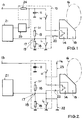
- an output circuit 10 of a safety system has an ignition or release capacitor 11, one connection of which is connected to ground via a charging resistor 24 to a supply voltage input 13 and a series circuit comprising a first switch H, a release device 14 and a second switch L. .
- the other connection of the capacitor 11 is directly to ground.
- a voltage divider 17, the resistors of which are in series between a fixed voltage, for example 5 V, and ground, is provided with its center tap 19 with a line 20 leading to the triggering device 14 and with an input of a test circuit integrated in particular in a triggering circuit or electronics. and evaluation circuit 21 connected, so that after checking the switches H, L while the security system is in standby, the line 20 can be checked continuously for connections.
- this capacitor terminal is connected to the test and evaluation circuit 21 via a converter circuit 25, which can be designed, for example, as a voltage divider.
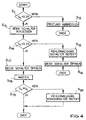
- the corresponding test routine is started immediately after the safety system is switched on.
- the start of the test routine - as shown in FIG. 4 - it is checked in step S11 whether the capacitor voltage U K is less than a predetermined value, for example 0.3 V. If this is not the case because the trigger capacitor 11 has not yet been completely discharged or has already been charged to a higher level, the test is terminated in step S12. The test routine is then ended. If, as expected, the capacitor voltage U K is smaller than the predetermined value, both switches H, L are closed in step S13. The capacitor voltage U K is then measured again in step S14 and compared with a second value, which may be 0.2 V, for example.
- a predetermined value for example 0.3 V
- a comparison value from the determined in step S11 capacitor voltage can be calculated, is decreased in the example, the value determined in step S11 of the capacitor voltage U K to 0.1 V.
- the checked capacitor voltage U K shows in step S14 that it has not decreased in the desired manner or is greater than an allowable limit value, e.g. B. can be set according to a maximum permissible test current for the triggering device, an error message is generated in step S15, which indicates that an error has occurred in the switches H, L. Then both switches are opened in step S16, in order to then end the test routine.
- step S14 If it is determined in step S14 that the capacitor voltage has dropped in the desired manner, both switches are then opened again in step S17 and a waiting time is started in step S18, after which the capacitor voltage U K with the target voltage has expired in step S19 U S is compared. If the comparison of step S19 shows that the capacitor voltage U K is approximately equal to the target voltage U S , the test routine for testing the output circuit, in particular for testing the switches H, L, is ended. However, if the capacitor voltage U K has not reached the required level after the waiting time from step S18, an error message is output in step S20, which indicates that the trigger capacitor 11 or its charging circuit is defective.
- switches H, L are checked immediately after the safety system is switched on, at a point in time at which the capacitor voltage U K has not yet exceeded a sufficiently small value and since the charging current for the tripping capacitor 11 is limited to a value by means of the charging resistor 24 , which ensures that when switches H, L are closed and the discharge capacitor 11 is practically uncharged, the current through the release device 14 is less than the permissible test current for the release device 14, both switches H, L can be tested simultaneously, with sporadically occurring ground faults in the off Line 20 and trigger device 14 formed ignition or trigger circuit can not lead to false triggering.
- Another advantage of the method according to the invention is that even in security systems which have only one switch in the output circuit 10, the functionality of this one switch can be checked simply and reliably.
Landscapes
- Engineering & Computer Science (AREA)
- Physics & Mathematics (AREA)
- General Physics & Mathematics (AREA)
- Automation & Control Theory (AREA)
- Mechanical Engineering (AREA)
- Air Bags (AREA)
- Keying Circuit Devices (AREA)
- Driving Mechanisms And Operating Circuits Of Arc-Extinguishing High-Tension Switches (AREA)
Abstract
Description
Die Erfindung betrifft ein Verfahren zum Überprüfen der Funktionsfähigkeit eines Ausgangsschaltkreises einer Auslöseschaltung eines Sicherheitssystems nach dem Oberbegriff des Patentanspruchs 1.The invention relates to a method for checking the functionality of an output circuit of a trigger circuit of a security system according to the preamble of patent claim 1.
Bei Sicherheitssystemen, insbesondere bei Sicherheitssystemen in Kraftfahrzeugen, die personenschützende Mittel, wie Airbags, Gurtstraffer und dergleichen umfassen, ist eine sehr hohe Systemzuverlässigkeit erforderlich. Insbesondere bei sicherheitskritischen Moduleinheiten wird verlangt, daß diese stets funktionsbereit sind und daß, falls doch ein Fehler auftritt, dieser sofort angezeigt wird, damit sich der Benutzer eines Fahrzeugs, der auf die Funktionsfähigkeit des Sicherheitssystems vertraut, sich nicht in einer Scheinsicherheit wiegt, sondern umgehend für eine Überprüfung und Instandsetzung des Sicherheitssystems sorgen kann.A very high level of system reliability is required in the case of safety systems, in particular in the case of safety systems in motor vehicles, which comprise personal protection means, such as airbags, belt tensioners and the like. In particular in the case of safety-critical module units, it is required that they are always ready for operation and that, if an error does occur, it is displayed immediately so that the user of a vehicle who trusts the functionality of the safety system does not weigh himself in apparent safety, but immediately can ensure that the safety system is checked and repaired.
Bei Airbag-/oder Gurtstraffersystemen werden daher elektrische und/oder elektronische Komponenten des Systems während einer von der Systemelektronik durchgeführten Eigendiagnose auf ihre Funktionsfähigkeit hin überprüft. Bei einem herkömmlichen Airbagsystem weist - wie Figur 2 zeigt - ein als Endstufe dienender Ausgangsschaltkreis 10 einen Zünd- oder Auslösekondensator 11 auf, der mit seinem einen Anschluß an einen Versorgungsspannungseingang 13 und mit seinem anderen Anschluß an Masse angeschlossen ist. Der mit dem Versorgungsspannungseingang 13 verbundene Anschluß des Auslösekondensators 11 ist über einen ersten Schalter H, eine Auslöseeinrichtung, zum Beispiel eine Zündpille, und einen zweiten Schalter L mit Masse verbunden, so daß, wenn der erste und der zweite Schalter H bzw. L geschlossen werden, ein Auslösestrom durch die Auslöseeinrichtung 14 fließt. Die Auslöseeinrichtung 14 setzt daraufhin eine Betätigungseinrichtung 15, zum Beispiel einen Gasgenerator, in Gang, die im Falle eines Airbagsystems einen Airbag 16 aufbläst.In airbag and / or belt tensioner systems, electrical and / or electronic components of the system are therefore checked for their functionality during a self-diagnosis carried out by the system electronics. In a conventional airbag system, as shown in FIG. 2, an
Für die Eigendiagnose ist im Ausgangsschaltkreis 10 ein Spannungsteiler 17 vorgesehen, dessen Widerstände 18 in Reihe zwischen einer vorgegebenen Spannung von beispielsweise 5 V und Masse liegen. Ein Mittelabgriff 19 des Spannungsteilers 17 ist einerseits mit einer zwischen den Schaltern H und L liegenden, zur Auslöseeinrichtung 14 führenden Leitung 20 und andererseits mit einem Eingang einer Prüf- u. Auswerteschaltung 21 verbunden. Die Prüf- u. Auswerteschaltung 21 ist dabei Bestandteil einer Auslöseschaltung oder Auslöseelektronik und kann beispielsweise in einem Mikroprozessor integriert sein.For self-diagnosis, a
Die Widerstände 18 des Spannungsteilers 17 sind so ausgelegt, daß eine Spannung Uz am Mittelabgriff 19 einen definierten Wert, z. B. 2 V, besitzt, solange die Leitung 20 auf einem schwebenden Potential liegt. Da die Leitung 20 normalerweise durch die Schalter H, L sowohl vom Auslösekondensator 11 als auch von Masse getrennt ist, liegt die Leitung 20 und die Auslöseeinrichtung 14 auf dem durch die Spannung Uz am Mittelabgriff 19 des Spannungsteilers 17 vorgegebenen Potential.The
Solange die Spannung Uz am Mittelabgriff 19 des Spannungsteilers 17 gleich dem vorgegebenen Wert, also beispielsweise gleich 2 V ist, gilt die beispielsweise in einem Kabelbaum angeordnete Leitung 20 als fehlerfrei. Es liegt also weder eine fehlerhafte Verbindung der Leitung 20 mit Masse (Masseschluß) noch eine fehlerhafte Verbindung der Leitung 20 mit einer die Batteriespannung führenden Leitung (Anliegeschluß gegen UB)vor.As long as the voltage Uz at the
Um in herkömmlicher Weise die beiden Schalter H und L auf ihre Funktionsfähigkeit hin zu überprüfen, wird - wie Figur 3 zeigt - nach dem Starten der Prüfroutine zunächst im Schritt S1 festgestellt, ob die Spannung Uz am Mittelabgriff 19 des Spannungsteilers 17 gleich dem vorgegebenen Wert, also gleich 2 V ist. Ist die Spannung Uz größer oder kleiner als der vorgegebene Wert 2 V, so liegt ein Anliegeschluß gegen die Batteriespannung UB bzw. gegen Masse vor und im Schritt S2 wird eine entsprechende Fehlermeldung erzeugt. Die Prüfroutine wird daraufhin abgebrochen.In order to check the functionality of the two switches H and L in the conventional way, as shown in FIG. 3, after starting the test routine it is first determined in step S1 whether the voltage Uz at the
Wird im Schritt S1 festgestellt, daß die Spannung Uz gleich dem vorgegebenen Wert ist, daß also die Leitung 20 als fehlerfrei bewertet wird, so wird im Schritt S3 der erste Schalter H geschlossen. Im Schritt S4 wird überprüft, ob die Spannung Uz größer als der vorgegebene Wert 2 V ist. Ist die Spannung Uz nicht angestiegen, so hat der Schalter H nicht einwandfrei geschlossen und im Schritt S5 wird eine entsprechende Fehlermeldung erzeugt. Wurde im Schritt S4 ein Anstieg der Spannung Uz und damit die einwandfreie Funktion des ersten Schalters H festgestellt, so wird im folgenden Schritt S6 der erste Schalter H wieder geöffnet. Dies erfolgt auch falls trotz einer Fehlermeldung in Schritt S5 die Prüfung des zweiten Schalters durchgeführt werden soll.If it is determined in step S1 that the voltage Uz is equal to the predetermined value, that is to say that the
Nach dem Öffnen des ersten Schalters H in Schritt S6 wird im Schritt S7 der zweite Schalter L geschlossen und im Schritt S8 wird geprüft, ob die Spannung Uz kleiner als der vorgegebene Wert 2 V ist. Trifft dies zu, so hat der zweite Schalter L fehlerfrei geschlossen. Somit kann nach dem Öffnen des Schalters L in Schritt S9 die Prüfroutine beendet werden. Wird bei der Überprüfung der Spannung Uz bei geschlossenem zweiten Schalter L festgestellt, daß die Spannung nicht nahezu dem Massepotential entspricht, so wird im Schritt S10 eine Fehlermeldung erzeugt, die anzeigt, daß der zweite Schalter L nicht einwandfrei schließt.After opening the first switch H in step S6, the second switch L is closed in step S7 and it is checked in step S8 whether the voltage Uz is less than the
Dieses herkömmliche Prüfverfahren arbeitet zwar relativ sicher, es birgt jedoch eine, wenn auch geringe Gefahr, daß es beim Testen der Schalter H, L zu einer Fehlauslösung der Auslöseeinrichtung 14 kommen kann. Trifft beispielsweise nach dem Überprüfen der Leitung 20 im Schritt S1 ein sporadischer Masseschluß auf, wie in Figur 2 durch eine gestrichelt dargestellte Leitung 22 angedeutet ist, so fließt beim Schließen des ersten Schalters H ein Auslösestrom obwohl der zweite Schalter L geöffnet ist. Umgekehrt kann bei einem sporadisch auftretenden Anliegeschluß gegen die Batteriespannung UB, der durch eine gestrichelt dargestellte Leitung 23 angedeutet ist, beim Schließen des zweiten Schalters L ein Auslösestrom durch die Auslöseeinrichtung 14 trotz geöffneten ersten Schalters H fließen. In beiden Fällen kommt es zu einer unerwünschten Auslösung des Airbags oder einer anderen personenschützenden Einrichtung.Although this conventional test method works relatively safely, there is a risk, albeit slight, that the
Davon ausgehend liegt der Erfindung die Aufgabe zugrunde, ein weiteres Verfahren zum Überprüfen der Funktionsfähigkeit eines Ausgangsschaltkreises einer Auslöseschaltung eines Sicherheitssystems bereitzustellen, bei dem insbesondere die Gefahr von Fehlauslösungen weiter verringert bzw. ausgeschlossen ist.Proceeding from this, the object of the invention is a further method for checking the functionality of a To provide the output circuit of a trigger circuit of a security system, in particular the risk of false tripping is further reduced or excluded.
Diese Aufgabe wird durch das Verfahren nach Anspruch 1 gelöst.This object is achieved by the method according to claim 1.
Erfindungsgemäß wird also die Überprüfung der Schalter im Ausgangsschaltkreis nicht zu einem beliebigen Zeitpunkt nach dem Einschalten des Sicherheitssystems sondern sofort nach dem Einschalten vorgenommen, bevor der Zünd- oder Auslösekondensator aufgeladen ist. Zur Überprüfung der Schalter, die die Auslöseeinrichtung auf einem schwebenden Potential halten, werden diese also geschlossen, solange die Spannung am Auslösekondensator noch so klein ist, daß der dadurch bewirkte Strom durch die Auslöseeinrichtung nicht ausreicht, um diese auszulösen. Hierbei wird insbesondere eine Fehlauslösung infolge eines sporadisch auftretenden oder ständig vorliegenden, den zwischen der Auslöseeinrichtung und Masse liegenden Schalter kurzschließenden Masseschlusses sicher verhindert.According to the invention, the switches in the output circuit are therefore not checked at any point in time after the safety system is switched on, but immediately after the switch on, before the ignition or release capacitor is charged. To check the switches that keep the triggering device at a floating potential, they are closed as long as the voltage at the triggering capacitor is still so low that the current caused by the triggering device is not sufficient to trigger it. In particular, false triggering due to a sporadic or permanent presence of a short to ground shorting the switch located between the triggering device and ground is reliably prevented.
Ein weiterer Vorteil des erfindungsgemäßen Verfahrens besteht darin, daß auch Ausgangsschaltkreise, die nur einen Schalter aufweisen, ohne die Gefahr einer Fehlauslösung auf die Funktionsfähigkeit des Schalters hin überprüft werden können.Another advantage of the method according to the invention is that even output circuits which have only one switch can be checked for the functionality of the switch without the risk of false triggering.
Die Sicherheit des erfindungsgemäßen Verfahrens läßt sich weiter erhöhen, indem vor der Überprüfung der Schalter festgestellt wird, ob die Kondensatorspannung einen höchstzulässigen Wert noch nicht überstiegen hat. Hierdurch lassen sich Fehlauslösungen beim Prüfen der Schalter vermeiden, die auftreten könnten, falls der Kondensator beim Einschalten des Sicherheitssystems noch nicht vollständig entladen ist oder falls infolge eines Fehlers im Ladeschaltkreis der Kondensator zu schnell geladen wurde.The safety of the method according to the invention can be further increased by ascertaining before the switches are checked whether the capacitor voltage has not yet exceeded a maximum permissible value. This avoids false triggers when testing the switches, which could occur if the capacitor is not yet fully discharged when the safety system is switched on or if the capacitor has been charged too quickly due to a fault in the charging circuit.
Zweckmäßigerweise wird die Kondensatorspannung bei geschlossenen Schaltern mit der Kondensatorspannung verglichen, die vor dem Schließen der Schalter vorlag, um eine Entladung des nur geringfügig aufgeladenen Auslösekondensators zu erfassen und um so die Leitfähigkeit der geschlossenen Schalter zu überprüfen. Zweckmäßigerweise kann hierzu ein Vergleichswert für die bei geschlossenen Schaltern vorliegende Kondensatorspannung vorgegeben werden, der insbesondere aus der Kondensatorspannung vor dem Schließen der Schalter ermittelt werden kann.The capacitor voltage in the case of closed switches is expediently compared with the capacitor voltage that existed before the switches were closed in order to detect a discharge of the trigger capacitor, which was only slightly charged, and in this way to check the conductivity of the closed switches. A comparative value for the capacitor voltage present when the switches are closed can expediently be specified for this purpose, which can be determined in particular from the capacitor voltage before the switches are closed.
Besonders vorteilhaft ist bei diesem Verfahren, daß auch die Überprüfung des Auslösekondensators auf einfache Weise in die entsprechende Prüfroutine integriert werden kann. Dazu wird insbesondere nach dem Öffnen der beiden Schalter oder, falls nur einer vorhanden ist, des Schalters und dem Ablauf einer Wartezeit die Kondensatorspannung erneut erfaßt und mit dem entsprechenden Sollwert verglichen.It is particularly advantageous with this method that the checking of the tripping capacitor can also be easily integrated into the corresponding test routine. For this purpose, in particular after the two switches have been opened or, if only one is present, the switch and the waiting time has elapsed, the capacitor voltage is detected again and compared with the corresponding setpoint.
Besonders zweckmäßig ist es, wenn der über die Auslöseeinrichtung fließende Strom auf einen Wert beschränkt wird, der kleiner als der zulässige Prüfstrom für die Auslöseeinrichtung ist.It is particularly expedient if the current flowing through the tripping device is limited to a value which is smaller than the permissible test current for the tripping device.
Die Erfindung wird im folgenden beispielsweise anhand der Zeichnung näher erläutert. In dieser zeigt:
- Fig. 1
- ein vereinfachtes schematisches Schaltbild eines Sicherheitssystems, das für die Überprüfung mit dem erfindungsgemäßen Verfahren geeignet ist,
- Fig. 2
- ein vereinfachtes schematisches Schaltbild eines herkömmlichen Sicherheitssystems,
- Fig. 3
- ein Flußdiagramm einer herkömmlichen Prüfroutine und
- Fig.4
- ein Flußdiagramm der Prüfroutine nach dem erfindungsgemäßen Verfahren.
- Fig. 1
- 1 shows a simplified schematic circuit diagram of a security system which is suitable for checking with the method according to the invention,
- Fig. 2
- a simplified schematic diagram of a conventional security system,
- Fig. 3
- a flowchart of a conventional test routine and
- Fig. 4
- a flowchart of the test routine according to the inventive method.
In den verschiedenen Figuren der Zeichnung sind einander entsprechende Teile mit gleichen Bezugszeichen versehen.Corresponding parts in the various figures of the drawing are provided with the same reference symbols.
Entsprechend Figur 1 weist ein Ausgangsschaltkreis 10 eines Sicherheitssystems einen Zünd- oder Auslösekondensator 11 auf, dessen einer Anschluß über einen Ladewiderstand 24 mit einem Versorgungsspannungseingang 13 sowie über eine Reihenschaltung aus einem ersten Schalter H, einer Auslöseeinrichtung 14 und einem zweiten Schalter L mit Masse verbunden ist. Der andere Anschluß des Kondensators 11 liegt unmittelbar an Masse. Ein Spannungsteiler 17, dessen Widerstände in Reihe zwischen einer festen Spannung, zum Beispiel 5 V, und Masse liegen, ist mit seinem Mittelabgriff 19 mit einer zur Auslöseeinrichtung 14 führenden Leitung 20 und mit einem Eingang einer insbesondere in einer Auslöseschaltung oder -elektronik integrierten Prüf- und Auswerteschaltung 21 verbunden, so daß nach dem Überprüfen der Schalter H, L, während das Sicherheitssystem in Bereitschaft ist, die Leitung 20 ständig auf Anliegeschlüsse überprüft werden kann.According to FIG. 1, an
Um den Ladezustand des Auslösekondensators 11, also die am ersten Anschluß des Auslösekondensators 11 vorliegende Spannung erfassen zu können, ist dieser Kondensatoranschluß über eine Wandlerschaltung 25, die beispielsweise als Spannungsteiler ausgebildet sein kann, mit der Prüf- und Auswerteschaltung 21 verbunden.In order to be able to detect the state of charge of the
Zum Überprüfen der Funktionsfähigkeit des Ausgangsschaltkreises 10 wird unmittelbar nach dem Einschalten des Sicherheitssystems die entsprechende Prüfroutine gestartet. Nach dem Start der Prüfroutine wird - wie Figur 4 zeigt - im Schritt S11 überprüft, ob die Kondensatorspannung UK kleiner als ein vorgegebener Wert, beispielsweise 0,3 V ist. Ist dies nicht der Fall, weil der Auslösekondensator 11 noch nicht vollständig entladen war oder bereits höher aufgeladen ist, wird im Schritt S12 die Prüfung abgebrochen. Anschließend wird die Prüfroutine beendet. Ist die Kondensatorspannung UK wie erwartet kleiner als der vorgegebene Wert, werden im Schritt S13 beide Schalter H, L geschlossen. Anschließend wird im Schritt S14 die Kondensatorspannung UK erneut gemessen und mit einem zweiten Wert verglichen, der beispielsweise 0,2 V sein kann. Anstelle eines fest vorgegebenen Vergleichswertes für die Überpüfung der Kondensatorspannung UK im Schritt S14 kann auch ein Vergleichswert aus der im Schritt S11 festgestellten Kondensatorspannung ermittelt werden, in dem beispielsweise der im Schritt S11 ermittelte Wert der Kondensatorspannung UK um 0,1 V verringert wird. Zeigt die überprüfte Kondensatorspannung UK im Schritt S14, daß diese nicht in der gewünschten Weise gesunken oder größer als ein erlaubter Grenzwert, der z. B. entsprechend einem maximal zulässigen Prüfstrom für die Auslöseeinrichtung festgelegt sein kann, ist, wird im Schritt S15 eine Fehlermeldung erzeugt, die anzeigt, daß ein Fehler in den Schaltern H, L aufgetreten ist. Anschließend werden im Schritt S16 beide Schalter geöffnet, um dann die Prüfroutine zu beenden.To check the functionality of the
Wird im Schritt S14 festgestellt, daß die Kondensatorspannung in der gewünschten Weise abgesunken ist, werden anschließend im Schritt S17 beide Schalter wieder geöffnet und es wird im Schritt S18 eine Wartezeit gestartet, nach deren Ablauf im Schritt S19 die Kondensatorspannung UK mit der Sollspannung US verglichen wird. Zeigt der Vergleich von Schritt S19, daß die Kondensatorspannung UK ungefähr gleich der Sollspannung US ist, so wird die Prüfroutine zum Prüfen des Ausgangsschaltkreises insbesondere zum Prüfen der Schalter H, L beendet. Hat jedoch die Kondensatorspannung UK nach Ablauf der Wartezeit von Schritt S18 nicht die erforderliche Höhe erreicht, so wird im Schritt S20 eine Fehlermeldung ausgegeben, die anzeigt, daß der Auslösekondensator 11 oder dessen Ladeschaltung defekt ist.If it is determined in step S14 that the capacitor voltage has dropped in the desired manner, both switches are then opened again in step S17 and a waiting time is started in step S18, after which the capacitor voltage U K with the target voltage has expired in step S19 U S is compared. If the comparison of step S19 shows that the capacitor voltage U K is approximately equal to the target voltage U S , the test routine for testing the output circuit, in particular for testing the switches H, L, is ended. However, if the capacitor voltage U K has not reached the required level after the waiting time from step S18, an error message is output in step S20, which indicates that the
Da die Überprüfung der Schalter H, L sofort nach dem Einschalten des Sicherheitssystems zu einem Zeitpunkt erfolgt, zu dem die Kondensatorspannung UK einen genügend kleinen Wert noch nicht überschritten hat und da der Ladestrom für den Auslösekondensator 11 mittels des Ladewiderstandes 24 auf einen Wert begrenzt ist, der sicherstellt, daß bei geschlossenen Schaltern H, L und praktisch ungeladenem Auslösekondensator 11 der Strom über die Auslöseeinrichtung 14 kleiner als der zulässige Prüfstrom für die Auslöseeinrichtung 14 ist, können beide Schalter H, L gleichzeitig geprüft werden, wobei auch sporadisch auftretende Masseschlüsse im aus Leitung 20 und Auslöseeinrichtung 14 gebildeten Zünd- oder Auslösekreis nicht zu einer Fehlauslösung führen können. Ein weiterer Vorteil des erfindungsgemäßen Verfahrens besteht darin, daß auch bei Sicherheitssystemen, die im Ausgangsschaltkreis 10 nur einen Schalter aufweisen, die Funktionsfähigkeit dieses einen Schalters einfach und zuverlässig überprüft werden kann.Since the switches H, L are checked immediately after the safety system is switched on, at a point in time at which the capacitor voltage U K has not yet exceeded a sufficiently small value and since the charging current for the tripping
Claims (9)
dadurch gekennzeichnet,
daß sofort nach dem Einschalten des Sicherheitssystems der oder die Schalter (H, L) überprüft werden, bevor der Auslösekondensator (11) auf seine Sollspannung (US) aufgeladen wird.Method for checking the functionality of an output circuit of a trigger circuit of a security system, the output circuit having at least one switch which switches a trigger current from a trigger capacitor to a trigger device,
characterized,
that the switch or switches (H, L) are checked immediately after the safety system is switched on before the tripping capacitor (11) is charged to its desired voltage (U S ).
dadurch gekennzeichnet, daß vor der Überprüfung des oder der Schalter (H, L) die Kondensatorspannung (UK) erfaßt und mit einem ersten, vorgegebenen Wert verglichen wird, und daß die Überprüfung des oder der Schalter (H, L) nur durchgeführt wird, wenn die Kondensatorspannung (UK) kleiner als der vorgegebene Wert ist.Method according to claim 1,
characterized in that before the check of the switch or switches (H, L) the capacitor voltage (U K ) is detected and compared with a first, predetermined value, and that the check of the switch or switches (H, L) is only carried out, if the capacitor voltage (U K ) is less than the specified value.
dadurch gekennzeichnet, daß der oder die Schalter (H, L) zur Überprüfung geschlossen werden und daß nach dem Schließen des oder der Schalter (H, L) die Kondensatorspannung (UK) erneut erfaßt und mit einem zweiten Wert verglichen wird, der nicht größer als ein erlaubter Grenzwert oder kleiner ist, als die Kondensatorspannung (UK) vor dem Schließen des oder der Schalter (H, L).The method of claim 1 or 2,
characterized in that the switch or switches (H, L) are closed for checking and in that after the switch or switches (H, L) is closed the capacitor voltage (U K ) is detected again and compared with a second value which is not greater than a permitted limit or less than the capacitor voltage (U K ) before the switch or switches (H, L) is closed.
dadurch gekennzeichnet, daß der zweite Wert vorgegeben ist.Method according to claim 3,
characterized in that the second value is predetermined.
dadurch gekennzeichnet, daß der zweite Wert aus der Kondensatorspannung (UK) vor dem Schließen des oder der Schalter (H, L) ermittelt wird.Method according to claim 3,
characterized in that the second value is determined from the capacitor voltage (U K ) before the switch or switches (H, L) is closed.
dadurch gekennzeichnet, daß nach der Überprüfung des oder der Schalter (H, L) die Kondensatorspannung (UK) erneut erfaßt und mit einem dritten Wert verglichen wird.Method according to one of claims 1 to 5,
characterized in that after checking the switch or switches (H, L) the capacitor voltage (U K ) is detected again and compared with a third value.
dadurch gekennzeichnet, daß die Kondensatorspannung (UK) nach der Überprüfung des oder der Schalter (H, L) erst erfaßt wird, wenn eine vorgegebene Zeit abgelaufen ist.Method according to claim 6,
characterized in that the capacitor voltage (U K ) is only detected after checking the switch or switches (H, L) when a predetermined time has elapsed.
dadurch gekennzeichnet, daß die nach der Überprüfung des oder der Schalter (H, L) erfaßte Kondensatorspannung (UK) mit dem Sollwert (US) der Kondensatorspannung verglichen wird.Method according to claim 6 or 7,
characterized in that the capacitor voltage (U K ) detected after checking the switch or switches (H, L) is compared with the desired value (U S ) of the capacitor voltage.
dadurch gekennzeichnet, daß der über den oder die geschlossenen Schalter (H, L) während der Überprüfung zur Auslöseeinrichtung (14) fließende Strom auf einen Wert beschränkt ist, der kleiner als der zulässige Prüfstrom für die Auslöseeinrichtung (14) ist.Method according to one of the preceding claims,
characterized in that the current flowing through the switch or switches (H, L) during the check to the trip device (14) is limited to a value which is less than the permissible test current for the trip device (14).
Applications Claiming Priority (2)
| Application Number | Priority Date | Filing Date | Title |
|---|---|---|---|
| DE19619118A DE19619118C1 (en) | 1996-05-11 | 1996-05-11 | Method for checking the functionality of an output circuit of a trigger circuit of a security system |
| DE19619118 | 1996-05-11 |
Publications (2)
| Publication Number | Publication Date |
|---|---|
| EP0806323A1 true EP0806323A1 (en) | 1997-11-12 |
| EP0806323B1 EP0806323B1 (en) | 1999-02-24 |
Family
ID=7794097
Family Applications (1)
| Application Number | Title | Priority Date | Filing Date |
|---|---|---|---|
| EP97107342A Expired - Lifetime EP0806323B1 (en) | 1996-05-11 | 1997-05-03 | Method of testing the functioning of an output stage of a triggering circuit of a safety device |
Country Status (3)
| Country | Link |
|---|---|
| EP (1) | EP0806323B1 (en) |
| DE (2) | DE19619118C1 (en) |
| ES (1) | ES2130862T3 (en) |
Cited By (3)
| Publication number | Priority date | Publication date | Assignee | Title |
|---|---|---|---|---|
| EP0947397A3 (en) * | 1998-04-04 | 2000-04-12 | DaimlerChrysler AG | Method for checking the operation of a passenger protection system as well a checking circuit to carry out the method |
| EP0979761A3 (en) * | 1998-08-10 | 2000-10-25 | Breed Automotive Technology, Inc. | Controller for a seatbelt tightener |
| EP0999956B1 (en) * | 1997-07-29 | 2002-03-27 | Siemens Aktiengesellschaft | System and method for testing a circuit device for controlling an automobile passenger protection mechanism |
Families Citing this family (2)
| Publication number | Priority date | Publication date | Assignee | Title |
|---|---|---|---|---|
| DE19922818A1 (en) * | 1999-05-19 | 2000-11-23 | Nokia Mobile Phones Ltd | Checking an evaluation circuit, involves checking for correct switch or button contacting, and switching input buffer to active state during interval for which output buffer is active |
| DE10147884A1 (en) * | 2001-09-28 | 2003-04-24 | Infineon Technologies Ag | Control device for passenger restraint of automobile passenger restraint system provides controlled operation of switches providing operating voltage for detonation capsule and shunt switch for latter |
Citations (5)
| Publication number | Priority date | Publication date | Assignee | Title |
|---|---|---|---|---|
| DE3920713A1 (en) * | 1989-06-24 | 1991-01-10 | Bosch Gmbh Robert | PASSENGER SAFETY DEVICE FOR VEHICLES |
| US5134306A (en) * | 1988-09-09 | 1992-07-28 | Robert Bosch Gmbh | Detonation circuit for a vehicle air bag |
| US5176214A (en) * | 1989-07-08 | 1993-01-05 | Robert Bosch Gmbh | Safety system for motor-vehicle occupants |
| EP0590180A1 (en) * | 1992-09-29 | 1994-04-06 | Siemens Aktiengesellschaft | Measure device for testing the earth connections of a control circuit, for example control circuit of an airbag system of a vehicle |
| US5389822A (en) * | 1990-05-23 | 1995-02-14 | Messerschmitt-Bolkow-Blohm Gmbh | Triggering circuit for a safety device in motor vehicles |
Family Cites Families (2)
| Publication number | Priority date | Publication date | Assignee | Title |
|---|---|---|---|---|
| JPH01274628A (en) * | 1988-04-25 | 1989-11-02 | Nippon Denso Co Ltd | Abnormality judging device for crew protection device |
| DE4220904A1 (en) * | 1992-06-25 | 1994-01-05 | Messerschmitt Boelkow Blohm | Testing mechanically operated switch in vehicle airbag passenger safety system - applying positive or negative voltage to end of test coil and checking for voltage change at other to sense fault caused by vibration in soldered connection on circuit board. |
-
1996
- 1996-05-11 DE DE19619118A patent/DE19619118C1/en not_active Expired - Fee Related
-
1997
- 1997-05-03 EP EP97107342A patent/EP0806323B1/en not_active Expired - Lifetime
- 1997-05-03 ES ES97107342T patent/ES2130862T3/en not_active Expired - Lifetime
- 1997-05-03 DE DE59700092T patent/DE59700092D1/en not_active Expired - Lifetime
Patent Citations (5)
| Publication number | Priority date | Publication date | Assignee | Title |
|---|---|---|---|---|
| US5134306A (en) * | 1988-09-09 | 1992-07-28 | Robert Bosch Gmbh | Detonation circuit for a vehicle air bag |
| DE3920713A1 (en) * | 1989-06-24 | 1991-01-10 | Bosch Gmbh Robert | PASSENGER SAFETY DEVICE FOR VEHICLES |
| US5176214A (en) * | 1989-07-08 | 1993-01-05 | Robert Bosch Gmbh | Safety system for motor-vehicle occupants |
| US5389822A (en) * | 1990-05-23 | 1995-02-14 | Messerschmitt-Bolkow-Blohm Gmbh | Triggering circuit for a safety device in motor vehicles |
| EP0590180A1 (en) * | 1992-09-29 | 1994-04-06 | Siemens Aktiengesellschaft | Measure device for testing the earth connections of a control circuit, for example control circuit of an airbag system of a vehicle |
Cited By (4)
| Publication number | Priority date | Publication date | Assignee | Title |
|---|---|---|---|---|
| EP0999956B1 (en) * | 1997-07-29 | 2002-03-27 | Siemens Aktiengesellschaft | System and method for testing a circuit device for controlling an automobile passenger protection mechanism |
| EP0947397A3 (en) * | 1998-04-04 | 2000-04-12 | DaimlerChrysler AG | Method for checking the operation of a passenger protection system as well a checking circuit to carry out the method |
| US6218739B1 (en) | 1998-04-04 | 2001-04-17 | Daimlerchrysler Ag | Procedure for the functional testing of a vehicle occupant protection system as well as a test circuit for implementing the procedure |
| EP0979761A3 (en) * | 1998-08-10 | 2000-10-25 | Breed Automotive Technology, Inc. | Controller for a seatbelt tightener |
Also Published As
| Publication number | Publication date |
|---|---|
| ES2130862T3 (en) | 1999-07-01 |
| DE59700092D1 (en) | 1999-04-01 |
| DE19619118C1 (en) | 1997-10-02 |
| EP0806323B1 (en) | 1999-02-24 |
Similar Documents
| Publication | Publication Date | Title |
|---|---|---|
| DE69100137T2 (en) | Means for detecting the presence of an abnormality in a vehicle occupant protection system. | |
| DE3913628C2 (en) | Device for determining the presence of an irregularity in a vehicle user protection system | |
| EP0301442B1 (en) | Circuit for checking the leads to a switch or a sensor | |
| DE4432444C2 (en) | The vehicle occupant protection system | |
| EP0478564B1 (en) | Safety device for vehicle passengers | |
| EP0691244A2 (en) | Test method for a passive safety device in motor vehicles | |
| DE2851333A1 (en) | TEST CIRCUIT FOR THE RELEASE DEVICE OF A SAFETY DEVICE THAT PROTECTS THE INSURANCE OF A VEHICLE DURING AN ACCIDENT | |
| DE19950008A1 (en) | Controlling and adjusting switching position of switch connection between electric outputs of fuel cell in mobile system, and mains network insulated in mobile system | |
| DE3400533C2 (en) | Triggering device for safety devices in vehicles | |
| EP0781216A1 (en) | Electronic safety device for motor vehicle passengers | |
| DE3506487C2 (en) | Power supply device for an occupant protection device in a vehicle | |
| EP0629161B1 (en) | Triggering circuit for a crash-sensor-controlled protective system in a vehicle | |
| EP0515977A2 (en) | Electronic ballast for high pressure discharge lamps used in automotive applications | |
| DE102004057694A1 (en) | Vehicle electrical system with higher voltage has switch opening conditions as voltages across resistances between first and second lines and earth, where both lines connect corresponding connections of battery and inverter and/or generator | |
| DE102018204968A1 (en) | Method and device for operating a motor vehicle | |
| EP0961383A1 (en) | Method and device for testing the capacity of a storage capacitor in a passenger safety system | |
| EP0482015B1 (en) | Safety system for vehicle occupants | |
| EP0806323B1 (en) | Method of testing the functioning of an output stage of a triggering circuit of a safety device | |
| WO1991005680A1 (en) | Circuit for triggering a vehicle passenger safety system | |
| DE3627239A1 (en) | CIRCUIT FOR CONTROLLING AND MONITORING IGNITION CIRCLES | |
| EP0732793B1 (en) | Circuit device, particularly for safety critical systems in vehicles used for transporting people | |
| DE19749856B4 (en) | Method and ignition circuit for triggering an occupant protection system | |
| EP0980005B1 (en) | Method and circuit for functional testing of an ignition circuit from a passenger safety system | |
| DE19819124A1 (en) | Control apparatus to release detonator of vehicle occupant protection device | |
| DE102005048239B3 (en) | Testing arrangement for switching device which is provided for the control of person protection means of vehicle, has power level which can be controlled and arranged parallel to a series connection from an igniting element |
Legal Events
| Date | Code | Title | Description |
|---|---|---|---|
| PUAI | Public reference made under article 153(3) epc to a published international application that has entered the european phase |
Free format text: ORIGINAL CODE: 0009012 |
|
| AK | Designated contracting states |
Kind code of ref document: A1 Designated state(s): DE ES FR GB IT SE |
|
| 17P | Request for examination filed |
Effective date: 19971014 |
|
| 17Q | First examination report despatched |
Effective date: 19971218 |
|
| GRAG | Despatch of communication of intention to grant |
Free format text: ORIGINAL CODE: EPIDOS AGRA |
|
| GRAG | Despatch of communication of intention to grant |
Free format text: ORIGINAL CODE: EPIDOS AGRA |
|
| GRAH | Despatch of communication of intention to grant a patent |
Free format text: ORIGINAL CODE: EPIDOS IGRA |
|
| GRAH | Despatch of communication of intention to grant a patent |
Free format text: ORIGINAL CODE: EPIDOS IGRA |
|
| GRAA | (expected) grant |
Free format text: ORIGINAL CODE: 0009210 |
|
| AK | Designated contracting states |
Kind code of ref document: B1 Designated state(s): DE ES FR GB IT SE |
|
| ITF | It: translation for a ep patent filed | ||
| GBT | Gb: translation of ep patent filed (gb section 77(6)(a)/1977) |
Effective date: 19990224 |
|
| REF | Corresponds to: |
Ref document number: 59700092 Country of ref document: DE Date of ref document: 19990401 |
|
| ET | Fr: translation filed | ||
| REG | Reference to a national code |
Ref country code: ES Ref legal event code: FG2A Ref document number: 2130862 Country of ref document: ES Kind code of ref document: T3 |
|
| PLBE | No opposition filed within time limit |
Free format text: ORIGINAL CODE: 0009261 |
|
| STAA | Information on the status of an ep patent application or granted ep patent |
Free format text: STATUS: NO OPPOSITION FILED WITHIN TIME LIMIT |
|
| 26N | No opposition filed | ||
| REG | Reference to a national code |
Ref country code: GB Ref legal event code: IF02 |
|
| PGFP | Annual fee paid to national office [announced via postgrant information from national office to epo] |
Ref country code: DE Payment date: 20120523 Year of fee payment: 16 |
|
| PGFP | Annual fee paid to national office [announced via postgrant information from national office to epo] |
Ref country code: SE Payment date: 20120522 Year of fee payment: 16 Ref country code: GB Payment date: 20120522 Year of fee payment: 16 Ref country code: FR Payment date: 20120601 Year of fee payment: 16 |
|
| PGFP | Annual fee paid to national office [announced via postgrant information from national office to epo] |
Ref country code: IT Payment date: 20120531 Year of fee payment: 16 |
|
| PGFP | Annual fee paid to national office [announced via postgrant information from national office to epo] |
Ref country code: ES Payment date: 20120525 Year of fee payment: 16 |
|
| REG | Reference to a national code |
Ref country code: SE Ref legal event code: EUG |
|
| GBPC | Gb: european patent ceased through non-payment of renewal fee |
Effective date: 20130503 |
|
| PG25 | Lapsed in a contracting state [announced via postgrant information from national office to epo] |
Ref country code: SE Free format text: LAPSE BECAUSE OF NON-PAYMENT OF DUE FEES Effective date: 20130504 Ref country code: DE Free format text: LAPSE BECAUSE OF NON-PAYMENT OF DUE FEES Effective date: 20131203 |
|
| PG25 | Lapsed in a contracting state [announced via postgrant information from national office to epo] |
Ref country code: IT Free format text: LAPSE BECAUSE OF NON-PAYMENT OF DUE FEES Effective date: 20130503 |
|
| REG | Reference to a national code |
Ref country code: DE Ref legal event code: R119 Ref document number: 59700092 Country of ref document: DE Effective date: 20131203 |
|
| REG | Reference to a national code |
Ref country code: FR Ref legal event code: ST Effective date: 20140131 |
|
| PG25 | Lapsed in a contracting state [announced via postgrant information from national office to epo] |
Ref country code: GB Free format text: LAPSE BECAUSE OF NON-PAYMENT OF DUE FEES Effective date: 20130503 |
|
| PG25 | Lapsed in a contracting state [announced via postgrant information from national office to epo] |
Ref country code: FR Free format text: LAPSE BECAUSE OF NON-PAYMENT OF DUE FEES Effective date: 20130531 |
|
| REG | Reference to a national code |
Ref country code: ES Ref legal event code: FD2A Effective date: 20140606 |
|
| PG25 | Lapsed in a contracting state [announced via postgrant information from national office to epo] |
Ref country code: ES Free format text: LAPSE BECAUSE OF NON-PAYMENT OF DUE FEES Effective date: 20130504 |