EP0515977A2 - Electronic ballast for high pressure discharge lamps used in automotive applications - Google Patents
Electronic ballast for high pressure discharge lamps used in automotive applications Download PDFInfo
- Publication number
- EP0515977A2 EP0515977A2 EP92108556A EP92108556A EP0515977A2 EP 0515977 A2 EP0515977 A2 EP 0515977A2 EP 92108556 A EP92108556 A EP 92108556A EP 92108556 A EP92108556 A EP 92108556A EP 0515977 A2 EP0515977 A2 EP 0515977A2
- Authority
- EP
- European Patent Office
- Prior art keywords
- voltage
- ballast
- converter
- ignition
- safety device
- Prior art date
- Legal status (The legal status is an assumption and is not a legal conclusion. Google has not performed a legal analysis and makes no representation as to the accuracy of the status listed.)
- Granted
Links
Images
Classifications
-
- H—ELECTRICITY
- H05—ELECTRIC TECHNIQUES NOT OTHERWISE PROVIDED FOR
- H05B—ELECTRIC HEATING; ELECTRIC LIGHT SOURCES NOT OTHERWISE PROVIDED FOR; CIRCUIT ARRANGEMENTS FOR ELECTRIC LIGHT SOURCES, IN GENERAL
- H05B41/00—Circuit arrangements or apparatus for igniting or operating discharge lamps
- H05B41/14—Circuit arrangements
- H05B41/26—Circuit arrangements in which the lamp is fed by power derived from dc by means of a converter, e.g. by high-voltage dc
- H05B41/28—Circuit arrangements in which the lamp is fed by power derived from dc by means of a converter, e.g. by high-voltage dc using static converters
- H05B41/288—Circuit arrangements in which the lamp is fed by power derived from dc by means of a converter, e.g. by high-voltage dc using static converters with semiconductor devices and specially adapted for lamps without preheating electrodes, e.g. for high-intensity discharge lamps, high-pressure mercury or sodium lamps or low-pressure sodium lamps
- H05B41/292—Arrangements for protecting lamps or circuits against abnormal operating conditions
- H05B41/2921—Arrangements for protecting lamps or circuits against abnormal operating conditions for protecting the circuit against abnormal operating conditions
-
- Y—GENERAL TAGGING OF NEW TECHNOLOGICAL DEVELOPMENTS; GENERAL TAGGING OF CROSS-SECTIONAL TECHNOLOGIES SPANNING OVER SEVERAL SECTIONS OF THE IPC; TECHNICAL SUBJECTS COVERED BY FORMER USPC CROSS-REFERENCE ART COLLECTIONS [XRACs] AND DIGESTS
- Y02—TECHNOLOGIES OR APPLICATIONS FOR MITIGATION OR ADAPTATION AGAINST CLIMATE CHANGE
- Y02B—CLIMATE CHANGE MITIGATION TECHNOLOGIES RELATED TO BUILDINGS, e.g. HOUSING, HOUSE APPLIANCES OR RELATED END-USER APPLICATIONS
- Y02B20/00—Energy efficient lighting technologies, e.g. halogen lamps or gas discharge lamps
-
- Y—GENERAL TAGGING OF NEW TECHNOLOGICAL DEVELOPMENTS; GENERAL TAGGING OF CROSS-SECTIONAL TECHNOLOGIES SPANNING OVER SEVERAL SECTIONS OF THE IPC; TECHNICAL SUBJECTS COVERED BY FORMER USPC CROSS-REFERENCE ART COLLECTIONS [XRACs] AND DIGESTS
- Y10—TECHNICAL SUBJECTS COVERED BY FORMER USPC
- Y10S—TECHNICAL SUBJECTS COVERED BY FORMER USPC CROSS-REFERENCE ART COLLECTIONS [XRACs] AND DIGESTS
- Y10S315/00—Electric lamp and discharge devices: systems
- Y10S315/07—Starting and control circuits for gas discharge lamp using transistors
Definitions
- a ballast is known from German patent DE 34 45 817 C2, which has a circuit arrangement for operating a high-pressure gas discharge lamp on a low-voltage DC voltage.
- the ballast has at least one voltage converter, which is connected to the vehicle battery and the vehicle ground.
- the at least one voltage converter generates a lamp supply voltage and / or an auxiliary ignition voltage and is electrically conductively connected to an ignition device for igniting and operating high-pressure gas discharge lamps.
- a supply voltage pre-regulator which has a DC / DC converter, is connected to the ignition device of an AC high-pressure gas discharge lamp via a transistor inverter, a rectifier and an LF rectangular inverter.
- the circuit arrangement also has monitoring electronics with which a deviation in the supply voltage from a predetermined window area can be detected and, in the event of such a deviation, the ballast switches off.
- the monitoring electronics also have reverse polarity protection.
- the use of the bridge switch (BS) can be dispensed with, when the high pressure gas discharge lamp (GDL) to be controlled is a direct current high pressure gas discharge lamp (GDL).
Abstract
Description
Die Erfindung betrifft ein Vorschaltgerät für Hochdruck-Gasentladungslampen in Kraftfahrzeugen, das aus einer Fahrzeugbatterie gespeist wird, wobei das Vorschaltgerät mindestens einen Spannungswandler aufweist, der mit der Fahrzeugbatterie und der Fahrzeugmasse verbunden ist, der eine Lampenversorgungsspannung und/oder eine Zündhilfsspannung erzeugt und elektrisch leitend mit einer Zündeinrichtung zum Zünden und Betreiben von Hochdruck-Gasentladungslampen verbunden ist.The invention relates to a ballast for high-pressure gas discharge lamps in motor vehicles, which is fed from a vehicle battery, the ballast having at least one voltage converter which is connected to the vehicle battery and the vehicle ground, which generates a lamp supply voltage and / or an auxiliary ignition voltage and is electrically conductive with an ignition device for igniting and operating high-pressure gas discharge lamps.
Aus der deutschen Patentschrift DE 34 45 817 C2 ist ein Vorschaltgerät bekannt, das eine Schaltungsanordnung zum Betrieb einer Hochdruck-Gasentladungslampe an einer Niedervolt-Gleichspannung aufweist. Das Vorschaltgerät weist dabei mindestens einen Spannungswandler auf, der mit der Fahrzeugbatterie und der Fahrzeugmasse verbunden ist. Der mindestens eine Spannungswandler erzeugt eine Lampenversorgungsspannung und/oder eine Zündhilfsspannung und ist elektrisch leitend mit einer Zündeinrichtung zum Zünden und Betreiben von Hochdruck-Gasentladungslampen verbunden. Bei dem hier gezeigten Ausführungsbeispiel, das sehr aufwendig und kostenintensiv ist, ist ein Speisespannungs-Vorregler, der einen DC/DC-Wandler aufweist, über einen Transistorwechselrichter, einen Gleichrichter und einen NF-Rechteckwechselrichter mit der Zündeinrichtung einer Wechselstrom-Hochdruck-Gasentladungslampe verbunden. Die Schaltungsanordnung weist zudem eine Überwachungselektronik auf, mit der ein Abweichen der Versorgungsspannung aus einem vorgegebenen Fensterbereich detektiert werden kann und bei einem derartigen Abweichen das Vorschaltgerät abschaltet. Zudem weist die Überwachungselektronik einen Verpolungsschutz auf.A ballast is known from German patent DE 34 45 817 C2, which has a circuit arrangement for operating a high-pressure gas discharge lamp on a low-voltage DC voltage. The ballast has at least one voltage converter, which is connected to the vehicle battery and the vehicle ground. The at least one voltage converter generates a lamp supply voltage and / or an auxiliary ignition voltage and is electrically conductively connected to an ignition device for igniting and operating high-pressure gas discharge lamps. In the exemplary embodiment shown here, which is very complex and cost-intensive, a supply voltage pre-regulator, which has a DC / DC converter, is connected to the ignition device of an AC high-pressure gas discharge lamp via a transistor inverter, a rectifier and an LF rectangular inverter. The circuit arrangement also has monitoring electronics with which a deviation in the supply voltage from a predetermined window area can be detected and, in the event of such a deviation, the ballast switches off. The monitoring electronics also have reverse polarity protection.
Bei dem Betrieb des Vorschaltgeräts weisen die Verbindungsleitungen zwischen den einzelnen Komponenten und insbesondere die Verbindungsleitungen zu dem Zündgerät hohe Spannungen auf, die für Personen, die diese Leitungen berühren, gefährlich werden können. Personen können z. B. bei dem Versuch, Reparaturarbeiten vorzunehmen, in Kontakt zu den Leitungen geraten oder aber auch mit diesen Leitungen in Kontakt geraten, wenn z. B. durch einen Unfall des Kraftfahrzeugs diese im Scheinwerferbereich oder in dem Motorraum des Kraftfahrzeugs frei gelegt worden sind. Bei der vorbekannten Schaltungsanordnung erweist sich dabei als nachteilig, daß Personen, die spannungsführende Teile des Vorschaltgerätes berühren, nicht gegen Spannungsschläge geschützt sind, so daß eine hohe Gefährdung für diese Personen besteht.When the ballast is in operation, the connecting lines between the individual components and in particular the connecting lines to the igniter have high voltages which can be dangerous for persons who touch these lines. People can e.g. B. when trying to carry out repair work, come into contact with the lines or also come into contact with these lines if, for. B. have been exposed by an accident of the motor vehicle in the headlight area or in the engine compartment of the motor vehicle. In the known circuit arrangement, it proves disadvantageous that people who touch live parts of the ballast are not protected against voltage surges, so that there is a high risk for these people.
Der Erfindung liegt die Aufgabe zugrunde, ein Vorschaltgerät für Hochdruck-Gasentladungslampen in Kraftfahrzeugen zu schaffen, bei dem Personen, die spannungsführende Teile des Vorschaltgerätes berühren, bestmöglich geschützt werden und bei dem das Vorschaltgerät bei dem Auftreten von Fehlern wie Kurzschlüssen oder Überströmen sicher geschützt wird.The invention has for its object to provide a ballast for high pressure gas discharge lamps in motor vehicles, in which people who touch live parts of the ballast are protected as well as possible and in which the ballast is safely protected in the event of errors such as short circuits or overcurrents.
Die Aufgabe wird erfindungsgemäß dadurch gelöst, daß die Lampenversorgungsspannung und/oder die Zündhilfsspannung durch den Spannungswandler von der Batteriespannung der Fahrzeugbatterie galvanisch getrennt erzeugt werden und daß das Bezugspotential der Zündhilfsspannung und/oder der Lampenversorgungsspannung über einen niederohmigen ersten Meßwiderstand mit der Fahrzeugmasse verbunden ist.The object is achieved in that the lamp supply voltage and / or the auxiliary ignition voltage are generated in an electrically isolated manner by the voltage converter from the battery voltage of the vehicle battery and in that the reference potential of the auxiliary ignition voltage and / or the lamp supply voltage is connected to the vehicle ground via a low-resistance first measuring resistor.
Es ist von Vorteil, daß die Lampenversorgungsspannung und/oder die Zündhilfsspannung durch den Spannungswandler von der Batteriespannung der Fahrzeugbatterie galvanisch getrennt erzeugt werden und daß das Bezugspotential der Zündhilfsspannung und/oder der Lampenversorgungsspannung über einen niederohmigen ersten Meßwiderstand mit der Fahrzeugmasse verbunden ist, weil somit auf einfache und kostengünstige Weise aufgrund des Spannungsabfalls an dem niederohmigen ersten Meßwiderstand, der mit dem Bezugspotential des Vorschaltgerätes verbunden ist, selbst minimale Fehlerströme gemessen und bestimmt werden können, die z. B. auftreten, wenn eine Person eines der spannungsführenden Teile des Vorschaltgerätes berührt.It is advantageous that the lamp supply voltage and / or the auxiliary ignition voltage by the voltage converter of the battery voltage of the vehicle battery are generated in an electrically isolated manner and that the reference potential of the auxiliary ignition voltage and / or the lamp supply voltage is connected to the vehicle ground via a low-resistance first measuring resistor, because it is thus simple and cost-effective because of the voltage drop across the low-resistance first measuring resistor that corresponds to the reference potential the ballast is connected, even minimal fault currents can be measured and determined, which, for. B. occur when a person touches one of the live parts of the ballast.
Eine derartige einfache und kostengünstige Fehlerstromerkennung kann eine hohe Sicherheit bei dem Betrieb von Vorschaltgeräten für Hochdruck-Gasentladungslampen in Kraftfahrzeugen bieten, wenn aus dem Spannungsabfall an dem niederohmigen ersten Meßwiderstand ein Fehlerstromsignal zum Abschalten des Vorschaltgerätes erzeugt wird. Durch die galvanische Trennung der Batteriespannung von den Ausgangsspannungen des Spannungswandlers wird dabei sichergestellt, daß über den niederohmigen ersten Meßwiderstand mit hoher Sicherheit geringe Fehlerströme erkannt werden können. Eine galvanische Trennung kann dabei durch Verwendung einer entsprechenden Transformatoranordnung erreicht werden.Such a simple and inexpensive fault current detection can offer a high level of security when operating ballasts for high-pressure gas discharge lamps in motor vehicles if a fault current signal for switching off the ballast is generated from the voltage drop across the low-resistance first measuring resistor. The galvanic isolation of the battery voltage from the output voltages of the voltage converter ensures that low fault currents can be detected with a high degree of certainty via the low-resistance first measuring resistor. Galvanic isolation can be achieved by using an appropriate transformer arrangement.
Es ist von Vorteil, daß der Meßwiderstand elektrisch leitend mit einer Sicherheitseinrichtung verbunden ist, daß die Sicherheitseinrichtung eine Fehlerstromermittlungseinrichtung aufweist, daß die Sicherheitseinrichtung eine Auswerte- und Schalteinrichtung aufweist, die ein Abschaltsignal erzeugt, wenn die Fehlerstromermittlungseinrichtung einen vorgegebenen Fehlerstrom ermittelt und daß die Sicherheitseinrichtung elektrisch leitend mit dem Spannungswandler verbunden ist, weil somit auf besonders einfache Weise bei dem Vorliegen eines Spannungsabfalls an dem niederohmigen ersten Meßwiderstand ein Fehlerstrom ermittelt werden kann und dieser ermittelte Fehlerstrom je nach Größe dazu verwendet werden kann, daß die Spannungsversorgung durch den Spannungswandler aufgrund des erzeugten Abschaltsignals unterbrochen wird und somit das gesamte Vorschaltgerät abgeschaltet wird, was zu einer großen Sicherheit, insbesondere für Personen führt, die spannungsführende Teile des Vorschaltgerätes berühren. Die Fehlerströme, die zu einem Abschalten des Vorschaltgeräts durch die Sicherheitseinrichtung führen, können dabei beispielhaft etwa eine Größenordnung von 20 bis 30 mA aufweisen. Je nach Anwendung können diese Werte auch großer oder kleiner sein.It is advantageous that the measuring resistor is connected in an electrically conductive manner to a safety device, that the safety device has a fault current detection device, that the safety device has an evaluation and switching device that generates a switch-off signal when the fault current detection device determines a predetermined fault current and that the safety device is electrical is conductively connected to the voltage converter because it is thus particularly simple when there is a voltage drop at the low-resistance first Measuring resistance a fault current can be determined and this determined fault current can be used depending on the size that the voltage supply through the voltage converter is interrupted due to the generated shutdown signal and thus the entire ballast is switched off, which leads to a high level of safety, especially for people who Touch live parts of the ballast. The fault currents which lead to the ballast being switched off by the safety device can, for example, have a magnitude of approximately 20 to 30 mA. Depending on the application, these values can also be larger or smaller.
Dadurch, daß in der Verbindung zwischen dem Spannungswandler und der Zündeinrichtung, die das Bezugspotential aufweist, ein zweiter Meßwiderstand angeordnet ist, ergibt sich auf einfache und kostengünstige Weise die Möglichkeit, den bei dem Betrieb der Hochdruck-Gasentladungslampe auftretenden Lampenstrom aufgrund des Spannungsabfalls an dem zweiten Meßwiderstand zu bestimmen.Because a second measuring resistor is arranged in the connection between the voltage converter and the ignition device, which has the reference potential, the possibility arises in a simple and inexpensive manner that the lamp current occurring during the operation of the high-pressure gas discharge lamp due to the voltage drop across the second Determine measuring resistance.
In diesem Zusammenhang erweist sich als besonders vorteilhaft, daß die Verbindung zwischen dem zweiten Meßwiderstand und der Zündeinrichtung elektrisch leitend mit der Sicherheitseinrichtung verbunden ist und daß die Sicherheitseinrichtung eine Lampenstromermittlungseinrichtung aufweist, die mit der Auswerte- und Schalteinrichtung verbunden ist, wodurch auf einfache und kostengünstige Weise der bei dem Betrieb der Hochdruck-Gasentladungslampe und auch bei dem Starten der Hochdruck-Gasentladungslampe auftretende Lampenstrom mit hoher Sicherheit bestimmt werden kann. Durch die Messung und Ermittlung des Lampenstroms können somit auch Fehler in dem Lampenstrom leicht und zuverlässig erkannt werden, die z. B. durch Kurzschlüsse zwischen den Leitungen entstehen können. Bei solchen Fehlern erzeugt die Auswerte- und Schalteinrichtung der Sicherheitseinrichtung ebenso wie bei dem Auftreten von Fehlerströmen ein Abschaltsignal, das dem Spannungswandler zugeführt wird und diesen und damit das gesamte Vorschaltgerät abschaltet, wodurch sich eine hohe Sicherheit bei dem Betrieb des Vorschaltgerätes ergibt.In this context, it has been found to be particularly advantageous that the connection between the second measuring resistor and the ignition device is electrically conductively connected to the safety device and that the safety device has a lamp current detection device which is connected to the evaluation and switching device, thereby making it simple and inexpensive the lamp current occurring during the operation of the high-pressure gas discharge lamp and also when the high-pressure gas discharge lamp is started can be determined with a high degree of certainty. By measuring and determining the lamp current, errors in the lamp current can thus be easily and reliably detected, which, for. B. can arise from short circuits between the lines. With such errors, the evaluation and Switching device of the safety device as well as a shutdown signal when fault currents occur, which is fed to the voltage converter and this and thus the entire ballast switches off, resulting in a high level of safety in the operation of the ballast.
Es ist von Vorteil, daß in der Verbindung zwischen dem Spannungswandler und der Zündeinrichtung, die die Zündhilfsspannung leitet, ein dritter Meßwiderstand angeordnet ist, weil somit auf einfache und kostengünstige Weise aufgrund des Spannungsabfalls an dem dritten Meßwiderstand der Zündstrom zuverlässig bestimmt werden kann.It is advantageous that a third measuring resistor is arranged in the connection between the voltage converter and the ignition device, which conducts the auxiliary ignition voltage, because the ignition current can thus be reliably determined in a simple and inexpensive manner due to the voltage drop across the third measuring resistor.
In diesem Zusammenhang ist es besonders vorteilhaft, daß die Verbindung zwischen dem dritten Meßwiderstand und der Zündeinrichtung mit der Sicherheitseinrichtung verbunden ist und daß die Sicherheitseinrichtung eine Zündstromermittlungseinrichtung aufweist, die mit der Auswerte- und Schalteinrichtung verbunden ist, weil somit auf einfache und kostengünstige Weise besonders zuverlässig der Zündstrom bei dem Starten der Hochdruck-Gasentladungslampe bestimmt werden kann, und bei Fehlern des Zündstroms, die z. B. durch Kurzschlüsse bedingt sein können, durch die Auswerte- und Schalteinrichtung ein Abschaltsignal erzeugt werden kann, das von der Sicherheitseinrichtung dem Spannungswandler zugeführt wird und zu einer Abschaltung des Spannungswandlers und damit des Zündgerätes führt, was eine hohe Sicherheit bei dem Betrieb des Vorschaltgerätes ergibt.In this context, it is particularly advantageous that the connection between the third measuring resistor and the ignition device is connected to the safety device and that the safety device has an ignition current detection device that is connected to the evaluation and switching device, because it is particularly reliable in a simple and inexpensive manner the ignition current can be determined when the high-pressure gas discharge lamp is started, and in the event of errors in the ignition current which, for. B. may be caused by short-circuits, a shutdown signal can be generated by the evaluation and switching device, which is fed from the safety device to the voltage converter and leads to a shutdown of the voltage converter and thus the ignitor, which results in a high level of safety in the operation of the ballast .
Es ist von Vorteil, daß der Spannungswandler ein DC/DC-Wandler mit galvanischer Trennung der Ein- und Ausgangsspannungen ist, daß der DC/DC-Wandler eine zweite Ausgangsklemme aufweist, an der die Lampenversorgungsspannung anliegt, daß der DC/DC-Wandler eine dritte Ausgangsklemme aufweist, an der die Zündhilfsspannung anliegt, daß der DC/DC-Wandler eine erste Ausgangsklemme aufweist, die das Bezugspotential für die Lampenversorgungsspannung und die Zündhilfsspannung aufweist und daß die erste Ausgangsklemme mit dem ersten Meßwiderstand und der Fehlerstromermittlungseinrichtung der Sicherheitseinrichtung verbunden ist, weil somit ein besonders einfach aufgebautes und kostengünstig herstellbares Vorschaltgerät zum Betreiben von Hochdruck-Gasentladungslampen vorliegt, bei dem schon geringe Berührungsströme, die aus dem gemessenen Spannungsabfall an dem ersten Meßwiderstand durch die Fehlerstromermittlungseinrichtung bestimmt werden, ein zuverlässiges Abschalten des Vorschaltgerätes bewirken.It is advantageous that the voltage converter is a DC / DC converter with electrical isolation of the input and output voltages, that the DC / DC converter has a second output terminal to which the lamp supply voltage is present, that the DC / DC converter is a has third output terminal, to which the auxiliary ignition voltage is present, that the DC / DC converter is a first Output terminal that has the reference potential for the lamp supply voltage and the auxiliary ignition voltage and that the first output terminal is connected to the first measuring resistor and the residual current detection device of the safety device, because thus a particularly simple and inexpensive ballast for operating high-pressure gas discharge lamps is available, in which Even small contact currents, which are determined from the measured voltage drop across the first measuring resistor by the residual current detection device, bring about a reliable shutdown of the ballast.
Dadurch, daß die zweite Ausgangsklemme mit einer Lampenspannungsermittlungseinrichtung der Sicherheitseinrichtung verbunden ist, kann auf einfache und kostengünstige Weise die Lampenspannung durch die Sicherheitseinrichtung auf Fehler überprüft und ein möglicher Kurzschluß erfaßt werden.Because the second output terminal is connected to a lamp voltage determination device of the safety device, the lamp voltage can be checked for errors by the safety device in a simple and inexpensive manner and a possible short circuit can be detected.
Dadurch, daß die dritte Ausgangsklemme mit einer Zündhilfsspannungsermittlungseinrichtung der Sicherheitseinrichtung verbunden ist, ergibt sich der Vorteil, daß die Zündhilfsspannung einfach und kostengünstig auf Fehler überprüft werden kann.The fact that the third output terminal is connected to an auxiliary ignition voltage determination device of the safety device results in the advantage that the auxiliary ignition voltage can be checked easily and inexpensively for errors.
Durch die Messung von Lampenspannung, Lampenstrom, Zündhilfsspannung und Zündstrom ergibt sich zudem der Vorteil, daß diese Meßwerte zum Regeln oder Steuern des Zündverhaltens und/oder des Betriebs der Hochdruck-Gasentladungslampe auf einfache Weise mitbenutzt werden können.The measurement of the lamp voltage, lamp current, auxiliary ignition voltage and ignition current also has the advantage that these measured values can be used in a simple manner for regulating or controlling the ignition behavior and / or the operation of the high-pressure gas discharge lamp.
Es ist von Vorteil, daß in der Verbindung zwischen dem DC/DC-Wandler und der Zündeinrichtung ein Wechselrichter angeordnet ist, weil somit auf einfache und kostengünstige Weise eine Wechselstrom-Hochdruck-Gasentladungslampe von dem Vorschaltgerät mit hoher Zuverlässigkeit betrieben werden kann.It is advantageous that an inverter is arranged in the connection between the DC / DC converter and the ignition device, because an AC high-pressure gas discharge lamp from is thus simple and inexpensive the ballast can be operated with high reliability.
Es ist von Vorteil, daß der Spannungswandler ein Wechselrichter ist, wodurch bei Verzicht auf die Verwendung eines DC/DC-Wandlers ein besonders einfacher Aufbau zum Betreiben einer Wechselstrom-Hochdruck-Gasentladungslampe erreicht wird.It is advantageous that the voltage converter is an inverter, whereby a particularly simple structure for operating an AC high-pressure gas discharge lamp is achieved when a DC / DC converter is not used.
Es ist von Vorteil, daß das von der Sicherheitseinrichtung erzeugte Abschaltsignal das gesamte Vorschaltgerät dauerhaft bis zum nächsten Einschaltversuch abschaltet, weil somit sichergestellt wird, daß bei dem Vorliegen eines vorgegebenen Fehlerstroms oder eines Fehlers in der Lampenspannung, in der Zündhilfsspannung, in dem Zündstrom oder in dem Lampenstrom jede Gefährdung von Personen durch spannungsführende Teile ausgeschlossen wird und zudem sichergestellt wird, daß Bauteile des Vorschaltgerätes, z. B. bei dem Vorliegen von Kurzschlüssen, nicht zerstört werden.It is advantageous that the switch-off signal generated by the safety device switches off the entire ballast permanently until the next switch-on attempt, because this ensures that if there is a predetermined fault current or a fault in the lamp voltage, in the auxiliary ignition voltage, in the ignition current or in the lamp current any danger to people from live parts is excluded and it is also ensured that components of the ballast, z. B. in the presence of short circuits, not be destroyed.
Es ist von Vorteil, daß die Zündeinrichtung über ein abgeschirmtes Kabel mit dem Spannungswandler verbunden ist, wodurch sich ein zuverlässiger, sicherer Aufbau des Vorschaltgerätes ergibt, wenn die Zündeinrichtung mit der Hochdruck-Gasentladungslampe räumlich getrennt von dem übrigen Vorschaltgerät angeordnet ist und eine gute Abschirmung von Störstrahlen erreicht wird.It is advantageous that the ignition device is connected to the voltage converter via a shielded cable, which results in a reliable, safe construction of the ballast if the ignition device with the high-pressure gas discharge lamp is spatially separated from the rest of the ballast and is well shielded from Interference rays is reached.
Ein Ausführungsbeispiel des Erfindungsgegenstands ist in der einzigen Zeichnung dargestellt und wird im folgenden anhand dieser Zeichnung näher beschrieben.An embodiment of the subject of the invention is shown in the single drawing and is described in more detail below with reference to this drawing.
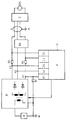
Das hier gewählte Ausführungsbeispiel bezieht sich auf ein Vorschaltgerät zum Betreiben einer Wechselstrom-Hochdruck-Gasentladungslampe in Kraftfahrzeugen. Das Vorschaltgerät wird dabei aus der Fahrzeugbatterie (B) gespeist. Bei dem hier vorliegenden Ausführungsbeispiel ist ein DC/DC-Wandler (D) elektrisch Leitend mit der Fahrzeugbatterie (B) und der Fahrzeugmasse (M) des Kraftfahrzeugs verbunden. Der DC/DC-Wandler (D) erzeugt aus der Batteriespannung der Fahrzeugbatterie (B) eine Lampenversorgungsspannung, die an der zweiten Ausgangsklemme (K2) anliegt und erzeugt hier beispielhaft aus der Spannung der Fahrzeugbatterie (B) eine Zündhilfsspannung, die an der dritten Ausgangsklemme (K3) anliegt. Die erste Ausgangsklemme (K1) des DC/DC-Wandlers (D) liefert das Bezugspotential für die Zündhilfsspannung und die Lampenversorgungsspannung.The exemplary embodiment selected here relates to a ballast for operating an AC high-pressure gas discharge lamp in motor vehicles. The ballast is from the Vehicle battery (B) powered. In the present embodiment, a DC / DC converter (D) is electrically conductively connected to the vehicle battery (B) and the vehicle mass (M) of the motor vehicle. The DC / DC converter (D) generates a lamp supply voltage from the battery voltage of the vehicle battery (B), which is present at the second output terminal (K2), and generates an auxiliary ignition voltage from the voltage of the vehicle battery (B), for example, at the third output terminal (K3) is present. The first output terminal (K1) of the DC / DC converter (D) supplies the reference potential for the auxiliary ignition voltage and the lamp supply voltage.
Der DC/DC-Wandler (D) ist hier über die dritte Ausgangsklemme (K3), an der die Zündhilfsspannung anliegt, elektrisch leitend mit einer Zündeinrichtung (Z) verbunden, die aus der anliegenden Zündhilfsspannung eine Zündspannung bildet, die geeignet ist, die Hochdruck-Gasentladungslampe (GDL), die an die Zündeinrichtung (Z) angeschlossen ist, zu zünden.The DC / DC converter (D) is here via the third output terminal (K3), to which the auxiliary ignition voltage is applied, electrically conductively connected to an ignition device (Z), which forms an ignition voltage from the applied auxiliary ignition voltage that is suitable for high pressure -Gas discharge lamp (GDL), which is connected to the ignition device (Z), to ignite.
Bei dem hier gewählten Ausführungsbeispiel wird die Lampenversorgungsspannung, die an der zweiten Ausgangsklemme (K2) anliegt, einem Wechselrichter (BS), der hier als ein Brückenschalter (BS) ausgebildet ist, zugeführt, der zudem über die erste Ausgangsklemme (K1) mit dem DC/DC-Wandler (D) verbunden ist. Dieser Brückenschalter (BS) ist z. B. dann erforderlich, wenn die zu betreibende Hochdruck-Gasentladungslampe (GDL) eine Wechselstrom-Hochdruck-Gasentladungslampe (GDL) ist. Der Brückenschalter (BS) ist hier über die Zündeinrichtung (Z) mit der Hochdruck-Gasentladungslampe (GDL) verbunden. Werden von einem Vorschaltgerät mehrere Hochdruck-Gasentladungslampen (GDL) z. B. alternativ betrieben oder ist die mindestens eine Zündeinrichtung (Z) räumlich getrennt von dem übrigen Vorschaltgerät angeordnet, so kann die Zündeinrichtung (Z) über ein abgeschirmtes Kabel (K) mit dem DC/DC-Wandler (D) und/oder dem Brückenschalter (BS) verbunden sein. Das abgeschirmte Kabel (K) ist dabei mit der Fahrzeugmasse (M) verbunden.In the exemplary embodiment selected here, the lamp supply voltage, which is present at the second output terminal (K2), is fed to an inverter (BS), which is designed here as a bridge switch (BS), which also connects to the DC via the first output terminal (K1) / DC converter (D) is connected. This bridge switch (BS) is e.g. B. required if the high-pressure gas discharge lamp (GDL) to be operated is an AC high-pressure gas discharge lamp (GDL). The bridge switch (BS) is here connected to the high-pressure gas discharge lamp (GDL) via the ignition device (Z). Are several high pressure gas discharge lamps (GDL) z. B. operated alternatively or the at least one ignition device (Z) is spatially separated from the rest of the ballast, the ignition device (Z) can be via a shielded cable (K) with the DC / DC converter (D) and / or the bridge switch (BS). The shielded cable (K) is connected to the vehicle ground (M).
Die erste Ausgangsklemme (K1) des DC/DC-Wandlers (D) ist elektrisch leitend über einen niederohmigen ersten Meßwiderstand (R1) mit der Fahrzeugmasse (M) verbunden. Die erste Ausgangsklemme (K1) ist zudem mit einer Fehlerstromermittlungseinrichtung (FI) einer Sicherheitseinrichtung (S) verbunden. Werden spannungsführende Teile des Vorschaltgerätes berührt, so fließt ein Fehlerstrom über die Fahrzeugmasse (M) und den ersten Meßwiderstand (R1). An dem niederohmigen ersten Meßwiderstand (R1) fällt eine Spannung ab und die Fehlerstromermittlungseinrichtung (FI) bestimmt zu diesem Spannungsabfall den entsprechenden Fehlerstrom. Eine Auswerte- und Schalteinrichtung (A) der Sicherheitseinrichtung (S) wertet den gemessenen Fehlerstrom aus und erzeugt ein Abschaltsignal, wenn der Fehlerstrom einen vorgegebenen Wert übersteigt. Der vorgegebene Wert kann dabei bei beispielhaft etwa 20 bis 30 mA liegen, was zu einem sehr großen Berührungsschutz und einer sehr großen Sicherheit für Personen führt, die spannungsführende Teile des Vorschaltgerätes berühren. Die Sicherheitseinrichtung (S) ist elektrisch leitend mit dem DC/DC-Wandler (D) verbunden und führt diesem das Abschaltsignal derart zu, daß der DC/DC-Wandler (D) abgeschaltet wird und somit das gesamte Vorschaltgerät dauerhaft abgeschaltet wird bis es erneut eingeschaltet wird. Eine Messung derart niedriger Fehlerströme ist nur möglich und auch nur mit einer derart hohen Sicherheit durchzuführen, wenn die an den Ausgangsklemmen (K1, K2, K3) erzeugten Ausgangsspannungen galvanisch getrennt von der Spannungsversorgung durch die Fahrzeugbatterie (B) erzeugt worden sind. Hierzu kann z. B. ein entsprechend aufgebauter Transformator dienen, der in der Zeichnung innerhalb des Bauteils, das den DC/DC-Wandler (D) darstellt, angedeutet ist. Entsprechend der Zeichnung weist der DC/DC-Wandler (D) zudem noch Gleichrichter auf.The first output terminal (K1) of the DC / DC converter (D) is electrically conductively connected to the vehicle ground (M) via a low-resistance first measuring resistor (R1). The first output terminal (K1) is also connected to a residual current detection device (FI) of a safety device (S). If live parts of the ballast are touched, a fault current flows over the vehicle mass (M) and the first measuring resistor (R1). A voltage drops across the low-resistance first measuring resistor (R1) and the fault current detection device (FI) determines the corresponding fault current for this voltage drop. An evaluation and switching device (A) of the safety device (S) evaluates the measured fault current and generates a switch-off signal if the fault current exceeds a predetermined value. The specified value can be, for example, about 20 to 30 mA, which leads to a very large protection against accidental contact and a very high level of safety for people who touch live parts of the ballast. The safety device (S) is electrically conductively connected to the DC / DC converter (D) and feeds the switch-off signal to it in such a way that the DC / DC converter (D) is switched off and the entire ballast is therefore switched off permanently until it is again is switched on. A measurement of such low fault currents is only possible and can only be carried out with such a high level of safety if the output voltages generated at the output terminals (K1, K2, K3) have been generated in an electrically isolated manner from the voltage supply by the vehicle battery (B). For this, e.g. B. serve a correspondingly constructed transformer, which is indicated in the drawing within the component that represents the DC / DC converter (D) is. According to the drawing, the DC / DC converter (D) also has a rectifier.
Der niederohmige erste Meßwiderstand (R1) kann beispielhaft einen Widerstandswert von etwa 1 Ohm aufweisen. Der Widerstandswert ist dabei jedoch je nach Anwendung unterschiedlich zu wählen.The low-resistance first measuring resistor (R1) can have, for example, a resistance value of approximately 1 ohm. The resistance value should be chosen differently depending on the application.
Um z. B. Kurzschlüsse zwischen den Leitungen zur Lampenversorgung erfassen zu können, die zu Fehlfunktionen des Vorschaltgerätes und zur Zerstörung von Teilen des Vorschaltgerätes führen können, ist hier in der Verbindung zwischen der ersten Ausgangsklemme (K1) und dem Brückenschalter (BS) ein zweiter Meßwiderstand (R2) angeordnet. Die Verbindung zwischen dem zweiten Meßwiderstand (R2) und dem Brückenschalter (BS) ist elektrisch leitend mit einer Lampenstromermittlungseinrichtung (LI) der Sicherheitseinrichtung (SI) verbunden, die wiederum mit der Auswerte- und Schalteinrichtung (A) der Sicherheitseinrichtung (S) verbunden ist, um bei einem z. B. vorliegenden Kurzschluß oder bei Fehlern im Lampenstrom ein Abschaltsignal für den DC/DC-Wandler (D) zu erzeugen.To z. B. To be able to detect short circuits between the lines for lamp supply, which can lead to malfunction of the ballast and destruction of parts of the ballast, here is a second measuring resistor (R2) in the connection between the first output terminal (K1) and the bridge switch (BS) ) arranged. The connection between the second measuring resistor (R2) and the bridge switch (BS) is electrically conductively connected to a lamp current determining device (LI) of the safety device (SI), which in turn is connected to the evaluation and switching device (A) of the safety device (S), to at a z. B. present short circuit or errors in the lamp current to generate a shutdown signal for the DC / DC converter (D).
Um z. B. Fehler in dem Zündstrom oder Kurzschlüsse zwischen den Leitungen zur Lampenversorgung feststellen zu können, ist zwischen der dritten Ausgangsklemme (K3) und der Zündeinrichtung (Z) ein dritter Meßwiderstand (R3) angeordnet. Die Verbindung zwischen dem dritten Meßwiderstand (R3) und der Zündeinrichtung (Z) ist elektrisch leitend mit einer Zündstromermittlungseinrichtung (ZI) der Sicherheitseinrichtung (S) verbunden und ist mit der Auswerte- und Schalteinrichtung (A) der Sicherheitseinrichtung (S) zur Erzeugung eines Abschaltsignals für den DC/DC-Wandler (D) verbunden, wenn z. B. ein Kurzschluß oder ein Fehler in dem Zündstrom vorliegt.To z. B. To determine errors in the ignition current or short circuits between the lines for lamp supply, a third measuring resistor (R3) is arranged between the third output terminal (K3) and the ignition device (Z). The connection between the third measuring resistor (R3) and the ignition device (Z) is electrically conductively connected to an ignition current detection device (ZI) of the safety device (S) and is connected to the evaluation and switching device (A) of the safety device (S) for generating a switch-off signal connected for the DC / DC converter (D) if e.g. B. there is a short circuit or an error in the ignition current.
Die zweite Ausgangsklemme (K2) des DC/DC-Wandlers (D) ist elektrisch leitend zur Ermittlung der Lampenversorgungsspannung mit einer Lampenspannungsermittlungseinrichtung (LU) der Sicherheitseinrichtung (S) verbunden und ebenfalls an die Auswerte- und Schalteinrichtung (A) angeschlossen. Zur Ermittlung der Zündhilfsspannung ist eine Zündhilfsspannungsermittlungseinrichtung (ZU) der Sicherheitseinrichtung (S) elektrisch leitend sowohl mit der dritten Ausgangsklemme (K3) als auch mit der Auswerte- und Schalteinrichtung (A) verbunden.The second output terminal (K2) of the DC / DC converter (D) is electrically conductively connected to a lamp voltage determining device (LU) of the safety device (S) in order to determine the lamp supply voltage and is also connected to the evaluation and switching device (A). To determine the auxiliary ignition voltage, an auxiliary ignition voltage determination device (ZU) of the safety device (S) is electrically conductively connected both to the third output terminal (K3) and to the evaluation and switching device (A).
Werden durch die Fehlerstromermittlungseinrichtung (FI) und/oder die Lampenspannungsermittlungseinrichtung (LU) und/oder die Zündhilfsspannungsermittlungseinrichtung (ZU) und/oder die Lampenstromermittlungseinrichtung (LI) und/oder die Zündstromermittlungseinrichtung (ZI) Meßwerte ermittelt, die von vorgegebenen in der Auswerte- und Schaltwerteeinrichtung (A) z. B. gespeicherten Werte abweichen, so erzeugt die Auswerte- und Schalteinrichtung (A) der Sicherheitseinrichtung (S) Abschaltsignale, die hier den DC/DC-Wandler (D) derart ansteuern, daß dieser abgeschaltet wird und das gesamte Vorschaltgerät dauerhaft bis zum nächsten Einschalten außer Betrieb setzt.Are measured values determined by the fault current detection device (FI) and / or the lamp voltage detection device (LU) and / or the auxiliary ignition voltage detection device (ZU) and / or the lamp current detection device (LI) and / or the ignition current detection device (ZI) in the evaluation and Switching value device (A) z. B. stored values deviate, the evaluation and switching device (A) of the safety device (S) generates shutdown signals which drive the DC / DC converter (D) in such a way that it is switched off and the entire ballast permanently until the next switch-on decommissioning.
Bei anderen Ausführungsbeispielen können die ermittelten Meßwerte insbesondere dazu dienen, die Lampenleistung des Vorschaltgerätes in Abhängigkeit von unterschiedlichen Parametern wie z- B. Einschaltzeiten, Kaltstart, Heißstart und Lampentemperatur zu steuern und/oder zu regeln.In other exemplary embodiments, the measured values determined can be used, in particular, to control and / or regulate the lamp power of the ballast as a function of different parameters such as, for example, switch-on times, cold start, hot start and lamp temperature.
Bei anderen Ausführungsbeispielen kann z. B. auf die Verwendung des Brückenschalters (BS) verzichtet werden, wenn die anzusteuernde Hochdruck-Gasentladungslampe (GDL) eine Gleichstrom-Hochdruck-Gasentladungslampe (GDL) ist.In other embodiments, e.g. B. the use of the bridge switch (BS) can be dispensed with, when the high pressure gas discharge lamp (GDL) to be controlled is a direct current high pressure gas discharge lamp (GDL).
Bei einem anderen Ausführungsbeispiel zur Ansteuerung einer Wechselstrom-Hochdruck-Gasentladungslampe (GDL) kann der DC/DC-Wandler (D) auch durch einen Wechselrichter (BS) oder einen DC/AC-Wandler (BS) ersetzt werden. Auch in diesem Fall kann auf einen zusätzlichen Brückenschalter (BS) verzichtet werden.In another exemplary embodiment for controlling an AC high-pressure gas discharge lamp (GDL), the DC / DC converter (D) can also be replaced by an inverter (BS) or a DC / AC converter (BS). In this case too, an additional bridge switch (BS) can be dispensed with.
Die Zündeinrichtung (Z) kann in bekannter Weise sowohl als ein Überlagerungszündgerät oder ein Resonanzzündgerät ausgebildet sein.The ignition device (Z) can be designed in a known manner both as a superimposed ignition device or a resonance ignition device.
- (A)(A)
- Auswerte- und SchalteinrichtungEvaluation and switching device
- (B)(B)
- FahrzeugbatterieVehicle battery
- (BS)(BS)
- WechselrichterInverter
- (D)(D)
- DC/DC-WandlerDC / DC converter
- (FI)(FI)
- FehlerstromermittlungseinrichtungResidual current determination device
- (GDL)(GDL)
- Hochdruck-GasentladungslampeHigh pressure gas discharge lamp
- (K)(K)
- Kabelelectric wire
- (K1)(K1)
- erste Ausgangsklemmefirst output terminal
- (K2)(K2)
- zweite Ausgangsklemmesecond output terminal
- (K3)(K3)
- dritte Ausgangsklemmethird output terminal
- (LU)(LU)
- LampenspannungsermittlungseinrichtungLamp voltage detection device
- (LI)(LI)
- LampenstromermittlungseinrichtungLamp current detection device
- (M)(M)
- FahrzeugmasseVehicle mass
- (R1)(R1)
- erster Meßwiderstandfirst measuring resistor
- (R2)(R2)
- zweiter Meßwiderstandsecond measuring resistor
- (R3)(R3)
- dritter Meßwiderstandthird measuring resistor
- (S)(S)
- SicherheitseinrichtungSafety device
- (Z)(Z)
- ZündeinrichtungIgnition device
- (ZI)(ZI)
- ZündstromermittlungseinrichtungIgnition current detection device
- (ZU)(TO)
- ZündhilfsspannungsermittlungseinrichtungAuxiliary ignition voltage determination device
Claims (14)
Applications Claiming Priority (2)
| Application Number | Priority Date | Filing Date | Title |
|---|---|---|---|
| DE4117589 | 1991-05-29 | ||
| DE4117589A DE4117589A1 (en) | 1991-05-29 | 1991-05-29 | CONTROL UNIT FOR HIGH PRESSURE GAS DISCHARGE LAMPS IN MOTOR VEHICLES |
Publications (3)
| Publication Number | Publication Date |
|---|---|
| EP0515977A2 true EP0515977A2 (en) | 1992-12-02 |
| EP0515977A3 EP0515977A3 (en) | 1993-02-24 |
| EP0515977B1 EP0515977B1 (en) | 1996-01-03 |
Family
ID=6432715
Family Applications (1)
| Application Number | Title | Priority Date | Filing Date |
|---|---|---|---|
| EP92108556A Expired - Lifetime EP0515977B1 (en) | 1991-05-29 | 1992-05-21 | Electronic ballast for high pressure discharge lamps used in automotive applications |
Country Status (5)
| Country | Link |
|---|---|
| US (1) | US5241242A (en) |
| EP (1) | EP0515977B1 (en) |
| AU (1) | AU653219B2 (en) |
| DE (2) | DE4117589A1 (en) |
| ES (1) | ES2084213T3 (en) |
Cited By (3)
| Publication number | Priority date | Publication date | Assignee | Title |
|---|---|---|---|---|
| EP0567108A1 (en) * | 1992-04-23 | 1993-10-27 | MAGNETI MARELLI S.p.A. | A control circuit for a gas discharge lamp, particularly for use in motor vehicles |
| EP0615403A2 (en) * | 1993-03-09 | 1994-09-14 | Everbrite Inc. | Load fault detector for high frequency luminous tube power supplies |
| EP1309232B1 (en) * | 1997-05-16 | 2014-03-05 | Denso Corporation | High voltage discharge lamp device |
Families Citing this family (21)
| Publication number | Priority date | Publication date | Assignee | Title |
|---|---|---|---|---|
| JP3206966B2 (en) * | 1992-07-03 | 2001-09-10 | 株式会社小糸製作所 | Lighting circuit for vehicle discharge lamps |
| BE1006978A3 (en) * | 1993-04-02 | 1995-02-07 | Koninkl Philips Electronics Nv | Shifting. |
| DE4342590A1 (en) * | 1993-12-14 | 1995-06-22 | Bosch Gmbh Robert | Clocked power supply |
| JP3197169B2 (en) * | 1994-09-08 | 2001-08-13 | 株式会社小糸製作所 | Lighting circuit of discharge lamp |
| JP3521501B2 (en) * | 1994-10-12 | 2004-04-19 | 株式会社デンソー | High pressure discharge lamp lighting device |
| US5646484A (en) * | 1994-11-02 | 1997-07-08 | Litebeams, Inc. | High reliability incandescent portable illumination system |
| US5523653A (en) * | 1995-02-10 | 1996-06-04 | Tivoli Industries, Inc. | Lighting apparatus with improved current overload protection circuit |
| JP3210561B2 (en) * | 1995-06-14 | 2001-09-17 | 株式会社小糸製作所 | Discharge lamp lighting circuit |
| US5675220A (en) * | 1995-07-17 | 1997-10-07 | Adac Plastics, Inc. | Power supply for vehicular neon light |
| JP3412421B2 (en) * | 1996-10-14 | 2003-06-03 | 株式会社デンソー | Discharge lamp lighting device |
| JP3207134B2 (en) * | 1997-05-16 | 2001-09-10 | 株式会社小糸製作所 | Lighting circuit of discharge lamp |
| EP0955793B1 (en) * | 1998-05-08 | 2004-03-03 | Denso Corporation | Discharge lamp apparatus |
| DE19848756A1 (en) * | 1998-10-22 | 2000-04-27 | Hella Kg Hueck & Co | Method and device for short-circuit detection in a ballast of a high-pressure gas discharge lamp in a motor vehicle |
| CN1171510C (en) * | 1999-03-19 | 2004-10-13 | 松下电工株式会社 | Ballast for discharge lamp |
| EP1227706B1 (en) * | 2001-01-24 | 2012-11-28 | City University of Hong Kong | Novel circuit designs and control techniques for high frequency electronic ballasts for high intensity discharge lamps |
| US6624585B2 (en) * | 2001-09-10 | 2003-09-23 | Infocus Corporation | Ultra-compact igniter circuit for arc discharge lamp |
| TW586334B (en) * | 2001-09-10 | 2004-05-01 | Matsushita Electric Ind Co Ltd | Self-ballasted fluorescent lamp |
| US7430380B2 (en) * | 2005-09-23 | 2008-09-30 | Xerox Corporation | Printing system |
| US7670010B2 (en) * | 2006-09-21 | 2010-03-02 | Dell Products L.P. | System and method for projector lamp safety interlock |
| US8460284B2 (en) * | 2007-10-26 | 2013-06-11 | Encision, Inc. | Multiple parameter fault detection in electrosurgical instrument shields |
| JP5576638B2 (en) * | 2009-11-06 | 2014-08-20 | パナソニック株式会社 | Lighting device and headlight lighting device, headlight, vehicle using the same |
Citations (4)
| Publication number | Priority date | Publication date | Assignee | Title |
|---|---|---|---|---|
| US4563719A (en) * | 1982-08-30 | 1986-01-07 | Nilssen Ole K | Ballasts with built-in ground-fault protection |
| US4943886A (en) * | 1989-02-10 | 1990-07-24 | Etta Industries, Inc. | Circuitry for limiting current between power inverter output terminals and ground |
| DE4002334A1 (en) * | 1989-01-26 | 1990-08-02 | Koito Mfg Co Ltd | Electric lamp lighting circuit with protection against overload - includes protective switch opened automatically on de-energisation of relay coil in series with manual lighting switch |
| WO1991002442A1 (en) * | 1989-08-05 | 1991-02-21 | Robert Bosch Gmbh | Process for igniting a gas-discharge lamp |
Family Cites Families (18)
| Publication number | Priority date | Publication date | Assignee | Title |
|---|---|---|---|---|
| DE1987218U (en) * | 1968-06-12 | Fritz Hellige & Co. GmbH, Fabrik wissenschaftlicher Apparate, 7800 Freiburg/DE | Electrical device protected against the passage of a fault current | |
| DE1195863B (en) * | 1962-04-09 | 1965-07-01 | Continental Elektro Ind Ag | Earth resistance meter using the compensation method |
| DE1918417A1 (en) * | 1969-04-11 | 1970-10-15 | Bbc Brown Boveri & Cie | Device for earth connection protection for DC circuits |
| AT331350B (en) * | 1973-04-25 | 1976-08-10 | Norma Messtechnik Gmbh | EARTH RESISTANCE METER |
| SU517190A1 (en) * | 1974-02-08 | 1978-05-05 | Ордена Трудового Красного Знамени институт физики АН Белорусской ССР | Device for power supply of laser pumping lamps |
| SU877803A1 (en) * | 1980-02-26 | 1981-10-30 | Предприятие П/Я А-3526 | Device for pulse ignition of xenon tubes |
| GB2110890B (en) * | 1981-12-07 | 1985-06-26 | Krauss Innovatron | Frequency controlled excitation of a gas discharge lamp |
| DE3346387A1 (en) * | 1983-12-22 | 1985-07-04 | Standard Elektrik Lorenz Ag, 7000 Stuttgart | Circuit arrangement for monitoring short circuits to earth and frame |
| US4613934A (en) * | 1984-03-19 | 1986-09-23 | Pacholok David R | Power supply for gas discharge devices |
| DE3445817A1 (en) * | 1984-12-15 | 1986-06-26 | Wolfgang Dipl.-Ing. 6232 Bad Soden Renner | Circuit arrangement for operating a high-pressure discharge lamp from a low-voltage DC voltage |
| NL8600813A (en) * | 1986-03-28 | 1987-10-16 | Philips Nv | SWITCHING DEVICE FOR OPERATING A HIGH-PRESSURE DISCHARGE LAMP. |
| US4952848A (en) * | 1988-07-05 | 1990-08-28 | North American Philips Corporation | Signal generating circuit for ballast control of discharge lamps |
| JPH038299A (en) * | 1989-06-02 | 1991-01-16 | Koito Mfg Co Ltd | Lighting circuit for high-pressure discharge lamp for vehicle |
| DE3928810A1 (en) * | 1989-08-31 | 1991-03-07 | Philips Patentverwaltung | CIRCUIT ARRANGEMENT FOR FEEDING A LOAD |
| DE3929029A1 (en) * | 1989-09-01 | 1991-03-07 | Bosch Gmbh Robert | CIRCUIT ARRANGEMENT FOR OPERATING A GAS DISCHARGE LAMP |
| US5047695A (en) * | 1990-02-20 | 1991-09-10 | General Electric Company | Direct current (DC) acoustic operation of xenon-metal halide lamps using high-frequency ripple |
| DE4015398A1 (en) * | 1990-05-14 | 1991-11-21 | Hella Kg Hueck & Co | Starter control circuit for HV gas discharge lamp in road vehicle |
| US5084653A (en) * | 1990-07-18 | 1992-01-28 | Nilssen Ole K | Power-line-isolated dimmable electronic ballast |
-
1991
- 1991-05-29 DE DE4117589A patent/DE4117589A1/en not_active Withdrawn
-
1992
- 1992-05-04 AU AU16001/92A patent/AU653219B2/en not_active Ceased
- 1992-05-21 EP EP92108556A patent/EP0515977B1/en not_active Expired - Lifetime
- 1992-05-21 ES ES92108556T patent/ES2084213T3/en not_active Expired - Lifetime
- 1992-05-21 DE DE59204878T patent/DE59204878D1/en not_active Expired - Lifetime
- 1992-05-28 US US07/889,425 patent/US5241242A/en not_active Expired - Lifetime
Patent Citations (4)
| Publication number | Priority date | Publication date | Assignee | Title |
|---|---|---|---|---|
| US4563719A (en) * | 1982-08-30 | 1986-01-07 | Nilssen Ole K | Ballasts with built-in ground-fault protection |
| DE4002334A1 (en) * | 1989-01-26 | 1990-08-02 | Koito Mfg Co Ltd | Electric lamp lighting circuit with protection against overload - includes protective switch opened automatically on de-energisation of relay coil in series with manual lighting switch |
| US4943886A (en) * | 1989-02-10 | 1990-07-24 | Etta Industries, Inc. | Circuitry for limiting current between power inverter output terminals and ground |
| WO1991002442A1 (en) * | 1989-08-05 | 1991-02-21 | Robert Bosch Gmbh | Process for igniting a gas-discharge lamp |
Cited By (4)
| Publication number | Priority date | Publication date | Assignee | Title |
|---|---|---|---|---|
| EP0567108A1 (en) * | 1992-04-23 | 1993-10-27 | MAGNETI MARELLI S.p.A. | A control circuit for a gas discharge lamp, particularly for use in motor vehicles |
| EP0615403A2 (en) * | 1993-03-09 | 1994-09-14 | Everbrite Inc. | Load fault detector for high frequency luminous tube power supplies |
| EP0615403A3 (en) * | 1993-03-09 | 1994-11-02 | Everbrite Inc | Load fault detector for high frequency luminous tube power supplies. |
| EP1309232B1 (en) * | 1997-05-16 | 2014-03-05 | Denso Corporation | High voltage discharge lamp device |
Also Published As
| Publication number | Publication date |
|---|---|
| US5241242A (en) | 1993-08-31 |
| AU653219B2 (en) | 1994-09-22 |
| EP0515977B1 (en) | 1996-01-03 |
| AU1600192A (en) | 1992-12-03 |
| EP0515977A3 (en) | 1993-02-24 |
| DE4117589A1 (en) | 1992-12-03 |
| DE59204878D1 (en) | 1996-02-15 |
| ES2084213T3 (en) | 1996-05-01 |
Similar Documents
| Publication | Publication Date | Title |
|---|---|---|
| EP0515977B1 (en) | Electronic ballast for high pressure discharge lamps used in automotive applications | |
| DE4002334A1 (en) | Electric lamp lighting circuit with protection against overload - includes protective switch opened automatically on de-energisation of relay coil in series with manual lighting switch | |
| DE3108548C2 (en) | Ignition circuit for a high pressure metal vapor discharge lamp | |
| DE19705776A1 (en) | Discharge lamp turning ON circuit e.g. for metal halide lamp of light source in vehicle | |
| DE10133007A1 (en) | Entladungslampenzündschaltkreis | |
| DE10012860B4 (en) | Control system for an alternator | |
| DE4136486A1 (en) | High power gas discharge lamp ballast for ignition and operation of lamp - uses bridge stage switched between DC mode for lamp ignition and AC mode for subsequent operation of lamp | |
| DE4439885A1 (en) | Device for operating a gas discharge lamp | |
| EP0614052A2 (en) | Automatic ignition device | |
| EP1707880B1 (en) | Apparatus for detecting the presence of a flame in a combustion chamber and ignition device for a burner | |
| DE2718798A1 (en) | PROTECTIVE CIRCUIT FOR DC MAIN CIRCUIT | |
| DE3204449C2 (en) | ||
| WO2009077221A1 (en) | Method and device for operating an electric drive with the aid of a phase angle control | |
| EP1843645B1 (en) | Switching assembly for high pressure gas discharge lamps | |
| DE102013203732A1 (en) | Circuit arrangement and method for operating at least one light source | |
| EP0534280B1 (en) | Ballast for starting and operating high-pressure electric discharge lamps | |
| EP0540924B1 (en) | Ballast for starting and operating high pressure discharge lamps | |
| EP0632277B1 (en) | Testing device | |
| DE19912376C2 (en) | Ionenstrommeßgerät | |
| DE4127214A1 (en) | LOW VOLTAGE MELTFUSE | |
| DE102017216227B3 (en) | Control circuit for controlling an ignition coil of an internal combustion engine and method for operating such a control circuit | |
| DE102016220889B4 (en) | Power converter device, electrical drive system and method for operating a power converter arrangement | |
| WO2008098532A1 (en) | State display device for an electric fuse cut-out | |
| DE4323731A1 (en) | Tester | |
| DE19958039C2 (en) | Device and method for avoiding current and voltage peaks |
Legal Events
| Date | Code | Title | Description |
|---|---|---|---|
| PUAI | Public reference made under article 153(3) epc to a published international application that has entered the european phase |
Free format text: ORIGINAL CODE: 0009012 |
|
| AK | Designated contracting states |
Kind code of ref document: A2 Designated state(s): DE ES FR GB IT NL SE |
|
| PUAL | Search report despatched |
Free format text: ORIGINAL CODE: 0009013 |
|
| AK | Designated contracting states |
Kind code of ref document: A3 Designated state(s): DE ES FR GB IT NL SE |
|
| 17P | Request for examination filed |
Effective date: 19930311 |
|
| 17Q | First examination report despatched |
Effective date: 19950206 |
|
| ITF | It: translation for a ep patent filed |
Owner name: INTERPATENT ST.TECN. BREV. |
|
| GRAA | (expected) grant |
Free format text: ORIGINAL CODE: 0009210 |
|
| AK | Designated contracting states |
Kind code of ref document: B1 Designated state(s): DE ES FR GB IT NL SE |
|
| GBT | Gb: translation of ep patent filed (gb section 77(6)(a)/1977) |
Effective date: 19960106 |
|
| REF | Corresponds to: |
Ref document number: 59204878 Country of ref document: DE Date of ref document: 19960215 |
|
| ET | Fr: translation filed | ||
| REG | Reference to a national code |
Ref country code: ES Ref legal event code: FG2A Ref document number: 2084213 Country of ref document: ES Kind code of ref document: T3 |
|
| PLBE | No opposition filed within time limit |
Free format text: ORIGINAL CODE: 0009261 |
|
| STAA | Information on the status of an ep patent application or granted ep patent |
Free format text: STATUS: NO OPPOSITION FILED WITHIN TIME LIMIT |
|
| 26N | No opposition filed | ||
| PGFP | Annual fee paid to national office [announced via postgrant information from national office to epo] |
Ref country code: SE Payment date: 19980525 Year of fee payment: 7 |
|
| PG25 | Lapsed in a contracting state [announced via postgrant information from national office to epo] |
Ref country code: SE Free format text: LAPSE BECAUSE OF NON-PAYMENT OF DUE FEES Effective date: 19990522 |
|
| EUG | Se: european patent has lapsed |
Ref document number: 92108556.9 |
|
| PGFP | Annual fee paid to national office [announced via postgrant information from national office to epo] |
Ref country code: NL Payment date: 20000424 Year of fee payment: 9 |
|
| PGFP | Annual fee paid to national office [announced via postgrant information from national office to epo] |
Ref country code: GB Payment date: 20000427 Year of fee payment: 9 |
|
| PG25 | Lapsed in a contracting state [announced via postgrant information from national office to epo] |
Ref country code: GB Free format text: LAPSE BECAUSE OF NON-PAYMENT OF DUE FEES Effective date: 20010521 |
|
| PG25 | Lapsed in a contracting state [announced via postgrant information from national office to epo] |
Ref country code: NL Free format text: LAPSE BECAUSE OF NON-PAYMENT OF DUE FEES Effective date: 20011201 |
|
| GBPC | Gb: european patent ceased through non-payment of renewal fee |
Effective date: 20010521 |
|
| NLV4 | Nl: lapsed or anulled due to non-payment of the annual fee |
Effective date: 20011201 |
|
| PGFP | Annual fee paid to national office [announced via postgrant information from national office to epo] |
Ref country code: FR Payment date: 20060515 Year of fee payment: 15 |
|
| PGFP | Annual fee paid to national office [announced via postgrant information from national office to epo] |
Ref country code: IT Payment date: 20060531 Year of fee payment: 15 |
|
| PGFP | Annual fee paid to national office [announced via postgrant information from national office to epo] |
Ref country code: ES Payment date: 20060621 Year of fee payment: 15 |
|
| REG | Reference to a national code |
Ref country code: FR Ref legal event code: ST Effective date: 20080131 |
|
| PG25 | Lapsed in a contracting state [announced via postgrant information from national office to epo] |
Ref country code: FR Free format text: LAPSE BECAUSE OF NON-PAYMENT OF DUE FEES Effective date: 20070531 |
|
| REG | Reference to a national code |
Ref country code: ES Ref legal event code: FD2A Effective date: 20070522 |
|
| PG25 | Lapsed in a contracting state [announced via postgrant information from national office to epo] |
Ref country code: ES Free format text: LAPSE BECAUSE OF NON-PAYMENT OF DUE FEES Effective date: 20070522 |
|
| PG25 | Lapsed in a contracting state [announced via postgrant information from national office to epo] |
Ref country code: IT Free format text: LAPSE BECAUSE OF NON-PAYMENT OF DUE FEES Effective date: 20070521 |
|
| PGFP | Annual fee paid to national office [announced via postgrant information from national office to epo] |
Ref country code: DE Payment date: 20110518 Year of fee payment: 20 |
|
| REG | Reference to a national code |
Ref country code: DE Ref legal event code: R071 Ref document number: 59204878 Country of ref document: DE |
|
| REG | Reference to a national code |
Ref country code: DE Ref legal event code: R071 Ref document number: 59204878 Country of ref document: DE |
|
| PG25 | Lapsed in a contracting state [announced via postgrant information from national office to epo] |
Ref country code: DE Free format text: LAPSE BECAUSE OF EXPIRATION OF PROTECTION Effective date: 20120522 |