EP0806312A2 - Foldable top for convertible vehicle - Google Patents
Foldable top for convertible vehicle Download PDFInfo
- Publication number
- EP0806312A2 EP0806312A2 EP97103396A EP97103396A EP0806312A2 EP 0806312 A2 EP0806312 A2 EP 0806312A2 EP 97103396 A EP97103396 A EP 97103396A EP 97103396 A EP97103396 A EP 97103396A EP 0806312 A2 EP0806312 A2 EP 0806312A2
- Authority
- EP
- European Patent Office
- Prior art keywords
- parts
- tensioning bracket
- fabric tensioning
- folding
- roof
- Prior art date
- Legal status (The legal status is an assumption and is not a legal conclusion. Google has not performed a legal analysis and makes no representation as to the accuracy of the status listed.)
- Granted
Links
Images


Classifications
-
- B—PERFORMING OPERATIONS; TRANSPORTING
- B60—VEHICLES IN GENERAL
- B60J—WINDOWS, WINDSCREENS, NON-FIXED ROOFS, DOORS, OR SIMILAR DEVICES FOR VEHICLES; REMOVABLE EXTERNAL PROTECTIVE COVERINGS SPECIALLY ADAPTED FOR VEHICLES
- B60J7/00—Non-fixed roofs; Roofs with movable panels, e.g. rotary sunroofs
- B60J7/08—Non-fixed roofs; Roofs with movable panels, e.g. rotary sunroofs of non-sliding type, i.e. movable or removable roofs or panels, e.g. let-down tops or roofs capable of being easily detached or of assuming a collapsed or inoperative position
- B60J7/12—Non-fixed roofs; Roofs with movable panels, e.g. rotary sunroofs of non-sliding type, i.e. movable or removable roofs or panels, e.g. let-down tops or roofs capable of being easily detached or of assuming a collapsed or inoperative position foldable; Tensioning mechanisms therefor, e.g. struts
- B60J7/1226—Soft tops for convertible vehicles
- B60J7/1234—Soft tops for convertible vehicles characterised by arches, e.g. shape or material
- B60J7/1247—Tensioning bow at rear of soft top
Definitions
- the invention relates to a folding top for a convertible vehicle according to the preamble of claim 1.
- the folding top has a top fabric tensioning bracket connected to its roof skin, which in its longitudinal direction essentially follows the roof skin contour in the rear area. If the folding top is designed as a component that can be lowered into a top trough, a minimum size corresponding to the top fabric tensioning bracket is provided for a receiving opening of the top trough and thus overall a correspondingly space-consuming movement space in the vehicle body is required.
- the convertible top tensioning bracket is designed as a multi-part assembly, so that positive control of the individual parts of the convertible top tensioning bracket is possible via respective connecting links to the convertible top drive acting on the convertible top tensioning bracket.
- the force-controlled movement of the individual parts of the top fabric tensioning bracket also enables a partial tensioning or relaxation of the roof skin with little effort, so that unintentional elongations or overexpansions of the top fabric are avoided and the roof skin area provided in the area of the rear window can be adapted to an increase in the window area.
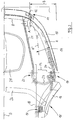
- a folding top assembly (generally designated 1) (without roof skin) for a convertible vehicle is illustrated, with a top frame parts 2 and 3 on the edge having top frame in the rear end area cooperating with a top fabric tensioning bracket 4, which together with the individual components of the top frame in Range of main pivot bearings 6 and 7 arranged symmetrically to the longitudinal axis 5 of the vehicle is supported.
- the convertible top tensioning bracket 4 is formed in several parts, which in an expedient embodiment has a central part 8 and side parts 9 and 10 arranged symmetrically to this. It is also conceivable to form the convertible top tensioning bracket in two parts or to provide further subdivisions of the middle part 8 and / or the side parts 9 and 10 (not shown), so that further individually movable members are formed.
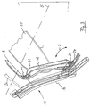
- FIG. 2 illustrates the expedient design of the connection between the middle part 8 and the respective side parts 9 and 10 as a joint part 11, which in the embodiment shown is provided as a spring hinge 12, which is one Distance A spanned between the middle part 8 and the side part 10.
- the side parts 9 and 10 are each provided with a positive control 13, so that when the convertible top tensioning bracket 4 (FIG. 3) moves, the two side parts 9 and 10 during the pivoting movement simultaneously to the central longitudinal plane of the Vehicle can be moved.
- This movement is illustrated by a pivot angle 14, which in principle illustrates a pivot path corresponding to the displacement of the longitudinal axes E-E 'of the side parts 9 and 10 (FIG. 2).
- the top view according to FIG. 2 also illustrates a possible embodiment of the positive control 13, which in the area of a two-part main column 15 in the vicinity of its seal carrier part 16 has a rotatable support part 17 with a connecting strut 18.
- the seal carrier part 16, on the other hand, is connected to the side part 10 in an expedient embodiment via a ball joint 19 which has a plurality of individual parts which are not described in detail.
- the middle part 8 has a second connecting strut 21 which is connected to the connecting strut 18 via a joint 22.
- the positive control 13 is provided with a pendulum support 23 which, together with an extension part 24 provided on the side part 10, acts on the ball joint 19.
- the width B (FIG. 2) of the top fabric tensioning bracket 4 can be reduced, the positive control 13 during a pivoting movement S (FIG. 3) is effective and the respective side part 9 or 10 is moved in accordance with the direction of the arrow (pivot angle 14) in FIG.
- a rear window 25, a corner bow 26 and a drive cylinder 27 are also illustrated in the representations according to FIGS. 1 to 4.
Landscapes
- Engineering & Computer Science (AREA)
- Mechanical Engineering (AREA)
- Body Structure For Vehicles (AREA)
- Tents Or Canopies (AREA)
- Superstructure Of Vehicle (AREA)
Abstract
Description
Die Erfindung bezieht sich auf ein Faltverdeck für ein Cabriolet-Fahrzeug nach dem Oberbegriff des Anspruches 1.The invention relates to a folding top for a convertible vehicle according to the preamble of claim 1.
Bei bekannten Cabriolet-Fahrzeugen dieser Art (z.B. DE 44 38 253 C1) weist das Faltverdeck einen mit dessen Dachhaut verbundenen Verdeckstoffspannbügel auf, der in seiner Längsrichtung im wesentlichen der Dachhautkontur im heckseitigen Bereich folgt. Bei einer Ausbildung des Faltverdecks als ein in eine Verdeckwanne absenkbares Bauteil ist eine dem Verdeckstoffspannbügel entsprechende Mindestgröße für eine Aufnahmeöffnung der Verdeckwanne vorgesehen und damit insgesamt ein entsprechend platzaufwendiger Bewegungsraum in der Fahrzeugkarosserie erforderlich.In known convertible vehicles of this type (e.g. DE 44 38 253 C1), the folding top has a top fabric tensioning bracket connected to its roof skin, which in its longitudinal direction essentially follows the roof skin contour in the rear area. If the folding top is designed as a component that can be lowered into a top trough, a minimum size corresponding to the top fabric tensioning bracket is provided for a receiving opening of the top trough and thus overall a correspondingly space-consuming movement space in the vehicle body is required.
Bei dem erfindungsgemäß ausgebildeten Faltverdeck ist der Verdeckstoffspannbügel als eine mehrteilige Baugruppe ausgebildet, so daß über jeweilige Verbindungsglieder zum am Verdeckstoffspannbügel angreifenden Verdeckantrieb hin eine Zwangssteuerung der Einzelteile des Verdeckstoffspannbügels möglich ist. Damit kann die Breite des Verdeckstoffspannbügels während der Bewegung des Faltverdeckes, beispielsweise beim Absenken in eine Verdeckwanne, zumindest phasenweise so verringert werden, daß auch unter beengten Platzverhältnissen eine ungehinderte Bewegung der Faltverdeckteile über einen großen Schwenkwinkel möglich und in der Faltstellung eine raumsparende Packungsdichte erreicht ist.In the folding top designed according to the invention, the convertible top tensioning bracket is designed as a multi-part assembly, so that positive control of the individual parts of the convertible top tensioning bracket is possible via respective connecting links to the convertible top drive acting on the convertible top tensioning bracket. This means that the width of the convertible top tensioning bracket during the movement of the folding top, for example when lowering into a convertible top trough, at least in phases so that an unimpeded movement of the folding top parts over a large swivel angle is possible even in confined spaces and a space-saving packing density is achieved in the folded position.
Über die zwangsgesteuerte Bewegung der Einzelteile des Verdeckstoffspannbügels ist mit geringem Aufwand auch eine bereichsweise Spannung bzw. Entspannung der Dachhaut möglich, so daß unbeabsichtigte Längungen oder Überdehnungen des Verdeckstoffes vermieden sind und der im Bereich der Heckscheibe vorgesehene Dachhautbereich an eine Vergrößerung der Scheibenfläche anpaßbar ist.The force-controlled movement of the individual parts of the top fabric tensioning bracket also enables a partial tensioning or relaxation of the roof skin with little effort, so that unintentional elongations or overexpansions of the top fabric are avoided and the roof skin area provided in the area of the rear window can be adapted to an increase in the window area.
In der nachfolgenden Beschreibung wird anhand der Zeichnung ein Ausführungsbeispiel eines erfindungsgemäß ausgebildeten Faltverdecks schematisch veranschaulicht. In der Zeichnung zeigen:
- Fig. 1
- eine perspektivische Gesamtansicht eines Faltverdecks ohne Dachhaut,
- Fig. 2
- eine vergrößerte Ausschnittsdarstellung des seitlichen Heckbereichs des Faltverdecks in Draufsicht,
- Fig. 3
- eine Auschnittsdarstellung des Faltverdecks mit einem entgegen der Fahrtrichtung verschwenkten Verdeckstoffspannbügel, und
- Fig. 4
- eine vergrößerte Ausschnittsdarstellung des Verdeckstoffspannbügels in mehrteiliger Ausführung im Bereich zwischen einem Mittelteil und einem Seitenteil.
- Fig. 1
- an overall perspective view of a folding top without a roof skin,
- Fig. 2
- 2 shows an enlarged sectional view of the side rear area of the folding top in plan view,
- Fig. 3
- a sectional view of the folding top with a convertible top fabric bracket pivoted against the direction of travel, and
- Fig. 4
- an enlarged sectional view of the top fabric tensioning bracket in a multi-part design in the area between a central part and a side part.
In Fig. 1 ist eine insgesamt mit 1 bezeichnete Faltverdeck-Baugruppe (ohne Dachhaut) für ein Cabriolet-Fahrzeug veranschaulicht, wobei ein randseitige Verdeckgestellteile 2 und 3 aufweisendes Verdeckgestell im heckseitigen Endbereich mit einem Verdeckstoffspannbügel 4 zusammenwirkt, der gemeinsam mit den Einzelbauteilen des Verdeckgestells im Bereich von jeweils symmetrisch zur Fahrzeuglängsachse 5 angeordneten Hauptschwenklagern 6 und 7 abgestützt ist.In Fig. 1, a folding top assembly (generally designated 1) (without roof skin) for a convertible vehicle is illustrated, with a
Der Verdeckstoffspannbügel 4 ist mehrteilig ausgebildet, wobei dieser in zweckmäßiger Ausführung einen Mittelteil 8 und symmetrisch zu diesem angeordnete Seitenteile 9 und 10 aufweist. Ebenso ist denkbar, den Verdeckstoffspannbügel zweiteilig auszubilden oder weitere Unterteilungen des Mittelteils 8 und/oder der Seitenteile 9 und 10 vorzusehen (nicht dargestellt), so daß weitere einzeln bewegbare Glieder gebildet sind.The convertible
Die Draufsicht gemäß Fig. 2 verdeutlicht in Zusammenschau mit Fig. 4 die zweckmäßige Ausbildung der Verbindung zwischen dem Mittelteil 8 und den jeweiligen Seitenteilen 9 bzw. 10 als ein Gelenkteil 11, wobei dieses in der dargestellten Ausführungsform als ein Federscharnier 12 vorgesehen ist, das einen Abstand A zwischen dem Mittelteil 8 und dem Seitenteil 10 überspannt.The top view according to FIG. 2, in conjunction with FIG. 4, illustrates the expedient design of the connection between the
Im endseitigen Bereich zum jeweiligen Hauptschwenklager 6 bzw. 7 hin sind die Seitenteile 9 bzw. 10 jeweils mit einer Zwangssteuerung 13 versehen, so daß bei Bewegung des Verdeckstoffspannbügels 4 (Fig. 3) die beiden Seitenteile 9 und 10 während der Schwenkbewegung gleichzeitig zur Mittellängsebene des Fahrzeugs hin bewegt werden können. Veranschaulicht ist diese Bewegung durch einen Schwenkwinkel 14, der einen der Verschiebung der Längsachsen E-E' der Seitenteile 9 und 10 entsprechenden Schwenkweg prinzipiell verdeutlicht (Fig. 2).In the end area to the respective main pivot bearing 6 and 7, the
Die Draufsicht gemäß Fig. 2 verdeutlicht außerdem eine mögliche Ausführungsform der Zwangssteuerung 13, die im Bereich einer zweigeteilten Hauptsäule 15 im Nahbereich zu deren Dichtungsträgerteil 16 ein dieses drehbar aufnehmendes Stützteil 17 mit einer Verbindungsstrebe 18 aufweist. Das Dichtungsträgerteil 16 ist andererseits mit dem Seitenteil 10 in zweckmäßiger Ausführung über ein mehrere nicht näher beschriebene Einzelteile aufweisendes Kugelgelenk 19 verbunden.The top view according to FIG. 2 also illustrates a possible embodiment of the
Das Mittelteil 8 weist eine zweite Verbindungsstrebe 21 auf, die mit der Verbindungsstrebe 18 über ein Gelenk 22 verbunden ist. Im Nahbereich zu diesem Gelenk 22 ist die Zwangssteuerung 13 mit einer Pendelstütze 23 versehen, die gemeinsam mit einem am Seitenteil 10 vorgesehenen Auslegerteil 24 am Kugelgelenk 19 angreift.The
Mit dieser Bauteilkombination kann die Breite B (Fig. 2) des Verdeckstoffspannbügels 4 verringert werden, wobei die Zwangssteuerung 13 während einer Schwenkbewegung S (Fig. 3) wirksam ist und über die Pendelstütze 23 und das Auslegerteil 24 das jeweilige Seitenteil 9 bzw. 10 entsprechend der Pfeilrichtung (Schwenkwinkel 14) in Fig. 2 zur Mittellängsachse 5 hin bewegt wird.With this combination of components, the width B (FIG. 2) of the top
In den Darstellungen gemäß Fig. 1 bis Fig. 4 sind außerdem eine Heckscheibe 25, ein Eckspriegel 26 und ein Antriebszylinder 27 verdeutlicht.A
Claims (4)
Applications Claiming Priority (2)
| Application Number | Priority Date | Filing Date | Title |
|---|---|---|---|
| DE19618296A DE19618296C1 (en) | 1996-05-07 | 1996-05-07 | Folding hood for cabriolet vehicle |
| DE19618296 | 1996-05-07 |
Publications (3)
| Publication Number | Publication Date |
|---|---|
| EP0806312A2 true EP0806312A2 (en) | 1997-11-12 |
| EP0806312A3 EP0806312A3 (en) | 1998-07-08 |
| EP0806312B1 EP0806312B1 (en) | 2002-12-04 |
Family
ID=7793585
Family Applications (1)
| Application Number | Title | Priority Date | Filing Date |
|---|---|---|---|
| EP97103396A Expired - Lifetime EP0806312B1 (en) | 1996-05-07 | 1997-03-01 | Foldable top for convertible vehicle |
Country Status (2)
| Country | Link |
|---|---|
| EP (1) | EP0806312B1 (en) |
| DE (2) | DE19618296C1 (en) |
Cited By (1)
| Publication number | Priority date | Publication date | Assignee | Title |
|---|---|---|---|---|
| DE10029473A1 (en) * | 2000-06-15 | 2002-01-03 | Karmann Gmbh W | Convertible car |
Families Citing this family (10)
| Publication number | Priority date | Publication date | Assignee | Title |
|---|---|---|---|---|
| DE19911541B4 (en) * | 1998-11-14 | 2004-05-19 | Cts Fahrzeug-Dachsysteme Gmbh | Folding hood for a motor vehicle |
| DE19930774C1 (en) * | 1999-07-03 | 2000-11-09 | Cts Fahrzeug Dachsysteme Gmbh | Opening roof for convertible or cabriolet vehicle has rearmost frame element of roof support frame displaced in direction of passenger space in translatory horizontal movement plane when roof is opened |
| DE19942427B4 (en) * | 1999-09-06 | 2006-11-09 | Webasto Ag | Folding hood for a convertible |
| DE19962377C1 (en) * | 1999-12-23 | 2001-07-05 | Cts Fahrzeug Dachsysteme Gmbh | Adjustable vehicle roof has folding cover adjustable between closed position and folded position, with cover bar and covering material piece |
| DE20010642U1 (en) * | 2000-06-15 | 2001-10-25 | Wilhelm Karmann GmbH, 49084 Osnabrück | Cabriolet vehicle |
| DE102004042623A1 (en) * | 2003-09-01 | 2005-05-04 | Karmann Gmbh W | Cabriolet vehicle comprises a connection formed between side parts and a middle part so that it pivots on the side parts from a first position into a second position |
| DE102005001871A1 (en) * | 2005-01-14 | 2006-07-20 | Bayerische Motoren Werke Ag | Adjustable tensioning bracket for folding roof of motor vehicle has base section which is connected with side areas and supports laterally opposite lying tensioning elements |
| DE102005034310A1 (en) | 2005-07-22 | 2007-01-25 | Wilhelm Karmann Gmbh | Convertible car |
| DE102005045213B4 (en) * | 2005-09-21 | 2007-11-08 | Webasto Ag | Folding hood of a motor vehicle |
| DE102009022818A1 (en) | 2009-05-27 | 2010-12-02 | Dr. Ing. H.C. F. Porsche Aktiengesellschaft | Roof structure for cabriolet vehicle, has hinge connections formed between tensioning bow holder and folding-top and between tensioning bow holder and ends of tensioning bow that comprises joint |
Family Cites Families (2)
| Publication number | Priority date | Publication date | Assignee | Title |
|---|---|---|---|---|
| DE2327486C2 (en) * | 1973-05-30 | 1975-04-30 | Daimler-Benz Ag, 7000 Stuttgart | Control of a linkage of a folding top of motor vehicles that is hinged to sunk-in consoles |
| DE4438253C1 (en) * | 1994-10-26 | 1995-10-26 | Porsche Ag | Folding hood for a vehicle, in particular a passenger car |
-
1996
- 1996-05-07 DE DE19618296A patent/DE19618296C1/en not_active Expired - Fee Related
-
1997
- 1997-03-01 DE DE59708860T patent/DE59708860D1/en not_active Expired - Lifetime
- 1997-03-01 EP EP97103396A patent/EP0806312B1/en not_active Expired - Lifetime
Cited By (2)
| Publication number | Priority date | Publication date | Assignee | Title |
|---|---|---|---|---|
| DE10029473A1 (en) * | 2000-06-15 | 2002-01-03 | Karmann Gmbh W | Convertible car |
| DE10029473B4 (en) * | 2000-06-15 | 2006-09-07 | Wilhelm Karmann Gmbh | Convertible car |
Also Published As
| Publication number | Publication date |
|---|---|
| DE19618296C1 (en) | 1997-08-28 |
| EP0806312B1 (en) | 2002-12-04 |
| DE59708860D1 (en) | 2003-01-16 |
| EP0806312A3 (en) | 1998-07-08 |
Similar Documents
| Publication | Publication Date | Title |
|---|---|---|
| EP0811518B1 (en) | Vehicle, particularly with foldable roof | |
| EP0521307B2 (en) | Folding hood for motorvehicle provided with a collapsible roof | |
| DE10063152B4 (en) | Folding roof cars | |
| EP1164041B1 (en) | Convertible vehicle | |
| DE69904108T2 (en) | Folding roof in three parts for convertible vehicles | |
| DE3405920C2 (en) | Folding roofs for vehicles, in particular for passenger cars | |
| DE10050286A1 (en) | Multi-part cover for vehicles | |
| EP0760301B1 (en) | Foldable top for convertible vehicle | |
| DE4316485A1 (en) | Folding top for motor vehicles | |
| DE4446483A1 (en) | Convertible car with tonneau roof construction | |
| EP0922597A1 (en) | Vehicle provided with a retractable roof structure | |
| EP0648630A1 (en) | Foldable top for convertible | |
| DE10008492A1 (en) | Folding hood for a motor vehicle | |
| DE19618296C1 (en) | Folding hood for cabriolet vehicle | |
| EP1067000B1 (en) | Movable vehicle roof | |
| DE19737349A1 (en) | Hardtop vehicle | |
| EP0879722B1 (en) | Convertible soft top for passenger motor vehicle | |
| EP0885760B1 (en) | Convertible for motorvehicle | |
| EP0819558B1 (en) | Convertible vehicle with a foldable top | |
| DE9307481U1 (en) | Folding roof for motor vehicles | |
| DE19610969C2 (en) | Folding roof for passenger cars | |
| EP1164039B1 (en) | Convertible vehicle | |
| EP0952022B1 (en) | Foldable top for convertible vehicles | |
| DE9206807U1 (en) | FOLDING COVER FOR A PERSONAL VEHICLE WITH FOLDING ROOF | |
| EP1995100B1 (en) | Collapsible roof for a convertible |
Legal Events
| Date | Code | Title | Description |
|---|---|---|---|
| PUAI | Public reference made under article 153(3) epc to a published international application that has entered the european phase |
Free format text: ORIGINAL CODE: 0009012 |
|
| AK | Designated contracting states |
Kind code of ref document: A2 Designated state(s): DE FI FR GB IT SE |
|
| PUAL | Search report despatched |
Free format text: ORIGINAL CODE: 0009013 |
|
| AK | Designated contracting states |
Kind code of ref document: A3 Designated state(s): DE FI FR GB IT SE |
|
| 17P | Request for examination filed |
Effective date: 19980807 |
|
| GRAG | Despatch of communication of intention to grant |
Free format text: ORIGINAL CODE: EPIDOS AGRA |
|
| GRAG | Despatch of communication of intention to grant |
Free format text: ORIGINAL CODE: EPIDOS AGRA |
|
| GRAH | Despatch of communication of intention to grant a patent |
Free format text: ORIGINAL CODE: EPIDOS IGRA |
|
| 17Q | First examination report despatched |
Effective date: 20020605 |
|
| GRAH | Despatch of communication of intention to grant a patent |
Free format text: ORIGINAL CODE: EPIDOS IGRA |
|
| GRAA | (expected) grant |
Free format text: ORIGINAL CODE: 0009210 |
|
| AK | Designated contracting states |
Kind code of ref document: B1 Designated state(s): DE FI FR GB IT SE |
|
| PG25 | Lapsed in a contracting state [announced via postgrant information from national office to epo] |
Ref country code: FI Free format text: LAPSE BECAUSE OF FAILURE TO SUBMIT A TRANSLATION OF THE DESCRIPTION OR TO PAY THE FEE WITHIN THE PRESCRIBED TIME-LIMIT Effective date: 20021204 |
|
| REG | Reference to a national code |
Ref country code: GB Ref legal event code: FG4D Free format text: NOT ENGLISH |
|
| GBT | Gb: translation of ep patent filed (gb section 77(6)(a)/1977) |
Effective date: 20021209 |
|
| REF | Corresponds to: |
Ref document number: 59708860 Country of ref document: DE Date of ref document: 20030116 |
|
| PG25 | Lapsed in a contracting state [announced via postgrant information from national office to epo] |
Ref country code: SE Free format text: LAPSE BECAUSE OF FAILURE TO SUBMIT A TRANSLATION OF THE DESCRIPTION OR TO PAY THE FEE WITHIN THE PRESCRIBED TIME-LIMIT Effective date: 20030304 |
|
| ET | Fr: translation filed | ||
| PLBE | No opposition filed within time limit |
Free format text: ORIGINAL CODE: 0009261 |
|
| STAA | Information on the status of an ep patent application or granted ep patent |
Free format text: STATUS: NO OPPOSITION FILED WITHIN TIME LIMIT |
|
| 26N | No opposition filed |
Effective date: 20030905 |
|
| PGFP | Annual fee paid to national office [announced via postgrant information from national office to epo] |
Ref country code: SE Payment date: 20040326 Year of fee payment: 8 |
|
| PGFP | Annual fee paid to national office [announced via postgrant information from national office to epo] |
Ref country code: IT Payment date: 20100313 Year of fee payment: 14 Ref country code: FR Payment date: 20100324 Year of fee payment: 14 |
|
| PGFP | Annual fee paid to national office [announced via postgrant information from national office to epo] |
Ref country code: GB Payment date: 20100224 Year of fee payment: 14 |
|
| PGFP | Annual fee paid to national office [announced via postgrant information from national office to epo] |
Ref country code: DE Payment date: 20100312 Year of fee payment: 14 |
|
| GBPC | Gb: european patent ceased through non-payment of renewal fee |
Effective date: 20110301 |
|
| REG | Reference to a national code |
Ref country code: FR Ref legal event code: ST Effective date: 20111130 |
|
| PG25 | Lapsed in a contracting state [announced via postgrant information from national office to epo] |
Ref country code: DE Free format text: LAPSE BECAUSE OF NON-PAYMENT OF DUE FEES Effective date: 20111001 Ref country code: FR Free format text: LAPSE BECAUSE OF NON-PAYMENT OF DUE FEES Effective date: 20110331 |
|
| PG25 | Lapsed in a contracting state [announced via postgrant information from national office to epo] |
Ref country code: IT Free format text: LAPSE BECAUSE OF NON-PAYMENT OF DUE FEES Effective date: 20110301 Ref country code: GB Free format text: LAPSE BECAUSE OF NON-PAYMENT OF DUE FEES Effective date: 20110301 |
|
| REG | Reference to a national code |
Ref country code: DE Ref legal event code: R119 Ref document number: 59708860 Country of ref document: DE Effective date: 20111001 |