EP0806153B1 - Tank and process for heat treatment of packages comprising food material - Google Patents
Tank and process for heat treatment of packages comprising food material Download PDFInfo
- Publication number
- EP0806153B1 EP0806153B1 EP96201249A EP96201249A EP0806153B1 EP 0806153 B1 EP0806153 B1 EP 0806153B1 EP 96201249 A EP96201249 A EP 96201249A EP 96201249 A EP96201249 A EP 96201249A EP 0806153 B1 EP0806153 B1 EP 0806153B1
- Authority
- EP
- European Patent Office
- Prior art keywords
- tank
- packages
- roller
- band
- substantially stationary
- Prior art date
- Legal status (The legal status is an assumption and is not a legal conclusion. Google has not performed a legal analysis and makes no representation as to the accuracy of the status listed.)
- Expired - Lifetime
Links
- 238000010438 heat treatment Methods 0.000 title abstract description 25
- 235000013305 food Nutrition 0.000 title abstract description 11
- 239000000463 material Substances 0.000 title abstract description 11
- 238000000034 method Methods 0.000 title abstract description 9
- XLYOFNOQVPJJNP-UHFFFAOYSA-N water Substances O XLYOFNOQVPJJNP-UHFFFAOYSA-N 0.000 description 25
- 238000000926 separation method Methods 0.000 description 4
- 238000012856 packing Methods 0.000 description 3
- 239000000047 product Substances 0.000 description 3
- 230000003313 weakening effect Effects 0.000 description 3
- 238000009835 boiling Methods 0.000 description 2
- 239000011888 foil Substances 0.000 description 2
- 230000001939 inductive effect Effects 0.000 description 2
- 239000012263 liquid product Substances 0.000 description 2
- 238000004806 packaging method and process Methods 0.000 description 2
- -1 polyethylene Polymers 0.000 description 2
- 230000002028 premature Effects 0.000 description 2
- 238000004659 sterilization and disinfection Methods 0.000 description 2
- 230000003319 supportive effect Effects 0.000 description 2
- 241000168096 Glareolidae Species 0.000 description 1
- 239000004698 Polyethylene Substances 0.000 description 1
- 239000004743 Polypropylene Substances 0.000 description 1
- 238000010924 continuous production Methods 0.000 description 1
- 238000010411 cooking Methods 0.000 description 1
- 238000005520 cutting process Methods 0.000 description 1
- 230000001419 dependent effect Effects 0.000 description 1
- 230000000694 effects Effects 0.000 description 1
- 230000008030 elimination Effects 0.000 description 1
- 238000003379 elimination reaction Methods 0.000 description 1
- 238000009499 grossing Methods 0.000 description 1
- 238000007373 indentation Methods 0.000 description 1
- 230000006698 induction Effects 0.000 description 1
- 230000002045 lasting effect Effects 0.000 description 1
- 239000007788 liquid Substances 0.000 description 1
- 238000004519 manufacturing process Methods 0.000 description 1
- 239000011159 matrix material Substances 0.000 description 1
- 230000002906 microbiologic effect Effects 0.000 description 1
- 230000010355 oscillation Effects 0.000 description 1
- 239000005022 packaging material Substances 0.000 description 1
- 235000021485 packed food Nutrition 0.000 description 1
- 238000009928 pasteurization Methods 0.000 description 1
- 239000002985 plastic film Substances 0.000 description 1
- 229920006255 plastic film Polymers 0.000 description 1
- 229920000573 polyethylene Polymers 0.000 description 1
- 229920001155 polypropylene Polymers 0.000 description 1
- 230000001105 regulatory effect Effects 0.000 description 1
- 230000000630 rising effect Effects 0.000 description 1
- 238000007789 sealing Methods 0.000 description 1
- 238000003466 welding Methods 0.000 description 1
Images


Classifications
-
- A—HUMAN NECESSITIES
- A23—FOODS OR FOODSTUFFS; TREATMENT THEREOF, NOT COVERED BY OTHER CLASSES
- A23B—PRESERVATION OF FOODS, FOODSTUFFS OR NON-ALCOHOLIC BEVERAGES; CHEMICAL RIPENING OF FRUIT OR VEGETABLES
- A23B2/00—Preservation of foods or foodstuffs, in general
- A23B2/20—Preservation of foods or foodstuffs, in general by heating materials in packages which are progressively transported, continuously or stepwise, through the apparatus
- A23B2/22—Preservation of foods or foodstuffs, in general by heating materials in packages which are progressively transported, continuously or stepwise, through the apparatus with packages on endless chain or band conveyors
-
- A—HUMAN NECESSITIES
- A23—FOODS OR FOODSTUFFS; TREATMENT THEREOF, NOT COVERED BY OTHER CLASSES
- A23B—PRESERVATION OF FOODS, FOODSTUFFS OR NON-ALCOHOLIC BEVERAGES; CHEMICAL RIPENING OF FRUIT OR VEGETABLES
- A23B2/00—Preservation of foods or foodstuffs, in general
- A23B2/20—Preservation of foods or foodstuffs, in general by heating materials in packages which are progressively transported, continuously or stepwise, through the apparatus
-
- B—PERFORMING OPERATIONS; TRANSPORTING
- B65—CONVEYING; PACKING; STORING; HANDLING THIN OR FILAMENTARY MATERIAL
- B65H—HANDLING THIN OR FILAMENTARY MATERIAL, e.g. SHEETS, WEBS, CABLES
- B65H20/00—Advancing webs
- B65H20/30—Arrangements for accumulating surplus web
- B65H20/32—Arrangements for accumulating surplus web by making loops
- B65H20/34—Arrangements for accumulating surplus web by making loops with rollers
-
- B—PERFORMING OPERATIONS; TRANSPORTING
- B65—CONVEYING; PACKING; STORING; HANDLING THIN OR FILAMENTARY MATERIAL
- B65H—HANDLING THIN OR FILAMENTARY MATERIAL, e.g. SHEETS, WEBS, CABLES
- B65H2511/00—Dimensions; Position; Numbers; Identification; Occurrences
- B65H2511/20—Location in space
- B65H2511/22—Distance
-
- B—PERFORMING OPERATIONS; TRANSPORTING
- B65—CONVEYING; PACKING; STORING; HANDLING THIN OR FILAMENTARY MATERIAL
- B65H—HANDLING THIN OR FILAMENTARY MATERIAL, e.g. SHEETS, WEBS, CABLES
- B65H2513/00—Dynamic entities; Timing aspects
- B65H2513/10—Speed
-
- B—PERFORMING OPERATIONS; TRANSPORTING
- B65—CONVEYING; PACKING; STORING; HANDLING THIN OR FILAMENTARY MATERIAL
- B65H—HANDLING THIN OR FILAMENTARY MATERIAL, e.g. SHEETS, WEBS, CABLES
- B65H2515/00—Physical entities not provided for in groups B65H2511/00 or B65H2513/00
- B65H2515/30—Forces; Stresses
- B65H2515/31—Tensile forces
Definitions
- the present invention relates to a process and a tank for heat treatment of bands of packages.
- the invention also relates to the use of a tank for heat treatment of bands of packages containing food material.
- Heat treatment such as in-pack pasteurising or sterilisation of packages containing food product are used in the food industry for the reduction of micro biologic activity in the food product and to increase the life of the product.
- Such an in-pack heat treatment takes place once the product is sealed off within the package.
- the product to be heat treated is packed in individually separate packages.
- Continuous packaging machines such as MultivacTM and Flowwrap machines are used in the production of separate individual packages which are not joined together.
- packages are shaped from film or foil, then filled, sealed and cut to release the package from packaging material supply.
- the package is then ejected from the packaging machine and transported to the heat treatment apparatus.
- the separation of the individual packages from abutting packing material is carried out while the package is in the machine, e.g. at the same time as the sealing of the package as its position is then well defined.
- U.S. Patent 3,464,835 relates to a process for pasteurizing liquid products comprising a succession of sachets of flexible material in an uninterrupted line, the process comprising the operation of passing the line of sachets along an undulating path of travel in successive treatment zones by exerting traction on the line of sachets, and circulating a treatment liquid in the treatment zones to cause the liquid product in the sachets to be heated and undergo pasteurization treatment as the sachets pass through the zones.
- the invention relates to a tank for heat treatment of packages comprising food material attached to one another in a band, said tank comprises at least one substantially stationary roller and at least one movable roller capable of being moved reciprocally vertically from a position above to a position below the substantially stationary roller.
- the band of packages is self supportive, acts as its own conveyor and is trained below and above the rollers in a zigzag course.
- the zigzag course allows for a compact design of the tank.
- the tank is filled with hot or boiling water and means for heating the water is provided.
- Heat treatment by passing the packages through water gives, as described above, a good heat transfer due to the direct contact between the package and the water.
- the water heating may also give longer lasting package weldings than what can be obtained when heating a package in hot air.
- the hot air expansion of the content of the package results in a temporary deformation of the package.
- the heat treatment in water further has the advantage of substantially eliminating the weight of the packages while they are being transported through the water. This allows the band to be trained vertically without any risk of breakage of band or package.
- the tank according to the invention is suitable for in-pack heat treatment such as pasteurising, sterilisation and cooking of food products in packages in bands.
- the packages may e.g. be in form of a tray with sealed lids or pouches, the packages being joined so as to form a band of packages.
- the band may conveniently be e.g. a single column of packages or a matrix of rows of two or more packages attached to one another.
- Materials suitable for such packages are plastic film or foil, e.g. polyethylene, polypropylene etc.
- the walls of the tank are conveniently provided with guiding means which are adapted to guide the shafts of the movable rollers as they reciprocate. Means may be provided to adjust the lower end position of the movable roller to the desired heat treatment time by thus adjusting the length of the course through the hot water.
- the substantially stationary roller and/or the movable roller are/is provided with indentations for the engagement with a package while it is being trained around the roller.
- the substantially stationary roller and/or the movable roller are/is provided with projections along its periphery.
- the band of packages may be provided with openings in rim areas on both sides of the band for the engagement with said projections.
- weakening lines are provided between the packages. Due to the sensitive control system it is possible to control the stretching of the band and thus prevent any premature tearing of the band. Furthermore, such weakening lines makes it easy to separate the packages without need for precise orientation and fixation of the packages such as is needed for separation by cutting.
- the tank is provided with a control system to ensure a stretching of the band of packages without any premature separation of the packages.
- the control system comprises the substantially stationary roller having a density less than 1.0 which is guided to allow a certain small movement upwards and downwards, and at least one sensor device adapted to automatically adjust the speed of the bands of packages, depending on the position of the substantially stationary roller. It follows from the density of the roller that it is floatable in water and thus will provide a slight upward pressure upon the band of packages.
- the tank may be positioned subsequent to the packing machine producing the band of packages, in such a case the speed of the band in the tank can be adjusted by adjusting the speed of the packages ejected from it.
- the control system may be digital or analogous.
- an inductive sensor is adapted to detect the position of a substantially stationary roller.
- the sensor may be positioned in at least one groove guiding the shaft whereas in an analogous control system an analogous sensor measures the rotation of a wheel which is connected to a roller by means of a taut wire.
- the tank is conveniently provided with inlet and outlet means for the band in the side wall, preferably at a position between the stationary rollers and the movable rollers when in their upper position. Due to the packages floating ability the band is conveniently drawn across the tank between the stationary rollers and the movable rollers. These movable rollers subsequently reciprocate from their upper position to their lower position after which the continuous process of heat treating the band during its course through the tank can begin. Outside the tank conveyors or other supports may be provided for the support and transport of the packages to be heat treated.
- the band comprises a leading end wherein no food material is encapsulated. This is to be used for the loading of the band so as to secure that the packed food material is allowed a sufficiently long time in the hot or boiling water for the heat treatment to be adequate.
- the present invention provides a process for heat treating packages comprising food material wherein the packages are attached to one another in a band, said process comprising conveying the band of pouches through a tank by passing the band beneath at least one vertically movable roller and above at least one substantially stationary roller, and moving the movable roller downwards to a position below the substantially stationary roller to cause the band to travel in a substantially vertical zigzag course through the water.
- the invention also relates to the use of the tank for heat treatment of a band of packages.
- a tank 16 for heat treatment of band 13 of packages 40 is shown in Fig. 1.
- the tank 16 containing water 17, a steam coil 18, substantially stationary rollers 19, 32 with shafts 20, capable of sliding in vertical grooves 21 (Fig 8), movable rollers 22 with shafts 23 fixed in threaded nuts 34 capable of reciprocating along threaded spindles 24 (Figs. 5 and 6) fixed to a wall of the tank by bearings 35 and which are rotated by an electric motor 25.
- the tank 16 is provided with an inlet 26 and an outlet 27 and beyond the outlet is an outlet conveyor 28.
- Fig. 7, 8 and 9 show an inductive sensor 30 in the vertical groove 21 close to the end of the shaft 20 of a stationary roller 32 with a speed regulator 33 for adjusting the speed of feed conveyor 15.
- Figs. 10, 11, and 12 show a wire 36 connecting the shaft 20 of roller 32 to a wheel 37 attached to an analogous sensor 38 with a torsion spring 39 to taut the wire 36.
- the movable rollers 22 in the tank 16 are in their upper position as shown in Fig. 1, and the leading end of the band 13 without packages is guided along the inlet conveyor 15 through the inlet 26 above the water surface in the tank 16, through the outlet 27 and placed on the outlet conveyor 28 which is stationary.
- the electric motor 25 is then switched on to rotate the threaded spindles 25.
- the outlet conveyor is started at the desired running speed. If a shorter heat treatment time is required, it is possible to raise the movable rollers 22 from their lower position shown in Fig. 2 to any desired position, which results in a shorter courser of the band 13 of packages 40 through the tank 16.
- a control system is provided to ensure a controlled stretching in order to prevent an over stretching of the band of packages and thus minimising the risk for breakage of the band along weakening lines between the packages while it is travelling through the water.
- Said control system comprises an induction sensor 30 shown in Figs. 4, 7, 8 and 9 and an analogous sensor 38 which is shown in Figs. 10, 11 and 12 where the substantially stationary rollers 19, 32 are designed to have a density below 1.0, resulting in a tendency of rising in the water-filled tank 16.
- the roller shafts 20 are guided in vertical grooves 21 which allow a certain movement upwards and downwards.
- the rollers 32 are in embodiments illustrated designed to have a slightly higher density than the other rollers 19 so that if the band of packages becomes stretched, roller 32 will descend before roller 19.
- Roller 19 function as an extra safety device to prevent the band from breaking at extremely fast tension.
- the indication roller 32 when in its upper position actuates the sensor 30 which gives a signal to the speed regulator 33 to control the speed of the feed conveyor 15.
- the band of packages travels above the rollers 19 and the indication roller 32 and when the outlet conveyor 28 pulls the band too much, the indication roller which is floating in the water will be pressed downwards before the roller 19 because of its higher density, and will descend until a certain level, at which it ceases actuating sensor 30.
- This sensor then interrupts its signal to the speed regulator 33 of the feed conveyor 15, which increases its speed until it reaches a pre-determined speed, higher than the speed of the outlet conveyor 28 and until the tension of the band of packages is released.
- the indication roller 32 will then ascend to a higher level, thereby actuating sensor 30 again, and this in turn gives a signal to the speed regulator 33 to decrease the speed of the feed conveyor to a lower, pre-determined speed.
- the indication roller 32 which is floating in the water, will thus be oscillating around the level "sensor actuated/not actuated”. The duration of the oscillation is dependent on the inertia of the speed regulator of the inlet conveyor and on how the indication roller ascends in the water.
- the system is thus based on a fixed speed, "v" of the outlet conveyor 28 placed beyond the outlet 27.
- its feeding speed is regulated by reducing or increasing the speed of the feed conveyor 15 by means of the indication roller 32 which is floating in the water.
- the substantially stationary rollers 19, 32 have a smoothing effect on possibly occurring tension of the band 13 of packages 40, as there are also floating in the water, thus being capable of moving a certain distance in a vertical direction.
Landscapes
- Life Sciences & Earth Sciences (AREA)
- Engineering & Computer Science (AREA)
- Wood Science & Technology (AREA)
- Zoology (AREA)
- Chemical & Material Sciences (AREA)
- Food Science & Technology (AREA)
- Polymers & Plastics (AREA)
- Food Preservation Except Freezing, Refrigeration, And Drying (AREA)
- General Preparation And Processing Of Foods (AREA)
- Cookers (AREA)
- Packages (AREA)
- Cereal-Derived Products (AREA)
Abstract
Description
- The present invention relates to a process and a tank for heat treatment of bands of packages. The invention also relates to the use of a tank for heat treatment of bands of packages containing food material.
- Heat treatment such as in-pack pasteurising or sterilisation of packages containing food product are used in the food industry for the reduction of micro biologic activity in the food product and to increase the life of the product. Such an in-pack heat treatment takes place once the product is sealed off within the package.
- Conventionally, the product to be heat treated is packed in individually separate packages. Continuous packaging machines such as Multivac™ and Flowwrap machines are used in the production of separate individual packages which are not joined together. In these machines packages are shaped from film or foil, then filled, sealed and cut to release the package from packaging material supply. The package is then ejected from the packaging machine and transported to the heat treatment apparatus. In these continuous packing machines the separation of the individual packages from abutting packing material is carried out while the package is in the machine, e.g. at the same time as the sealing of the package as its position is then well defined.
- It is known to heat treat individually the packed packages in pasteurising tunnels wherein they are subjected to hot air or steam. Such pasteurising tunnels suffer, however, from the serious drawback of being very space demanding. Another possibility is to pasteurise the packages by conveying them through hot water. To do this, it is necessary to hold the packages below surface of the water they will otherwise tend to float due to the air captured in the packages. For example, this is done by means of a conveyor system wherein packages are positioned between two parallel running conveyors or held to a single conveyor by attachment means. To reduce the space required the conveyors advantageously run along zigzag paths. However, conveyor belts are expensive, and easily become worn or broken especially when travelling through hot water.
- U.S. Patent 3,464,835 relates to a process for pasteurizing liquid products comprising a succession of sachets of flexible material in an uninterrupted line, the process comprising the operation of passing the line of sachets along an undulating path of travel in successive treatment zones by exerting traction on the line of sachets, and circulating a treatment liquid in the treatment zones to cause the liquid product in the sachets to be heated and undergo pasteurization treatment as the sachets pass through the zones.
- We have now devised a process and a tank for heat treatment of packages which may be used to overcome the above described problems. In the process and tank according to the invention it has been found that advantages can be obtained if contrary to the normal practice of separating the packages from one another they are kept together in a continuous band of packages and this band acts as its own conveyor. The present invention may have among other things the following advantages:
- Elimination of the need for conveyor belts.
- A compact design.
- Good heat transfer due to the direct contact with the hot medium.
- Less deformation of packages resulting from heating of the content due to the counter pressure of the water.
- Constant stretched band of packages preventing breakage thereof.
- Flexibility to the shape of the heat treated packages.
- Easy loading system.
- Accordingly in a first aspect, the invention relates to a tank for heat treatment of packages comprising food material attached to one another in a band, said tank comprises at least one substantially stationary roller and at least one movable roller capable of being moved reciprocally vertically from a position above to a position below the substantially stationary roller.
- With the present tank for heat treatment the need for supportive conveyors for the transportation and fixation of the package is eliminated. The band of packages is self supportive, acts as its own conveyor and is trained below and above the rollers in a zigzag course. The zigzag course allows for a compact design of the tank.
- For heat treatment, the tank is filled with hot or boiling water and means for heating the water is provided. Heat treatment by passing the packages through water gives, as described above, a good heat transfer due to the direct contact between the package and the water. The water heating may also give longer lasting package weldings than what can be obtained when heating a package in hot air. The hot air expansion of the content of the package results in a temporary deformation of the package. The heat treatment in water further has the advantage of substantially eliminating the weight of the packages while they are being transported through the water. This allows the band to be trained vertically without any risk of breakage of band or package.
- The tank according to the invention is suitable for in-pack heat treatment such as pasteurising, sterilisation and cooking of food products in packages in bands. The packages may e.g. be in form of a tray with sealed lids or pouches, the packages being joined so as to form a band of packages. The band may conveniently be e.g. a single column of packages or a matrix of rows of two or more packages attached to one another. Materials suitable for such packages are plastic film or foil, e.g. polyethylene, polypropylene etc.
- Preferably, there are more than one substantially stationary and movable rollers positioned alternately, all the movable rollers being adapted to ascend or descend simultaneously.
- The walls of the tank are conveniently provided with guiding means which are adapted to guide the shafts of the movable rollers as they reciprocate. Means may be provided to adjust the lower end position of the movable roller to the desired heat treatment time by thus adjusting the length of the course through the hot water.
- In one advantageous embodiment of the invention the substantially stationary roller and/or the movable roller are/is provided with indentations for the engagement with a package while it is being trained around the roller.
- In another advantageous embodiment of the invention the substantially stationary roller and/or the movable roller are/is provided with projections along its periphery. For this embodiment the band of packages may be provided with openings in rim areas on both sides of the band for the engagement with said projections.
- For an easy separation of the package from each other after the end of the heat treatment, weakening lines are provided between the packages. Due to the sensitive control system it is possible to control the stretching of the band and thus prevent any premature tearing of the band. Furthermore, such weakening lines makes it easy to separate the packages without need for precise orientation and fixation of the packages such as is needed for separation by cutting.
- In a preferred embodiment the tank is provided with a control system to ensure a stretching of the band of packages without any premature separation of the packages. The control system comprises the substantially stationary roller having a density less than 1.0 which is guided to allow a certain small movement upwards and downwards, and at least one sensor device adapted to automatically adjust the speed of the bands of packages, depending on the position of the substantially stationary roller. It follows from the density of the roller that it is floatable in water and thus will provide a slight upward pressure upon the band of packages.
- The tank may be positioned subsequent to the packing machine producing the band of packages, in such a case the speed of the band in the tank can be adjusted by adjusting the speed of the packages ejected from it.
- The control system may be digital or analogous. For example, in a digital control system an inductive sensor is adapted to detect the position of a substantially stationary roller. In a digital control system, the sensor may be positioned in at least one groove guiding the shaft whereas in an analogous control system an analogous sensor measures the rotation of a wheel which is connected to a roller by means of a taut wire.
- In order to ease loading of the band of packages the tank is conveniently provided with inlet and outlet means for the band in the side wall, preferably at a position between the stationary rollers and the movable rollers when in their upper position. Due to the packages floating ability the band is conveniently drawn across the tank between the stationary rollers and the movable rollers. These movable rollers subsequently reciprocate from their upper position to their lower position after which the continuous process of heat treating the band during its course through the tank can begin. Outside the tank conveyors or other supports may be provided for the support and transport of the packages to be heat treated.
- It is preferred that the band comprises a leading end wherein no food material is encapsulated. This is to be used for the loading of the band so as to secure that the packed food material is allowed a sufficiently long time in the hot or boiling water for the heat treatment to be adequate.
- In a second aspect, the present invention provides a process for heat treating packages comprising food material wherein the packages are attached to one another in a band, said process comprising conveying the band of pouches through a tank by passing the band beneath at least one vertically movable roller and above at least one substantially stationary roller, and moving the movable roller downwards to a position below the substantially stationary roller to cause the band to travel in a substantially vertical zigzag course through the water.
- The invention also relates to the use of the tank for heat treatment of a band of packages.
- The present invention will now be illustrated by way of example only with reference to the accompanying drawings in which
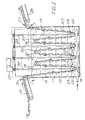
- Fig. 1 is a side sectional view of a tank according to the invention with the movable rollers in their upper position and wherein a band of package is ready to be loaded,
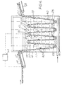
- Fig. 2 is a side sectional view of a tank according to the invention in operation with the movable rollers in their lower position,
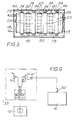
- Fig. 3 is a top view of Fig. 2 looking in the direction of the arrows I-I,
- Fig. 4 is a side sectional view of a tank according to the invention showing a control mechanism.
- Fig. 5 is a sectional view through one of the walls of the tank showing guiding means for the movable roller,
- Fig. 6 is a view of Fig. 5 along the line I-I looking in the direction of the arrows,
- Fig. 7 is a sectional view through a wall of the tank showing detail of a control system,
- Fig. 8 is a view of Fig. 7 along line II-II looking in the direction of the arrows,
- Fig. 9 is a schematic view of the control system,
- Fig. 10 is a sectional view of Fig. 1 along the line III-III looking in the direction of the arrows to show an alternative control mechanism,
- Fig. 11 is a sectional view along the line IV-IV of Fig. 10 looking in the direction of the arrows, and
- Fig. 12 is a schematic view of the alternative control system shown in Figs. 10 and 11.
-
- Referring to the drawings, a
tank 16 for heat treatment ofband 13 ofpackages 40 is shown in Fig. 1. Thetank 16 containingwater 17, asteam coil 18, substantiallystationary rollers shafts 20, capable of sliding in vertical grooves 21 (Fig 8),movable rollers 22 withshafts 23 fixed in threaded nuts 34 capable of reciprocating along threaded spindles 24 (Figs. 5 and 6) fixed to a wall of the tank bybearings 35 and which are rotated by anelectric motor 25. Thetank 16 is provided with aninlet 26 and anoutlet 27 and beyond the outlet is anoutlet conveyor 28. Fig. 7, 8 and 9 show aninductive sensor 30 in thevertical groove 21 close to the end of theshaft 20 of astationary roller 32 with aspeed regulator 33 for adjusting the speed offeed conveyor 15. Figs. 10, 11, and 12, show awire 36 connecting theshaft 20 ofroller 32 to awheel 37 attached to ananalogous sensor 38 with atorsion spring 39 to taut thewire 36. - At the start of the loading, the
movable rollers 22 in thetank 16 are in their upper position as shown in Fig. 1, and the leading end of theband 13 without packages is guided along theinlet conveyor 15 through theinlet 26 above the water surface in thetank 16, through theoutlet 27 and placed on theoutlet conveyor 28 which is stationary. Theelectric motor 25 is then switched on to rotate the threadedspindles 25. This lowers themovable rollers 22, by means of theshafts 23 fixed in the threaded nuts 34 which travel along the threaded spindles slowly into thetank 16 so that they guide theband 13 ofpackages 40 down into the water to travel in a vertical zigzag course underneath themovable rollers 22 and over the substantiallystationary rollers 32. When the movable rollers have reached their lower position as shown in Fig. 2, the outlet conveyor is started at the desired running speed. If a shorter heat treatment time is required, it is possible to raise themovable rollers 22 from their lower position shown in Fig. 2 to any desired position, which results in a shorter courser of theband 13 ofpackages 40 through thetank 16. - A control system is provided to ensure a controlled stretching in order to prevent an over stretching of the band of packages and thus minimising the risk for breakage of the band along weakening lines between the packages while it is travelling through the water. Said control system comprises an
induction sensor 30 shown in Figs. 4, 7, 8 and 9 and ananalogous sensor 38 which is shown in Figs. 10, 11 and 12 where the substantiallystationary rollers tank 16. Theroller shafts 20 are guided invertical grooves 21 which allow a certain movement upwards and downwards. Therollers 32 are in embodiments illustrated designed to have a slightly higher density than theother rollers 19 so that if the band of packages becomes stretched,roller 32 will descend beforeroller 19.Roller 19 function as an extra safety device to prevent the band from breaking at extremely fast tension. In the embodiment illustrated in Figs. 4, 7, 8 and 9, theindication roller 32 when in its upper position actuates thesensor 30 which gives a signal to thespeed regulator 33 to control the speed of thefeed conveyor 15. - During its zigzag course through the tank, the band of packages travels above the
rollers 19 and theindication roller 32 and when theoutlet conveyor 28 pulls the band too much, the indication roller which is floating in the water will be pressed downwards before theroller 19 because of its higher density, and will descend until a certain level, at which it ceases actuatingsensor 30. This sensor then interrupts its signal to thespeed regulator 33 of thefeed conveyor 15, which increases its speed until it reaches a pre-determined speed, higher than the speed of theoutlet conveyor 28 and until the tension of the band of packages is released. - As the speed of the
feed conveyor 15 is now higher than the speed of theoutlet conveyor 28, there will soon be too long aband 13 ofpackages 40 in the tank, which makes the band slacken. Theindication roller 32 will then ascend to a higher level, thereby actuatingsensor 30 again, and this in turn gives a signal to thespeed regulator 33 to decrease the speed of the feed conveyor to a lower, pre-determined speed. Theindication roller 32, which is floating in the water, will thus be oscillating around the level "sensor actuated/not actuated". The duration of the oscillation is dependent on the inertia of the speed regulator of the inlet conveyor and on how the indication roller ascends in the water. - As indicated in Fig. 8, when the
shaft 20 of theroller 32 is in the upper position in thegroove 21, the speed V- is less than V, and when in the lower position, the speed V+ is greater than V. The approximate distance of the movement of theindication roller 32 in thegroove 21 is 40 mm but, during operation, the distance will usually be within 10 mm. - In the embodiment illustrated in Fig. 10, 11 and 12, when the
indication roller 32 ascends or descends, thetaut wire 36 attached to theshaft 20 rotates thewheel 37 clockwise or anticlockwise thereby actuating theanalogous sensor 38 according to control the speed of thefeed conveyor 28 by means ofspeed regulator 33. - The system is thus based on a fixed speed, "v" of the
outlet conveyor 28 placed beyond theoutlet 27. To get an optimal stretching of the band of packages, its feeding speed is regulated by reducing or increasing the speed of thefeed conveyor 15 by means of theindication roller 32 which is floating in the water. Also the substantiallystationary rollers band 13 ofpackages 40, as there are also floating in the water, thus being capable of moving a certain distance in a vertical direction.
Claims (10)
- Tank for heat treatment of packages (40) comprising food material attached to one another in a band (13), said tank (16) comprising at least one substantially stationary roller (19, 32) and at least one movable roller (22) capable of being moved reciprocally vertically from a position above to a position below the substantially stationary roller (19, 32).
- Tank according to claim 1, wherein a wall of the tank (16) is provided with guiding means (24, 34) which are adapted to guide shafts (23) of the movable rollers (22) as they reciprocate.
- Tank according to claims 1 and 2, wherein the tank (16) further comprises means to adjust the lower end position of the movable roller.
- Tank according to any of claims 1 to 3, wherein the substantially stationary roller (19, 32) and/or the movable roller (22) are/is provided with indentations for the engagement of a package (40) while it is being trained around the roller.
- Tank according to any of claims 1 to 4, wherein the substantially stationary roller (19, 32) and/or the movable roller (22) are/is provided with projections along its periphery.
- Tank according to any of claims 1 to 5, wherein the tank comprises a control system (12, 30, 33) comprising the substantially stationary roller (19, 32) having a density less than 1.0 and which is guided in to allow a certain small movement upwards and downwards, and at least one sensor device (30) adapted to automatically adjust the speed of the bands (13) of packages, depending on the position of the substantially stationary roller.
- Tank according to claim 6, wherein the substantially stationary rollers (19, 32) are guided by having their shafts (20) positioned in vertical grooves (21).
- Tank according to claim 6, wherein the control system is digital with an inductive sensor (30) adapted to detect the position of a substantially stationary roller.
- Use of tank according to any of claims 1 to 8 for heat treatment of a band (13) of packages containing food material.
- Process of heat treatment packages comprising food material wherein the packages (40) are attached to one another in a band (13), said process comprising conveying the band (13) of pouches through a tank (16) by passing the band (13) beneath at least one vertically movable roller (22) and above at least one substantially stationary roller (19, 32), and moving the movable roller downwards to a position below the substantially stationary roller to cause the band (13) to travel in a vertical zigzag course through the water (17).
Priority Applications (9)
| Application Number | Priority Date | Filing Date | Title |
|---|---|---|---|
| DK96201249T DK0806153T3 (en) | 1996-05-10 | 1996-05-10 | Container and method for heat treatment of packaging comprising food material |
| DE69611431T DE69611431T2 (en) | 1996-05-10 | 1996-05-10 | Basin and method of heat treating food-containing containers |
| PT96201249T PT806153E (en) | 1996-05-10 | 1996-05-10 | TANK AND PROCESS FOR THE THERMAL TREATMENT OF PACKAGING WITH FOOD MATTERS |
| AT96201249T ATE198406T1 (en) | 1996-05-10 | 1996-05-10 | VAT AND METHOD FOR HEAT TREATING CONTAINERS CONTAINING FOOD |
| SI9630285T SI0806153T1 (en) | 1996-05-10 | 1996-05-10 | Tank and process for heat treatment of packages comprising food material |
| ES96201249T ES2153932T3 (en) | 1996-05-10 | 1996-05-10 | DEPOSIT AND METHOD FOR THE THERMAL TREATMENT OF FOOD CONTAINERS. |
| EP96201249A EP0806153B1 (en) | 1996-05-10 | 1996-05-10 | Tank and process for heat treatment of packages comprising food material |
| CA002199052A CA2199052A1 (en) | 1996-05-10 | 1997-03-03 | Tank and method for heat treatment of bands of food packages |
| GR20010400503T GR3035653T3 (en) | 1996-05-10 | 2001-03-29 | Tank and process for heat treatment of packages comprising food material |
Applications Claiming Priority (1)
| Application Number | Priority Date | Filing Date | Title |
|---|---|---|---|
| EP96201249A EP0806153B1 (en) | 1996-05-10 | 1996-05-10 | Tank and process for heat treatment of packages comprising food material |
Publications (2)
| Publication Number | Publication Date |
|---|---|
| EP0806153A1 EP0806153A1 (en) | 1997-11-12 |
| EP0806153B1 true EP0806153B1 (en) | 2001-01-03 |
Family
ID=8223954
Family Applications (1)
| Application Number | Title | Priority Date | Filing Date |
|---|---|---|---|
| EP96201249A Expired - Lifetime EP0806153B1 (en) | 1996-05-10 | 1996-05-10 | Tank and process for heat treatment of packages comprising food material |
Country Status (9)
| Country | Link |
|---|---|
| EP (1) | EP0806153B1 (en) |
| AT (1) | ATE198406T1 (en) |
| CA (1) | CA2199052A1 (en) |
| DE (1) | DE69611431T2 (en) |
| DK (1) | DK0806153T3 (en) |
| ES (1) | ES2153932T3 (en) |
| GR (1) | GR3035653T3 (en) |
| PT (1) | PT806153E (en) |
| SI (1) | SI0806153T1 (en) |
Families Citing this family (3)
| Publication number | Priority date | Publication date | Assignee | Title |
|---|---|---|---|---|
| ES2184533B1 (en) * | 1999-05-12 | 2004-03-01 | Aleman Luis Morata | PROCEDURE OF FOOD PASTEURIZATION AND PASTEURIZATION TUNNEL FOR USE WITH THIS PROCEDURE. |
| DE102013215163A1 (en) * | 2013-08-01 | 2015-06-11 | Windmöller & Hölscher Kg | Dryers for drying a material web |
| CN117003036B (en) * | 2023-09-28 | 2023-12-01 | 云南欣城防水科技有限公司 | Graphene waterproof coiled material pretreatment clamp |
Family Cites Families (3)
| Publication number | Priority date | Publication date | Assignee | Title |
|---|---|---|---|---|
| BE640791A (en) * | ||||
| US3464835A (en) * | 1968-05-29 | 1969-09-02 | Peregrino Mario Del Pilar Cast | Process for pasteurizing liquid products in a continuous line of plastic sachets |
| US4202476A (en) * | 1978-12-22 | 1980-05-13 | Martin John R | Web tensioning apparatus for a hostile fluid bath |
-
1996
- 1996-05-10 DE DE69611431T patent/DE69611431T2/en not_active Expired - Lifetime
- 1996-05-10 AT AT96201249T patent/ATE198406T1/en not_active IP Right Cessation
- 1996-05-10 ES ES96201249T patent/ES2153932T3/en not_active Expired - Lifetime
- 1996-05-10 PT PT96201249T patent/PT806153E/en unknown
- 1996-05-10 EP EP96201249A patent/EP0806153B1/en not_active Expired - Lifetime
- 1996-05-10 SI SI9630285T patent/SI0806153T1/en unknown
- 1996-05-10 DK DK96201249T patent/DK0806153T3/en active
-
1997
- 1997-03-03 CA CA002199052A patent/CA2199052A1/en not_active Abandoned
-
2001
- 2001-03-29 GR GR20010400503T patent/GR3035653T3/en not_active IP Right Cessation
Also Published As
| Publication number | Publication date |
|---|---|
| EP0806153A1 (en) | 1997-11-12 |
| DE69611431D1 (en) | 2001-02-08 |
| SI0806153T1 (en) | 2001-06-30 |
| DE69611431T2 (en) | 2001-04-19 |
| CA2199052A1 (en) | 1997-11-10 |
| GR3035653T3 (en) | 2001-06-29 |
| ATE198406T1 (en) | 2001-01-15 |
| ES2153932T3 (en) | 2001-03-16 |
| DK0806153T3 (en) | 2001-05-21 |
| PT806153E (en) | 2001-05-31 |
Similar Documents
| Publication | Publication Date | Title |
|---|---|---|
| CA1285204C (en) | Packaging film feeding apparatus and method | |
| EP0665796B1 (en) | Adjustable girth former | |
| FI68197C (en) | FOERFARANDE FOER ATT FORMA FYLLA OCH TILLSLUTA FOERPACKNINGAR OCH ANORDNING FOER GENOMFOERANDE AV DETTA | |
| US4987721A (en) | Method of and apparatus for the sterilization of stacked packaging elements | |
| KR100212250B1 (en) | Method and apparatus for forming and hermetically sealing slices of food items | |
| US5619844A (en) | Method and apparatus for forming a slice of a food item having a heat tacks seal | |
| KR100790735B1 (en) | Packing device | |
| US4490961A (en) | Heat seal method | |
| EP0428763B1 (en) | Blanching pasta | |
| EP0806153B1 (en) | Tank and process for heat treatment of packages comprising food material | |
| US4186090A (en) | Method and device for removing a liquid from a mixture of liquid and solid substances | |
| US5269122A (en) | Apparatus and method for forming protective packages | |
| EP1155625B1 (en) | Method for heat treating a continuous strand of food product and apparatus adapted therefore | |
| HU212397B (en) | Apparatus for filling and closing packages for packing liquids | |
| CA2451331C (en) | Method and device for the packaging of flat objects | |
| JP3755630B2 (en) | Canned heating equipment | |
| US3362130A (en) | Packing machine | |
| US5370162A (en) | Container filler | |
| US3296768A (en) | Interleaving machine | |
| US3511024A (en) | Machine for wrapping articles | |
| WO1982001359A1 (en) | Method of and apparatus for forming,filling and sealing packages | |
| CA1320376C (en) | Method of and apparatus for producing covered infusion bags | |
| RU54899U1 (en) | LABELING MACHINE | |
| CA1278503C (en) | Apparatus and method for maintaining uniform registration in a packaging machine | |
| JP2004203485A (en) | Seal packing device of cover film on tray |
Legal Events
| Date | Code | Title | Description |
|---|---|---|---|
| PUAI | Public reference made under article 153(3) epc to a published international application that has entered the european phase |
Free format text: ORIGINAL CODE: 0009012 |
|
| AK | Designated contracting states |
Kind code of ref document: A1 Designated state(s): AT BE CH DE DK ES FI FR GB GR IE IT LI LU NL PT SE |
|
| AX | Request for extension of the european patent |
Free format text: LT PAYMENT 970512;LV PAYMENT 970512;SI PAYMENT 970512 |
|
| 17P | Request for examination filed |
Effective date: 19980512 |
|
| 17Q | First examination report despatched |
Effective date: 19991122 |
|
| GRAG | Despatch of communication of intention to grant |
Free format text: ORIGINAL CODE: EPIDOS AGRA |
|
| GRAG | Despatch of communication of intention to grant |
Free format text: ORIGINAL CODE: EPIDOS AGRA |
|
| GRAH | Despatch of communication of intention to grant a patent |
Free format text: ORIGINAL CODE: EPIDOS IGRA |
|
| GRAH | Despatch of communication of intention to grant a patent |
Free format text: ORIGINAL CODE: EPIDOS IGRA |
|
| GRAA | (expected) grant |
Free format text: ORIGINAL CODE: 0009210 |
|
| AK | Designated contracting states |
Kind code of ref document: B1 Designated state(s): AT BE CH DE DK ES FI FR GB GR IE IT LI LU NL PT SE |
|
| AX | Request for extension of the european patent |
Free format text: LT PAYMENT 19970512;LV PAYMENT 19970512;SI PAYMENT 19970512 |
|
| REF | Corresponds to: |
Ref document number: 198406 Country of ref document: AT Date of ref document: 20010115 Kind code of ref document: T |
|
| REG | Reference to a national code |
Ref country code: CH Ref legal event code: EP |
|
| REG | Reference to a national code |
Ref country code: CH Ref legal event code: NV Representative=s name: NESTEC S.A. |
|
| REG | Reference to a national code |
Ref country code: IE Ref legal event code: FG4D |
|
| REF | Corresponds to: |
Ref document number: 69611431 Country of ref document: DE Date of ref document: 20010208 |
|
| ET | Fr: translation filed | ||
| REG | Reference to a national code |
Ref country code: ES Ref legal event code: FG2A Ref document number: 2153932 Country of ref document: ES Kind code of ref document: T3 |
|
| ITF | It: translation for a ep patent filed | ||
| REG | Reference to a national code |
Ref country code: DK Ref legal event code: T3 |
|
| REG | Reference to a national code |
Ref country code: PT Ref legal event code: SC4A Free format text: AVAILABILITY OF NATIONAL TRANSLATION Effective date: 20010212 |
|
| PLBE | No opposition filed within time limit |
Free format text: ORIGINAL CODE: 0009261 |
|
| STAA | Information on the status of an ep patent application or granted ep patent |
Free format text: STATUS: NO OPPOSITION FILED WITHIN TIME LIMIT |
|
| REG | Reference to a national code |
Ref country code: GB Ref legal event code: IF02 |
|
| 26N | No opposition filed | ||
| PGFP | Annual fee paid to national office [announced via postgrant information from national office to epo] |
Ref country code: LU Payment date: 20020515 Year of fee payment: 7 |
|
| PG25 | Lapsed in a contracting state [announced via postgrant information from national office to epo] |
Ref country code: LU Free format text: LAPSE BECAUSE OF NON-PAYMENT OF DUE FEES Effective date: 20030510 |
|
| PGFP | Annual fee paid to national office [announced via postgrant information from national office to epo] |
Ref country code: GR Payment date: 20030529 Year of fee payment: 8 |
|
| LTLA | Lt: lapse of european patent or patent extension |
Effective date: 20030510 |
|
| PG25 | Lapsed in a contracting state [announced via postgrant information from national office to epo] |
Ref country code: GR Free format text: LAPSE BECAUSE OF NON-PAYMENT OF DUE FEES Effective date: 20041203 |
|
| PGFP | Annual fee paid to national office [announced via postgrant information from national office to epo] |
Ref country code: GB Payment date: 20100329 Year of fee payment: 15 |
|
| PGFP | Annual fee paid to national office [announced via postgrant information from national office to epo] |
Ref country code: PT Payment date: 20100422 Year of fee payment: 15 Ref country code: IE Payment date: 20100514 Year of fee payment: 15 Ref country code: FR Payment date: 20100525 Year of fee payment: 15 Ref country code: FI Payment date: 20100512 Year of fee payment: 15 Ref country code: ES Payment date: 20100611 Year of fee payment: 15 Ref country code: DK Payment date: 20100512 Year of fee payment: 15 |
|
| PGFP | Annual fee paid to national office [announced via postgrant information from national office to epo] |
Ref country code: NL Payment date: 20100501 Year of fee payment: 15 Ref country code: IT Payment date: 20100525 Year of fee payment: 15 Ref country code: DE Payment date: 20100512 Year of fee payment: 15 Ref country code: AT Payment date: 20100512 Year of fee payment: 15 |
|
| PGFP | Annual fee paid to national office [announced via postgrant information from national office to epo] |
Ref country code: CH Payment date: 20100514 Year of fee payment: 15 Ref country code: BE Payment date: 20100518 Year of fee payment: 15 |
|
| PGFP | Annual fee paid to national office [announced via postgrant information from national office to epo] |
Ref country code: SE Payment date: 20100510 Year of fee payment: 15 |
|
| REG | Reference to a national code |
Ref country code: PT Ref legal event code: MM4A Free format text: LAPSE DUE TO NON-PAYMENT OF FEES Effective date: 20111110 |
|
| BERE | Be: lapsed |
Owner name: SOC. DES PRODUITS *NESTLE S.A. Effective date: 20110531 |
|
| REG | Reference to a national code |
Ref country code: DE Ref legal event code: R119 Ref document number: 69611431 Country of ref document: DE |
|
| REG | Reference to a national code |
Ref country code: DE Ref legal event code: R119 Ref document number: 69611431 Country of ref document: DE |
|
| REG | Reference to a national code |
Ref country code: NL Ref legal event code: V1 Effective date: 20111201 |
|
| REG | Reference to a national code |
Ref country code: CH Ref legal event code: PL |
|
| REG | Reference to a national code |
Ref country code: DK Ref legal event code: EBP |
|
| REG | Reference to a national code |
Ref country code: SE Ref legal event code: EUG |
|
| GBPC | Gb: european patent ceased through non-payment of renewal fee |
Effective date: 20110510 |
|
| PG25 | Lapsed in a contracting state [announced via postgrant information from national office to epo] |
Ref country code: CH Free format text: LAPSE BECAUSE OF NON-PAYMENT OF DUE FEES Effective date: 20110531 Ref country code: NL Free format text: LAPSE BECAUSE OF NON-PAYMENT OF DUE FEES Effective date: 20111201 Ref country code: FI Free format text: LAPSE BECAUSE OF NON-PAYMENT OF DUE FEES Effective date: 20110510 Ref country code: LI Free format text: LAPSE BECAUSE OF NON-PAYMENT OF DUE FEES Effective date: 20110531 Ref country code: PT Free format text: LAPSE BECAUSE OF NON-PAYMENT OF DUE FEES Effective date: 20111110 |
|
| REG | Reference to a national code |
Ref country code: AT Ref legal event code: MM01 Ref document number: 198406 Country of ref document: AT Kind code of ref document: T Effective date: 20110510 |
|
| REG | Reference to a national code |
Ref country code: FR Ref legal event code: ST Effective date: 20120131 |
|
| PG25 | Lapsed in a contracting state [announced via postgrant information from national office to epo] |
Ref country code: AT Free format text: LAPSE BECAUSE OF NON-PAYMENT OF DUE FEES Effective date: 20110510 Ref country code: IT Free format text: LAPSE BECAUSE OF NON-PAYMENT OF DUE FEES Effective date: 20110510 |
|
| REG | Reference to a national code |
Ref country code: IE Ref legal event code: MM4A |
|
| PG25 | Lapsed in a contracting state [announced via postgrant information from national office to epo] |
Ref country code: BE Free format text: LAPSE BECAUSE OF NON-PAYMENT OF DUE FEES Effective date: 20110531 |
|
| PG25 | Lapsed in a contracting state [announced via postgrant information from national office to epo] |
Ref country code: FR Free format text: LAPSE BECAUSE OF NON-PAYMENT OF DUE FEES Effective date: 20110531 Ref country code: IE Free format text: LAPSE BECAUSE OF NON-PAYMENT OF DUE FEES Effective date: 20110510 |
|
| PG25 | Lapsed in a contracting state [announced via postgrant information from national office to epo] |
Ref country code: DK Free format text: LAPSE BECAUSE OF NON-PAYMENT OF DUE FEES Effective date: 20110531 Ref country code: GB Free format text: LAPSE BECAUSE OF NON-PAYMENT OF DUE FEES Effective date: 20110510 |
|
| PG25 | Lapsed in a contracting state [announced via postgrant information from national office to epo] |
Ref country code: SE Free format text: LAPSE BECAUSE OF NON-PAYMENT OF DUE FEES Effective date: 20110511 |
|
| REG | Reference to a national code |
Ref country code: ES Ref legal event code: FD2A Effective date: 20130604 |
|
| PG25 | Lapsed in a contracting state [announced via postgrant information from national office to epo] |
Ref country code: DE Free format text: LAPSE BECAUSE OF NON-PAYMENT OF DUE FEES Effective date: 20111130 |
|
| PG25 | Lapsed in a contracting state [announced via postgrant information from national office to epo] |
Ref country code: ES Free format text: LAPSE BECAUSE OF NON-PAYMENT OF DUE FEES Effective date: 20110511 |