EP0806131B1 - Seedling transportation apparatus for transplantation Machine - Google Patents
Seedling transportation apparatus for transplantation Machine Download PDFInfo
- Publication number
- EP0806131B1 EP0806131B1 EP97104432A EP97104432A EP0806131B1 EP 0806131 B1 EP0806131 B1 EP 0806131B1 EP 97104432 A EP97104432 A EP 97104432A EP 97104432 A EP97104432 A EP 97104432A EP 0806131 B1 EP0806131 B1 EP 0806131B1
- Authority
- EP
- European Patent Office
- Prior art keywords
- seedling
- tray
- taking out
- transportation apparatus
- seedlings
- Prior art date
- Legal status (The legal status is an assumption and is not a legal conclusion. Google has not performed a legal analysis and makes no representation as to the accuracy of the status listed.)
- Expired - Lifetime
Links
Images


Classifications
-
- A—HUMAN NECESSITIES
- A01—AGRICULTURE; FORESTRY; ANIMAL HUSBANDRY; HUNTING; TRAPPING; FISHING
- A01C—PLANTING; SOWING; FERTILISING
- A01C11/00—Transplanting machines
- A01C11/02—Transplanting machines for seedlings
- A01C11/025—Transplanting machines using seedling trays; Devices for removing the seedlings from the trays
-
- A—HUMAN NECESSITIES
- A01—AGRICULTURE; FORESTRY; ANIMAL HUSBANDRY; HUNTING; TRAPPING; FISHING
- A01G—HORTICULTURE; CULTIVATION OF VEGETABLES, FLOWERS, RICE, FRUIT, VINES, HOPS OR SEAWEED; FORESTRY; WATERING
- A01G9/00—Cultivation in receptacles, forcing-frames or greenhouses; Edging for beds, lawn or the like
- A01G9/02—Receptacles, e.g. flower-pots or boxes; Glasses for cultivating flowers
- A01G9/029—Receptacles for seedlings
- A01G9/0299—Handling or transporting of soil blocks or seedlings
-
- Y—GENERAL TAGGING OF NEW TECHNOLOGICAL DEVELOPMENTS; GENERAL TAGGING OF CROSS-SECTIONAL TECHNOLOGIES SPANNING OVER SEVERAL SECTIONS OF THE IPC; TECHNICAL SUBJECTS COVERED BY FORMER USPC CROSS-REFERENCE ART COLLECTIONS [XRACs] AND DIGESTS
- Y10—TECHNICAL SUBJECTS COVERED BY FORMER USPC
- Y10S—TECHNICAL SUBJECTS COVERED BY FORMER USPC CROSS-REFERENCE ART COLLECTIONS [XRACs] AND DIGESTS
- Y10S47/00—Plant husbandry
- Y10S47/901—Plant container with flats, filling, planting, or conveying
Landscapes
- Life Sciences & Earth Sciences (AREA)
- Soil Sciences (AREA)
- Environmental Sciences (AREA)
- Transplanting Machines (AREA)
- Pretreatment Of Seeds And Plants (AREA)
- Cultivation Receptacles Or Flower-Pots, Or Pots For Seedlings (AREA)
- Agricultural Machines (AREA)
Abstract
Description
- This invention relates to a seedling transportation apparatus for a transplantation machine wherein a seedling taken out from a seedling tray transported horizontally is transported by a seedling carrying out conveyor disposed on the downstream side of the seedling tray in a transportation direction according to the preamble of
claim 1. - A seedling transportation apparatus of the kind referred to above is known from GB-A-2 260 474 wherein right and left conveyors extend parallel to each other on the same plane. Thus this apparatus requires a comparatively large width and a respective large installation area. Furtheron if is required that the seedlings what be temporarily transported in a lateral direction.
- Various seedling transportation apparatus of the type mentioned are known, and an exemplary one of such seedling transportation apparatus is shown in FIG. 14.
- Referring to FIG. 14, the seedling transportation apparatus shown uses a
seedling tray 3 wherein atray body 1 formed from a foamed resin material or the like and having a generally plate like profile has a large number of seedling accommodatingcells 2 formed therein such that each of them has a diameter which gradually decreases from an opening 2a to abottom portion 2b thereof. The seedling transportation apparatus holds theseedling tray 3 uprightly such that theseedling accommodating cells 2 may extend horizontally as seen in FIG. 14. In this condition, theseedling tray 3 is successively fed downwardly with a fixed pitch while seedlings P in theseedling accommodating cells 2 of thetray body 1 are successively taken out by a seedling taking out needle 4. The seedlings P taken out are successively transferred to a seedling carrying outconveyor 5 located sidewardly of theseedling tray 3. - In the seedling transportation apparatus, seedlings P must be taken out from the
seedling tray 3 while theseedling tray 3 is kept uprightly. Further, in order to allow a new seedling tray 3' to be supplied, theseedling tray 3 from which all of the seedlings P have been taken out must be removed immediately. - Another seedling transportation apparatus is constructed such that a seedling tray is transported along an inclined path, and at a predetermined position during the transportation, a seedling is taken out from the seedling tray. Then, the seedling tray from which seedlings are successively taken out is transported in a discharging direction while it is curved or bent gradually.
- In the seedling transportation apparatus just described, since a seedling tray from which seedlings are taken out so that it is emptied is curved or bent along a predetermined path so that it may not interfere with a next seedling to be taken out, the transportation mechanism for a seedling tray is complicated.
- It is an object of the present invention to provide a seedling transportation apparatus wherein, also where a seedling tray having a generally plate-like profile is used, a new seedling tray can be supplied readily without immediately removing an old seedling tray which has been emptied as seedlings have been taken out from it.
- It is another object of the present invention to provide a seedling transportation apparatus of a simple structure wherein a seedling tray which is moved toward the downstream side in a transportation direction does not interfere with a transportation operation for a seedling.
- According to the present invention, there is provided a seedling transportation apparatus for a transplantation machine as set out in
claim 1. - In the seedling transportation apparatus for a transplantation machine, the tray transportation apparatus horizontally transports a seedling tray along the horizontal transport path thereof, and the seedling taking out apparatus takes out a seedling upwardly from the seedling tray which is in a horizontal condition. Then, the transferring apparatus transfers the seedling taken out by the seedling taking out apparatus onto the seedling carrying out conveyor disposed at a location higher than the horizontal transport path of the tray transportation apparatus.
- Accordingly, such operations that are performed by a conventional seedling transportation apparatus as to transport a seedling tray in an upright condition or along a bent or curved path or to take out a seedling from a seedling tray being transported need not be performed, and a series of operations necessary for transportation of seedlings can be performed accurately by a comparatively simple construction.
- Further, different from a conventional seedling transportation apparatus, the seedling transportation apparatus of the present invention can transport a seedling tray, which has become emptied, to the downstream side as it is without removing it immediately to the outside of the transport path. Consequently, handling of a seedling tray from which seedlings have been removed to put the seedling tray into an empty condition is facilitated.
- Where the tray space is formed in this manner, seedling trays which have become emptied can be placed temporarily one on another in the tray space, and handling of seedling trays is further facilitated.
- Further preferred embodiments of the invention are subject matters of
dependent claims - The above and other objects, features and advantages of the present invention will become apparent from the following description and the appended claims, taken in conjunction with the accompanying drawings in which like parts or elements are denoted by like reference characters.
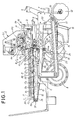
- FIG. 1 is a side elevational view of a seedling transplantation machine on which a seedling transportation apparatus to which the present invention is applied is carried;
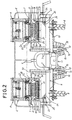
- FIG. 2 is a front elevational view of the seedling transplantation machine of FIG. 1;
- FIG. 3 is a side elevational view showing the seedling transportation apparatus shown in FIG. 1 in a condition wherein the first or leading cell row of a seedling tray stops at a seedling taking out position;
- FIG. 4 is a similar view but showing the seedling transportation apparatus in another condition wherein a trailing cell row of a preceding one of two successive seedling trays placed on a tray transportation apparatus shown in FIG. 1 stops at the seedling taking out position;
- FIG. 5 is a front elevational view of the seedling transportation apparatus shown in FIG. 1;
- FIG. 6 is an enlarged front elevational view showing details of a portion of the seedling transportation apparatus of FIG. 5 around the seedling taking out position;
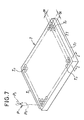
- FIG. 7 is a schematic perspective view of a seedling tray to be used with the seedling transplantation machine of FIG. 1;
- FIG. 8 is a partial enlarged sectional view taken along line I-I of FIG. 7;
- FIG. 9 is a block diagram showing an electric circuit of a driving control section of the seedling transplantation apparatus of FIG. 1;
- FIG. 10 is an enlarged side elevational view of the seedling transportation apparatus of FIG. 5 particularly showing a seedling taking out apparatus and associated elements when the leading cell row of a seedling tray stops at the seedling taking out position;
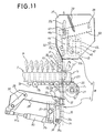
- FIG. 11 is a similar view but showing the seedling taking out apparatus when the second cell row of the seedling tray stops at the seedling taking out position;
- FIG. 12 is an enlarged side elevational view of a transferring apparatus and a seedling holding mechanism of the seedling transportation apparatus of FIG. 5;
- FIG. 13 is a front elevational view of the transferring apparatus and the seedling holding mechanism of FIG. 12; and
- FIG. 14 is a schematic view showing part of a conventional seedling transportation apparatus.
-
- Referring first to FIGS. 1 and 2, there is shown a seedling transplantation machine on which a seedling transportation apparatus to which the present invention is applied is carried.
- The seedling transplantation machine shown includes a
main frame 9 having pairs of upper andlower connection members driving wheels 8 provided on the rear side thereof, and amovable frame 11 mounted for upward and downward pivotal motion around ashaft 10 mounted horizontally at a front portion of themain frame 9. Successively located from the front side to the rear side on themovable frame 11 are a pair ofrolling coulters 12 for cutting disturbing substances, a pair ofopeners 13 for forming furrows, a pair of seedling planting wheels 14 (only one is shown in FIG. 1) for planting seedlings P into the furrows formed by theopeners 13, and two sets of pressing downwheels 15 for pressing down the seedlings P planted by theseedling planting wheels 14. Further, a pair of left and right seedling transportation apparatus A for supplying seedlings P to theseedling planting wheels 14, to which the present invention is applied, are carried on themovable frame 11. - Each of the seedling transportation apparatus A includes a seedling taking out apparatus B for taking out seedlings P upwardly from a seedling tray T, a tray transportation apparatus C for transporting the seedling tray T horizontally toward the seedling taking out apparatus B, and a transferring apparatus E for transferring the seedlings P taken out by the seedling taking out apparatus B to a seedling carrying out conveyor D. The seedling taking out apparatus B, tray transportation apparatus C and transferring apparatus E are carried in an integrated relationship on a
machine frame 16 mounted uprightly at a front portion of themovable frame 11. - Referring to FIGS. 7 and 8, the seedling tray T is generally in the form of a plate made of foamed styrene which cannot be bent during transportation, and has a plurality of seedling accommodating cells (hereinafter referred to simply as cells) Ta formed in a concave condition in a matrix having a pitch α equal in the perpendicular directions on a plane of the seedling tray T. Each of the cells Ta is formed such that the diameter thereof gradually decreases from an upper opening Tb to a bottom portion Td of the cell Ta, and has a rod insertion hole Tc formed in the bottom portion Td thereof.
- Referring back to FIGS. 1 and 2, such seedling trays T are placed horizontally on the tray transportation apparatus C in an upright posture in which leaves Pa of seedlings P accommodated in the cells Ta thereof extend upwardly.
- Referring to FIGS. 1 to 6, the tray transportation apparatus C includes
tray receiving rollers 17a to 17j arranged horizontally for individual rotation at predetermined distances such that two seedling trays T may be placed along upper edges of a pair of left andright base plates 18 between a locationadjacent front ends 18a and another location adjacentrear ends 18b of the left andright base plates 18. - A plurality of
tray moving bars 20 for a moving seedling tray T are mounted horizontally in a predetermined spaced relationship from each other on a pair of left andright roller chains 19. Theroller chains 19 extend along thetray receiving rollers 17a to 17j, and to this end, a pair ofchain stretching shafts tray receiving roller 17a and the rear side with respect to thetray receiving roller 17j, respectively. A furtherchain stretching shaft 24 is mounted between a pair of left andright leg plates 23 of the left andright base plates 18 which extend downwardly below thetray receiving roller 17a as seen in FIGS. 3 to 6. - Pairs of
sprocket wheels 25 for keeping theroller chains 19 taut are secured at the opposite end portions of thechain stretching shafts chain stretching shaft 21 via aroller chain 27 which extends between the motor M1 and asprocket wheel 26 secured to an intermediate portion of thechain stretching shaft 21. - When the motor M1 is energized, the
roller chains 19 are driven to move a seedling tray T toward the seedling taking out apparatus B. Consequently, the seedling tray T is pushed by one of thetray moving bars 20 so that it is moved toward a seedling taking out position R1 at which seedlings P are taken out from the seedling tray T by the seedling taking out apparatus B. - A tray space SP is formed along the upper edges of the left and
right base plates 18 adjacent thefront ends 18a, that is, along a transport path of a seedling tray T below the seedling carrying out conveyor D, so that a seedling tray T may temporarily stay there. Thus, a seedling tray T after it is emptied as seedlings P are taken out therefrom at the seedling taking out position R1 is moved to the tray space SP. - In particular, a seedling tray T moved by one of the
tray moving bars 20 is moved toward the tray space SP while seedlings P are successively taken out therefrom at the seedling taking out position R1 such that, after those seedlings P accommodated in the last cell row Tn of the seedling tray T are taken out from the seedling tray T, the thus emptied seedling tray T stays in the tray space SP (refer to FIGS. 4 and 7). - Driving of the tray transportation apparatus C is controlled by a driving control section F formed from a sequencer or the like. A rotary encoder EN (FIG. 6) connected to an end of the
chain stretching shaft 21, a pair of tray detecting sensors S1 and S1' (FIGS. 5 and 6) provided at upper edge portions of the left andright base plates 18 on the rear side with respect to thechain stretching shaft 21 and a timing signal line TS from the seedling taking out apparatus B are connected to the input side of the driving control section F while the motor M1 is connected to the output side of the driving control section F (FIG. 9). - The driving control section F has the following functions:
- (1) to stop, when a leading end face Tt of a seedling tray T is detected by means of the tray detecting sensors S1 and S1', energization of the motor M1 to stop movement of the seedling tray T to stop the first cell row T1 of the seedling tray T at the seedling taking out position R1 (FIG. 3);
- (2) to calculate the distance of movement of the
seedling tray T based on the angle of rotation of the
chain stretching shaft 21 detected by the rotary encoder EN; and - (3) to discriminate whether or not the calculated distance of movement coincides with the pitch α of the cells Ta formed on the seedling tray T and stop energization of the motor M1 when it coincides with the pitch α. Consequently, the following cell rows are successively stopped at the seedling taking out position R1.
-
- When the leading end face Tt of a seedling tray T placed on the
tray receiving rollers 17a to 17j is detected by the tray detecting sensors S1 and S1', the first cell row T1 of the seedling tray T stops at the seedling taking out position R1. Then, while the first cell row T1 stops there, a taking out operation of seedlings P by the seedling taking out apparatus B is performed. - Then, when an end signal of the taking out operation is outputted from the seedling taking out apparatus B, the driving control section F re-starts energization of the motor M1 to transport the seedling tray T again. Then, when the transport distance of the seedling tray T becomes coincident with the pitch α between the cells Ta formed on the seedling tray T again, the driving control section F stops energization of the motor M1 again so that the next cell row may be stopped at the seedling taking out position R1. The following cell rows are successively stopped at the seedling taking out position R1 in this manner.
- Referring to FIGS. 3, 4, 10 and 11, the seedling taking out apparatus B includes a seedling holding mechanism H which position
seedling holding needles 42, which will be hereinafter described, serving as seedling holding elements in the proximity of the upper openings Tb of those cells Ta stopping at the seedling taking out position R1 for penetrating seedlings P pushed out from the cells Ta, and a seedling pushing out mechanism G for pushing out the seedlings P to be pushed out from the cells Ta until trailing ends Pb of the seedlings P move to the outside of the upper openings Tb. - The seedling pushing out mechanism G includes a pair of pushing up
arms 29 secured at base end portions thereof to ashaft 28 which is supported for rotation on and extends between the left andright base plates 18. Abracket 30 is secured to an intermediate portion of theshaft 28, and a driving rod K1a of a hydraulic or pneumatic fluid pressure cylinder K1 is connected to thebracket 30. The fluid pressure cylinder K1 is mounted by means of abracket 31a on aconnection pipe 31 extending horizontally between the left andright leg plates 23. - Referring to FIGS. 10 and 11, a
rod supporting member 33 having a plurality of seedling pushing outrods 32 formed uprightly thereon extends horizontally between end portions of the pushing uparms 29. Therod supporting member 33 has a pair of downwardly extending vertically elongatedguide elements 35 formed on a lower face thereof, and aguide roller 34 is mounted for rotation at a lower end portion of each of the vertically elongatedguide elements 35. - A
guide plate 36 having a pair of left and rightbent lugs 36a is secured to theconnection pipe 31, and a pair ofarcuate guideways 36b for guiding theguide roller 34 are formed in thebent lugs 36a such that, when theguide roller 34 move along thearcuate guideways 36b, the seedling pushing outrods 32 may be moved upwardly and downwardly substantially in alignment with the seedling taking out position R1. - Referring to FIGS. 5 and 6, each of the seedling pushing out
rods 32 is a round bar member having a thickness with which it can be fitted in the rod insertion hole Tc of a cell Ta of a seedling tray T, and the seedling pushing outrods 32 are disposed in a row in the same pitch α as that of the cells Ta such that they are opposed to the cells Ta which make a row. - If the driving rod K1a of the fluid pressure cylinder K1 is driven to extend, then the pushing up
arms 29 are pivoted around theshaft 28 so that the free end portions thereof may move downwardly. On the other hand, if the driving rod K1a is driven to contract, then the pushing uparms 29 are pivoted around theshaft 28 so that the free end portions thereof may move upwardly. - Consequently, the seedling pushing out
rods 32 are moved back and forth between a pushing out start position R2 at which seedling contacting end faces 32a thereof are spaced downwardly from the rod insertion holes Tc of the opposing cells Ta and a pushing out end position R3 in which the seedling contacting end faces 32a project upwardly through the upper openings Tb of the opposing cells Ta (FIG. 10). - In this manner, seedlings P in those cells Ta stopping at the seedling taking out position R1 are pushed out upwardly from within the cells Ta when the seedling pushing out
rods 32 move to the pushing out end position R3, and then when the seedling pushing outrods 32 further move to the pushing out end position R3, the trailing ends Pb of the seedlings P are moved upwardly away from the upper openings Tb of the cells Ta. - The seedling holding mechanism H is supported by the transferring apparatus E, which will be hereinafter described in detail, such that
seedling holding needles 42 for penetration into seedlings P to be pushed out from those cells Ta stopping at the seedling taking out position R1 may be movable back and forth between a seedling penetrating position R4 at which they are located in the proximity of the upper openings Tb of the cells Ta and a seedling releasing position R5 above the seedling carrying out conveyor D at which they transfer the seedlings P to the seedling carrying out conveyor D. - The seedling holding mechanism H particularly when it moves the
seedling holding needles 42 to the seedling penetrating position R4 will be described below with reference to FIGS. 10 to 13. - A pair of left and
right side plates 37 are supported for upward and downward pivotal motion at lower end portions ofpivotal levers 65 of the transferring apparatus E by means of a pair ofshafts 65a. Ashaft 38 extends horizontally between front portions of the left andright side plates 37, and a pair of needle pulling inlevers 40 are supported at base end portions thereof for pivotal motion on theshaft 38. A pair of tension springs 39 (only one is shown in FIGS. 10 and 11) extend between the needle pulling inlevers 40 and the left and right side plates 37 (FIGS. 10, 11 and 13). - A
guide shaft 41 extends horizontally between end portions of the needle pulling inlevers 40, and aneedle supporting member 43 having a plurality of downwardly extendingseedling holding needles 42 provided thereon is supported for pivotal motion on theguide shaft 41 via abracket 44. A pair of guide rollers 45 (only one is shown in FIGS. 10 and 11) are mounted for rotation at a pair of bent lugs 44a of thebracket 44 viasupport pieces 46. - The seedling holding needles 42 are moved upwardly and downwardly while keeping the downwardly extending postures thereof as the needle pulling in
levers 40 are pivoted upwardly and downwardly around theshaft 38. - The left and
right side plates 37 have arcuate guideways 37a formed therein for guiding theguide shaft 41, and a pair ofguide plates 47 in which arcuate guideways 47a for guiding theguide rollers 45 are formed in inner walls of the left and right side plates 37 (FIGS. 10, 11 and 13). - A pair of
hooks 48 for arresting theguide shaft 41 moved to a position at the lower ends of the arcuate guideways 37a are mounted for rotation on shafts 48a on outer faces of the left andright side plates 37. - Each of the
hooks 48 has a substantially L-shape in side elevation and has a guide shaft arresting portion 48b formed at one of a pair of legs thereof for arresting theguide shaft 41 while aspring mounting piece 48c to which an end of acoil spring 49 having the other end attached to abent lug 37b of a corresponding one of the left andright side plates 37 is to be attached is formed at the other leg of the hook 48 (FIG. 12). Consequently, thehooks 48 are normally biased by the coil springs 49 in a direction in which the guide shaft arresting portions 48b thereof approach theguide shaft 41. - The seedling holding needles 42 have a linear profile and located in pairs at intervals of the pitch α between the cells Ta of a seedling tray T in a row extending along a row of cells. A
seedling releasing plate 50 is provided between lower end portions of the left andright side plates 37 and has formed therein needle looselyfitting holes 50a in which theseedling holding needles 42 are individually fitted loosely (FIGS. 10, 11 and 12). - Located on inner faces of a pair of left and
right support plates 53 of the transferring apparatus E are a pair ofstoppers 51 for moving theguide shaft 41 of the seedling holding mechanism H moved to the seedling penetrating position R4 to the lower ends of the arcuate guideways 37a until theguide shaft 41 is arrested by thehooks 48, and a pair ofarrest releasing members 52 having contacting rollers 52a for contacting with thehooks 48 of the seedling holding mechanism H moved to the seedling releasing position R5 to cancel the arrested condition of theguide shaft 41 by thehooks 48. - In the seedling penetrating position R4, the
guide shaft 41 is arrested by thehooks 48, and consequently, theseedling holding needles 42 are held at pushed down positions in which the lower ends thereof are positioned in the proximity of the upper openings Tb of opposing cells Ta so that seedlings P which are pushed out from the cells Ta may be penetrated by the lower ends of theguide shaft 41 immediately after they start to be pushed out. - Seedlings P in those cells Ta moved to the seedling taking out position R1 are penetrated and held by the
seedling holding needles 42 of the seedling holding mechanism H at the seedling penetrating position R4 immediately after they start to be pushed out by the seedling pushing outrods 32, and as they are thereafter pushed out further by the seedling pushing outrods 32, they are penetrated gradually deeply by the seedling holding needles 42. - Then, when the the seedling pushing out
rods 32 are moved to the pushing out end position R3, that is, when the trailing ends Pb of the seedlings P in the pushing out direction are pushed out to locations above the upper openings Tb of the cells Ta, theseedling holding needles 42 penetrate fully from the leading ends to the trailing ends Pb of the seedlings P in the pushing out direction (FIG. 10). - The transferring apparatus E is constructed in the following manner. In particular, the left and
right support plates 53 are provided uprightly on a pair of mountingframes 54 which are mounted between an upper end portion of themachine frame 16 and intermediate portions of the left andright base plates 18 such that they extend across the tray space SP (FIGS. 1 to 5). - A
connection plate 55 extends horizontally between upper end portions of the left andright support plates 53 and hassupport legs 56 to 58 extending downwardly from a lower face thereof. Asupport shaft 60 extends through and is supported for rotation on thesupport legs 56 to 58, and has a pair ofbrackets 59 secured at the opposite left and right ends thereof. A motor M2 is secured between thesupport legs driving gear 62 is held in meshing engagement with a gear secured to a driving shaft of the motor M2. Thedriving gear 62 is secured to an inner end portion of arotary shaft 63 which is supported for rotation on and extends horizontally between thesupport legs 56 and 57 (FIGS. 12 and 13). - A
lever supporting shaft 64 extends horizontally between front side upper end portions of the left andright support plates 53, and thepivotal levers 65 having the left andright side plates 37 of the seedling holding mechanism H supported for pivotal motion at lower end portions thereof are supported for pivotal motion at upper ends thereof on thelever supporting shaft 64. Further, aconnection member 66 extends horizontally between thepivotal levers 65, and abracket 67 is provided at an intermediate portion of theconnection member 66. Aconnection rod 68 is mounted for rotation at the opposite ends thereof on thebracket 67 and aneccentric mounting pin 62a provided projectingly and eccentrically on thedriving gear 62. - If the
eccentric mounting pin 62a of thedriving gear 62 is rotated forwardly and reversely between a driving start position R6 and a driving end position R7, then thepivotal levers 65 are rocked so that the seedling holding mechanism H may be moved between the seedling penetrating position R4 and the seedling releasing position R5. - A small gear 69 is secured to a central portion of the
support shaft 60 and is held in meshing engagement with thedriving gear 62. A pair of support levers 71 are mounted at upper end portions thereof on thebrackets 59 provided at the opposite left and right end portions of thesupport shaft 60, and the left andright side plates 37 of the seedling holding mechanism H are supported for pivotal motion on ashaft 70 extending horizontally between lower end portions of the support levers 71. - When the
driving gear 62 rotates in the direction indicated by an arrow mark 62' in FIG. 12, theeccentric mounting pin 62a moves from the driving start position R6 toward the driving end position R7, whereupon thebrackets 59 are pivoted upwardly. Thereupon, the left andright side plates 37 of the seedling holding mechanism H are acted upon by a force to pivot them upwardly around theshafts 65a of thepivotal levers 65. Consequently, the seedling holding mechanism H is pivoted upwardly by 90 degrees around theshafts 65a to a posture in which theseedling holding needles 42 extend horizontally, and is moved to the seedling releasing position R5 while keeping the posture. - If the motor M2 rotates reversely, then the seedling holding mechanism H moves back from the seedling releasing position R5 to seedling penetrating position R4 following the locus of movement described above reversely.
- The seedling carrying out conveyor D is supported above the tray space SP formed adjacent the front ends 18a of the left and
right base plates 18, and avertical conveyor 72 for transporting a seedling P toward the correspondingseedling planting wheel 14 is provided adjacent the last end of the seedling carrying out conveyor D in the carrying out direction. - Subsequently, a series of seedling supplying operations by the seedling transportation apparatus A having the construction described above will be described.
- Before a taking out operation for seedlings P is started, the seedling holding mechanism H is moved to the seedling penetrating position R4.
- If seedling trays T are placed on the tray transportation apparatus C and a moving operation of them is started, then the seedling trays T are transported horizontally toward the seedling taking out apparatus B and a preceding one of them is stopped when the first cell row T1 thereof comes to the seedling taking out position R1.
- Then, a pushing out operation for the seedlings P of the first cell row T1 of the seedling tray T is started by the seedling pushing out
rods 32 of the seedling pushing out mechanism G so that the seedlings P are individually penetrated by the correspondingseedling holding needles 42 until they are held by the seedling holding needles 42. - After completion of the penetration operation into the seedlings P, the seedling pushing out
rods 32 are moved back to the pushing out start position R2, and the seedling holding mechanism H is moved from the seedling penetrating position R4 toward the seedling releasing position R5 while it is pivoted upwardly by 90 degrees around theshafts 65a. - When the seedling holding mechanism H comes to the seedling releasing position R5, the
hooks 48 are brought into contact with the contacting rollers 52a of thearrest releasing members 52 to cancel the arrested condition of theguide shaft 41 by thehooks 48, and consequently, theseedling holding needles 42 are pulled in rapidly between the left andright side plates 37. - By the pulling in operation, the seedlings P which have been penetrated by the
seedling holding needles 42 are pulled out and released by theseedling releasing plate 50 and placed onto the seedling carrying out conveyor D therebelow. The seedlings P placed on the seedling carrying out conveyor D are thereafter transferred to thevertical conveyor 72 and transported toward theseedling planting wheel 14 by thevertical conveyor 72. - When the seedlings P are released, the seedling holding mechanism H is moved back toward the seedling penetrating position R4, and the seedling pushing out
rods 32 of the seedling pushing out mechanism G are moved back to the pushing out start position R2. Then, also the tray transportation apparatus C is driven to move the seedling tray T so that the next cell row may come to the seedling taking out position R1. Consequently, the seedling tray T is moved gradually into the tray space SP by the driving of the tray transportation apparatus C. - After taking out of the seedlings P accommodated in the seedling tray T is completed in this manner, the entire seedling tray T is moved to the tray space SP, in which it thereafter stays for a certain period of time.
- Then, when seedlings P accommodated in a following seedling tray T are started to be taken out from the seedling tray T in a similar manner to that from the preceding seedling tray T, the leading end of the following seedling tray T is brought into contact with and urges the rear end of the preceding seedling tray T to move the preceding seedling tray T.
- It is to be noted that the present invention is not limited to the specific embodiment described above, but can be embodied in various forms within the spirit and scope of the invention.
- For example, while, in the embodiment described above, the tray space is constructed such that a single seedling tray T may temporarily stay therein, it may be constructed otherwise such that a seedling tray moved later may be placed on another seedling tray moved earlier so that several seedling trays may temporarily stay in a piled up condition in the tray space. With the alternative construction, the time until seedling trays staying in the tray space must be removed can be set comparatively long, and the seedling tray exchanging operation can be further moderated.
- Or, the tray space for allowing a seedling tray to temporarily stay therein need not be formed, but upon transferring operation of seedlings to the seedling carrying out conveyor, a seedling tray may be moved successively to a location below the seedling carrying out conveyor.
- Having now fully described the invention, it will be apparent to one of ordinary skill in the art that many changes and modifications can be made thereto without departing from the spirit and scope of the invention as set forth herein.
Claims (3)
- A seedling transportation apparatus for a transplantation machine, comprising:a seedling taking out apparatus (B) for taking out a seedling (P) upwardly from a seedling tray (T) having seedling accommodating cells (Ta) in which seedlings (P) are accommodated;a tray transportation apparatus (C) having a horizontal transport path for transporting the seedling tray (T) toward said seedling taking out apparatus (B);a seedling carrying out conveyor (D); anda transferring apparatus (E) for transferring the seedling (P) taken out by said seedling taking out apparatus (B) onto said seedling carrying out conveyor (D), characterized in that said seedling carrying out conveyor (D) is disposed at a location higher than said horizontal transport path of said tray transportation apparatus (C) for defining a tray space (SP) formed on the downstream side of said tray transportation apparatus (C) below said seedling carrying out conveyor (D).
- A seedling transportation apparatus for a transplantation machine as set forth in claim 1, characterized in that said seedling taking out apparatus (B) includes a seedling pushing out mechanism (G) for pushing out a seedling (P ) upwardly from the seedling tray (T) and a seedling holding mechanism (H) for holding the seedling (P) pushed out by said seedling pushing out mechanism (G).
- A seedling transportation apparatus for a transplantation machine as set forth in claim 2, characterized in that said transferring apparatus (E) moves said seedling holding mechanism (H) back and forth between a seedling penetrating position (R4) at which said seedling holding mechanism (H) receives a seedling (P) in a cell (Ta) of the seedling tray (T) and a seedling releasing position (R5) at which said seedling holding mechanism (H) releases the received seedling (P) toward said seedling carrying out conveyor (D).
Applications Claiming Priority (3)
| Application Number | Priority Date | Filing Date | Title |
|---|---|---|---|
| JP13978396A JP3215941B2 (en) | 1996-05-10 | 1996-05-10 | Seedling transfer device and its transfer method |
| JP13978396 | 1996-05-10 | ||
| JP139783/96 | 1996-05-10 |
Publications (2)
| Publication Number | Publication Date |
|---|---|
| EP0806131A1 EP0806131A1 (en) | 1997-11-12 |
| EP0806131B1 true EP0806131B1 (en) | 2001-10-10 |
Family
ID=15253326
Family Applications (1)
| Application Number | Title | Priority Date | Filing Date |
|---|---|---|---|
| EP97104432A Expired - Lifetime EP0806131B1 (en) | 1996-05-10 | 1997-03-14 | Seedling transportation apparatus for transplantation Machine |
Country Status (8)
| Country | Link |
|---|---|
| US (1) | US5784984A (en) |
| EP (1) | EP0806131B1 (en) |
| JP (1) | JP3215941B2 (en) |
| AT (1) | ATE206580T1 (en) |
| DE (1) | DE69707193T2 (en) |
| DK (1) | DK0806131T3 (en) |
| ES (1) | ES2165539T3 (en) |
| PT (1) | PT806131E (en) |
Families Citing this family (12)
| Publication number | Priority date | Publication date | Assignee | Title |
|---|---|---|---|---|
| JP3849084B2 (en) * | 1997-09-08 | 2006-11-22 | 株式会社サークル鉄工 | Method and apparatus for removing seedling from seedling tray |
| US20060130720A1 (en) | 2003-05-01 | 2006-06-22 | Bart Parrein | Method and apparatus for transporting seedlings in a planting machine |
| CN103125300B (en) * | 2013-03-12 | 2014-04-02 | 阳曲县诚同茂业科技有限公司 | Combined driving cross seedling set |
| FI125975B (en) | 2014-10-31 | 2016-05-13 | Risutec Oy | Method of seedling planter and seedling planter |
| USD783421S1 (en) | 2016-01-05 | 2017-04-11 | Van Belle Nursery Inc. | Seedling tray |
| DK179090B1 (en) * | 2016-06-17 | 2017-10-23 | Ellepot As | Apparatus and system for transporting a length of growth medium cut into pieces of suitable size into a propagation tray |
| EP3547816B1 (en) * | 2016-11-29 | 2023-07-19 | Tigercat Industries Inc. | Apparatus for planting tree seedlings |
| CN107624314B (en) * | 2017-11-15 | 2023-10-20 | 河南科技大学 | Seedling tray automatic conveying device for seedling transplanting machine |
| CN109348796B (en) * | 2018-11-05 | 2021-12-07 | 华中农业大学 | Rape matrix block seedling transplanting device |
| CN109601080A (en) * | 2019-01-21 | 2019-04-12 | 东北农业大学 | A kind of seedling-transplanting device |
| CN110149969B (en) * | 2019-06-25 | 2021-07-30 | 合肥流荇蓝色农业有限公司 | Seedling feeding matching device for movable seedbed and using method of seedling feeding matching device |
| CN115104412A (en) * | 2020-11-07 | 2022-09-27 | 孙景旺 | Using method of transplanting device for agricultural machinery |
Family Cites Families (14)
| Publication number | Priority date | Publication date | Assignee | Title |
|---|---|---|---|---|
| FI69542C (en) * | 1979-02-02 | 1986-03-10 | Serlachius Oy | FOERFARANDE OCH APPARAT FOER MATNING AV PLANTCELLER I EN PLANTERINGSMASKIN |
| US4440101A (en) * | 1979-12-18 | 1984-04-03 | Illinois Tool Works Inc. | Plant transfer mechanism |
| CA1137826A (en) * | 1979-12-18 | 1982-12-21 | Bryant Edwards | Plant transfer mechanism |
| GB8426656D0 (en) * | 1984-10-22 | 1984-11-28 | Chamberlain R A | Transplanter |
| US4644880A (en) * | 1985-02-22 | 1987-02-24 | Growers Transplanting, Inc. | Method and apparatus for transplanting corps |
| EP0396208A3 (en) * | 1986-04-23 | 1991-01-09 | Ateliers De Claire Fontaine | Transplanter for potballplants |
| US4750439A (en) * | 1986-08-27 | 1988-06-14 | Bud Antle, Inc. | Planting finger assembly |
| FI84870C (en) * | 1987-11-02 | 1992-02-10 | Laennen Tehtaat Oy | FOERFARANDE OCH ANORDNING FOER PLANTERING AV KLUMPPLANTOR. |
| GB9119423D0 (en) * | 1991-09-11 | 1991-10-23 | Chamberlain Richard A | Seedling transplanter |
| US5320649A (en) * | 1992-08-18 | 1994-06-14 | Holland James J | Plant transplant system |
| EP0613614B1 (en) * | 1993-03-04 | 1999-09-08 | YANMAR AGRICULTURAL EQUIPMENT Co., Ltd. | Seedling planting apparatus |
| JPH07184419A (en) * | 1993-12-28 | 1995-07-25 | Yanmar Agricult Equip Co Ltd | Method for taking seedling stock of vegetable transplantation machine |
| JPH07184421A (en) * | 1993-12-28 | 1995-07-25 | Yanmar Agricult Equip Co Ltd | Longitudinal tray feeder of transplanter |
| US5557881A (en) * | 1995-02-21 | 1996-09-24 | Bouldin; Floyd | Seedling transplanter |
-
1996
- 1996-05-10 JP JP13978396A patent/JP3215941B2/en not_active Expired - Fee Related
-
1997
- 1997-03-14 DK DK97104432T patent/DK0806131T3/en active
- 1997-03-14 ES ES97104432T patent/ES2165539T3/en not_active Expired - Lifetime
- 1997-03-14 EP EP97104432A patent/EP0806131B1/en not_active Expired - Lifetime
- 1997-03-14 DE DE69707193T patent/DE69707193T2/en not_active Expired - Fee Related
- 1997-03-14 PT PT97104432T patent/PT806131E/en unknown
- 1997-03-14 US US08/818,546 patent/US5784984A/en not_active Expired - Lifetime
- 1997-03-14 AT AT97104432T patent/ATE206580T1/en not_active IP Right Cessation
Also Published As
| Publication number | Publication date |
|---|---|
| ES2165539T3 (en) | 2002-03-16 |
| US5784984A (en) | 1998-07-28 |
| DE69707193T2 (en) | 2002-03-14 |
| ATE206580T1 (en) | 2001-10-15 |
| JP3215941B2 (en) | 2001-10-09 |
| DE69707193D1 (en) | 2001-11-15 |
| JPH09298917A (en) | 1997-11-25 |
| DK0806131T3 (en) | 2001-11-19 |
| EP0806131A1 (en) | 1997-11-12 |
| PT806131E (en) | 2002-01-30 |
Similar Documents
| Publication | Publication Date | Title |
|---|---|---|
| EP0806131B1 (en) | Seedling transportation apparatus for transplantation Machine | |
| US6044778A (en) | Method and device for picking up seedlings from seedling tray | |
| JPH04367417A (en) | Method and device for automatic aligned feeding of article to packaging machine | |
| US5983812A (en) | Seedling with soil selecting and transporting apparatus for transplanting machine | |
| EP1306307A1 (en) | Cover feeder | |
| JPH09154328A (en) | Seedling tray-pressing device for transplanter | |
| JP2860251B2 (en) | Means for preventing leaf pinching in seedling supply device for transplanter | |
| JP3750837B2 (en) | Nursery container stacking equipment | |
| JPH09266707A (en) | Conveying of seedling stock tray and apparatus therefor | |
| JP3365740B2 (en) | Transplanter seedling tray feeder | |
| JP3384056B2 (en) | Seedling supply device | |
| JP3147047B2 (en) | Seedling machine | |
| JP2555229B2 (en) | Transplanter seedling feeder | |
| JP2803977B2 (en) | Tray seedling correction mechanism of transplanter | |
| JP2853021B2 (en) | Method and apparatus for transferring rows of linked seedlings | |
| JP2000116216A (en) | Seedling transplanter | |
| JPH0647209Y2 (en) | Planting machine seedling stand | |
| JP3369311B2 (en) | Transplant machine | |
| JPS61231912A (en) | Seedling feed controller of transplanter | |
| JPH04237416A (en) | Seedling-feeding device for rice transplanter | |
| JP2547678Y2 (en) | Transplanter seedling loading device | |
| JPH11199051A (en) | Rising seedling vessel step tiering device | |
| JPH0775409A (en) | Sensor for defective seedling of rice transplanter | |
| JP2000270688A (en) | Device for charging seedling-raising mat | |
| JPH04104709A (en) | Apparatus for automatic feeding of seedling to transplantation machine |
Legal Events
| Date | Code | Title | Description |
|---|---|---|---|
| PUAI | Public reference made under article 153(3) epc to a published international application that has entered the european phase |
Free format text: ORIGINAL CODE: 0009012 |
|
| AK | Designated contracting states |
Kind code of ref document: A1 Designated state(s): AT BE CH DE DK ES FI FR GB GR IE IT LI LU MC NL PT SE |
|
| 17P | Request for examination filed |
Effective date: 19980511 |
|
| 17Q | First examination report despatched |
Effective date: 20000214 |
|
| GRAG | Despatch of communication of intention to grant |
Free format text: ORIGINAL CODE: EPIDOS AGRA |
|
| GRAG | Despatch of communication of intention to grant |
Free format text: ORIGINAL CODE: EPIDOS AGRA |
|
| GRAH | Despatch of communication of intention to grant a patent |
Free format text: ORIGINAL CODE: EPIDOS IGRA |
|
| GRAH | Despatch of communication of intention to grant a patent |
Free format text: ORIGINAL CODE: EPIDOS IGRA |
|
| GRAA | (expected) grant |
Free format text: ORIGINAL CODE: 0009210 |
|
| AK | Designated contracting states |
Kind code of ref document: B1 Designated state(s): AT BE CH DE DK ES FI FR GB GR IE IT LI LU MC NL PT SE |
|
| REF | Corresponds to: |
Ref document number: 206580 Country of ref document: AT Date of ref document: 20011015 Kind code of ref document: T |
|
| REG | Reference to a national code |
Ref country code: CH Ref legal event code: NV Representative=s name: PA ALDO ROEMPLER Ref country code: CH Ref legal event code: EP |
|
| REG | Reference to a national code |
Ref country code: IE Ref legal event code: FG4D |
|
| REF | Corresponds to: |
Ref document number: 69707193 Country of ref document: DE Date of ref document: 20011115 |
|
| REG | Reference to a national code |
Ref country code: DK Ref legal event code: T3 |
|
| ET | Fr: translation filed | ||
| REG | Reference to a national code |
Ref country code: GB Ref legal event code: IF02 |
|
| REG | Reference to a national code |
Ref country code: PT Ref legal event code: SC4A Free format text: AVAILABILITY OF NATIONAL TRANSLATION Effective date: 20011031 |
|
| REG | Reference to a national code |
Ref country code: ES Ref legal event code: FG2A Ref document number: 2165539 Country of ref document: ES Kind code of ref document: T3 |
|
| REG | Reference to a national code |
Ref country code: GR Ref legal event code: EP Ref document number: 20010402636 Country of ref document: GR |
|
| PLBE | No opposition filed within time limit |
Free format text: ORIGINAL CODE: 0009261 |
|
| STAA | Information on the status of an ep patent application or granted ep patent |
Free format text: STATUS: NO OPPOSITION FILED WITHIN TIME LIMIT |
|
| 26N | No opposition filed | ||
| PGFP | Annual fee paid to national office [announced via postgrant information from national office to epo] |
Ref country code: MC Payment date: 20060322 Year of fee payment: 10 Ref country code: FI Payment date: 20060322 Year of fee payment: 10 |
|
| PGFP | Annual fee paid to national office [announced via postgrant information from national office to epo] |
Ref country code: GR Payment date: 20060323 Year of fee payment: 10 |
|
| PGFP | Annual fee paid to national office [announced via postgrant information from national office to epo] |
Ref country code: CH Payment date: 20060324 Year of fee payment: 10 |
|
| PGFP | Annual fee paid to national office [announced via postgrant information from national office to epo] |
Ref country code: DK Payment date: 20060328 Year of fee payment: 10 |
|
| PGFP | Annual fee paid to national office [announced via postgrant information from national office to epo] |
Ref country code: LU Payment date: 20060329 Year of fee payment: 10 |
|
| PG25 | Lapsed in a contracting state [announced via postgrant information from national office to epo] |
Ref country code: FI Free format text: LAPSE BECAUSE OF NON-PAYMENT OF DUE FEES Effective date: 20070314 |
|
| PG25 | Lapsed in a contracting state [announced via postgrant information from national office to epo] |
Ref country code: SE Free format text: LAPSE BECAUSE OF NON-PAYMENT OF DUE FEES Effective date: 20070315 |
|
| REG | Reference to a national code |
Ref country code: DK Ref legal event code: EBP |
|
| REG | Reference to a national code |
Ref country code: CH Ref legal event code: PL |
|
| EUG | Se: european patent has lapsed | ||
| PG25 | Lapsed in a contracting state [announced via postgrant information from national office to epo] |
Ref country code: MC Free format text: LAPSE BECAUSE OF NON-PAYMENT OF DUE FEES Effective date: 20070331 |
|
| PGFP | Annual fee paid to national office [announced via postgrant information from national office to epo] |
Ref country code: SE Payment date: 20060324 Year of fee payment: 10 |
|
| PG25 | Lapsed in a contracting state [announced via postgrant information from national office to epo] |
Ref country code: CH Free format text: LAPSE BECAUSE OF NON-PAYMENT OF DUE FEES Effective date: 20070331 Ref country code: LI Free format text: LAPSE BECAUSE OF NON-PAYMENT OF DUE FEES Effective date: 20070331 |
|
| PG25 | Lapsed in a contracting state [announced via postgrant information from national office to epo] |
Ref country code: DK Free format text: LAPSE BECAUSE OF NON-PAYMENT OF DUE FEES Effective date: 20070402 |
|
| PGFP | Annual fee paid to national office [announced via postgrant information from national office to epo] |
Ref country code: ES Payment date: 20080326 Year of fee payment: 12 |
|
| PGFP | Annual fee paid to national office [announced via postgrant information from national office to epo] |
Ref country code: PT Payment date: 20080305 Year of fee payment: 12 Ref country code: IE Payment date: 20080320 Year of fee payment: 12 Ref country code: GB Payment date: 20080318 Year of fee payment: 12 |
|
| PGFP | Annual fee paid to national office [announced via postgrant information from national office to epo] |
Ref country code: AT Payment date: 20080319 Year of fee payment: 12 |
|
| PGFP | Annual fee paid to national office [announced via postgrant information from national office to epo] |
Ref country code: FR Payment date: 20080314 Year of fee payment: 12 Ref country code: DE Payment date: 20080327 Year of fee payment: 12 |
|
| PGFP | Annual fee paid to national office [announced via postgrant information from national office to epo] |
Ref country code: BE Payment date: 20080321 Year of fee payment: 12 |
|
| PGFP | Annual fee paid to national office [announced via postgrant information from national office to epo] |
Ref country code: IT Payment date: 20080329 Year of fee payment: 12 |
|
| PG25 | Lapsed in a contracting state [announced via postgrant information from national office to epo] |
Ref country code: GR Free format text: LAPSE BECAUSE OF NON-PAYMENT OF DUE FEES Effective date: 20071003 |
|
| PGFP | Annual fee paid to national office [announced via postgrant information from national office to epo] |
Ref country code: NL Payment date: 20080318 Year of fee payment: 12 |
|
| PG25 | Lapsed in a contracting state [announced via postgrant information from national office to epo] |
Ref country code: LU Free format text: LAPSE BECAUSE OF NON-PAYMENT OF DUE FEES Effective date: 20070314 |
|
| REG | Reference to a national code |
Ref country code: PT Ref legal event code: MM4A Free format text: LAPSE DUE TO NON-PAYMENT OF FEES Effective date: 20090914 |
|
| BERE | Be: lapsed |
Owner name: *CIRCLE TEKKO CO. LTD Effective date: 20090331 |
|
| PG25 | Lapsed in a contracting state [announced via postgrant information from national office to epo] |
Ref country code: PT Free format text: LAPSE BECAUSE OF NON-PAYMENT OF DUE FEES Effective date: 20090914 Ref country code: AT Free format text: LAPSE BECAUSE OF NON-PAYMENT OF DUE FEES Effective date: 20090314 |
|
| GBPC | Gb: european patent ceased through non-payment of renewal fee |
Effective date: 20090314 |
|
| NLV4 | Nl: lapsed or anulled due to non-payment of the annual fee |
Effective date: 20091001 |
|
| REG | Reference to a national code |
Ref country code: FR Ref legal event code: ST Effective date: 20091130 |
|
| REG | Reference to a national code |
Ref country code: IE Ref legal event code: MM4A |
|
| PG25 | Lapsed in a contracting state [announced via postgrant information from national office to epo] |
Ref country code: IE Free format text: LAPSE BECAUSE OF NON-PAYMENT OF DUE FEES Effective date: 20090316 Ref country code: DE Free format text: LAPSE BECAUSE OF NON-PAYMENT OF DUE FEES Effective date: 20091001 |
|
| PG25 | Lapsed in a contracting state [announced via postgrant information from national office to epo] |
Ref country code: BE Free format text: LAPSE BECAUSE OF NON-PAYMENT OF DUE FEES Effective date: 20090331 Ref country code: NL Free format text: LAPSE BECAUSE OF NON-PAYMENT OF DUE FEES Effective date: 20091001 |
|
| PG25 | Lapsed in a contracting state [announced via postgrant information from national office to epo] |
Ref country code: GB Free format text: LAPSE BECAUSE OF NON-PAYMENT OF DUE FEES Effective date: 20090314 Ref country code: FR Free format text: LAPSE BECAUSE OF NON-PAYMENT OF DUE FEES Effective date: 20091123 |
|
| REG | Reference to a national code |
Ref country code: ES Ref legal event code: FD2A Effective date: 20090316 |
|
| PG25 | Lapsed in a contracting state [announced via postgrant information from national office to epo] |
Ref country code: ES Free format text: LAPSE BECAUSE OF NON-PAYMENT OF DUE FEES Effective date: 20090316 |
|
| PG25 | Lapsed in a contracting state [announced via postgrant information from national office to epo] |
Ref country code: IT Free format text: LAPSE BECAUSE OF NON-PAYMENT OF DUE FEES Effective date: 20090314 |