EP0806052B1 - Plasma reactor - Google Patents
Plasma reactor Download PDFInfo
- Publication number
- EP0806052B1 EP0806052B1 EP95940955A EP95940955A EP0806052B1 EP 0806052 B1 EP0806052 B1 EP 0806052B1 EP 95940955 A EP95940955 A EP 95940955A EP 95940955 A EP95940955 A EP 95940955A EP 0806052 B1 EP0806052 B1 EP 0806052B1
- Authority
- EP
- European Patent Office
- Prior art keywords
- plasma reactor
- cavity resonator
- reactor according
- region
- field strength
- Prior art date
- Legal status (The legal status is an assumption and is not a legal conclusion. Google has not performed a legal analysis and makes no representation as to the accuracy of the status listed.)
- Expired - Lifetime
Links
Images


Classifications
-
- H—ELECTRICITY
- H01—ELECTRIC ELEMENTS
- H01J—ELECTRIC DISCHARGE TUBES OR DISCHARGE LAMPS
- H01J37/00—Discharge tubes with provision for introducing objects or material to be exposed to the discharge, e.g. for the purpose of examination or processing thereof
- H01J37/32—Gas-filled discharge tubes
- H01J37/32009—Arrangements for generation of plasma specially adapted for examination or treatment of objects, e.g. plasma sources
- H01J37/32192—Microwave generated discharge
- H01J37/32211—Means for coupling power to the plasma
- H01J37/32229—Waveguides
-
- H—ELECTRICITY
- H01—ELECTRIC ELEMENTS
- H01J—ELECTRIC DISCHARGE TUBES OR DISCHARGE LAMPS
- H01J37/00—Discharge tubes with provision for introducing objects or material to be exposed to the discharge, e.g. for the purpose of examination or processing thereof
- H01J37/32—Gas-filled discharge tubes
- H01J37/32009—Arrangements for generation of plasma specially adapted for examination or treatment of objects, e.g. plasma sources
- H01J37/32192—Microwave generated discharge
- H01J37/32211—Means for coupling power to the plasma
- H01J37/32247—Resonators
Definitions
- the invention relates to a plasma reactor for Generating and maintaining a plasma, in particular for the deposition of diamond, with a frequency generator and with one from the frequency generator via at least one coupling element with electromagnetic Waves fed cavity resonator, where in the cavity resonated by a wall a reaction unit in an area of high field strength can be introduced.
- Such a plasma reactor is known from WO 88/10506 or the publication "Diamond deposition technologies" by PK Bachmann and W. van Enckevort, published in the magazine Diamond and Related Materials, Volume 1, pages 1021 to 1034 in 1992.
- microwaves generated by means of a frequency generator can be coupled via a pin coupler into a cavity resonator equipped with an expanding waveguide section on the coupling side in WO 88/10506 to enlarge the field, said cavity resonator being formed as a cylinder resonator by a cylindrical tube closed at the end.
- a reaction unit with a substrate to be coated from a gas phase formed by an ignited plasma is arranged at the closed end of the cylinder resonator opposite the pin coupler.
- an optical furnace is included a plasma lamp known as a light source, the over has an ellipsoidal reflector.
- the plasma lamp is in a focal point of the ellipsoid reflector arranged while one sample in the other Focus is positioned.
- the invention has for its object a To create plasma reactor that is at one another largely independent choice of process parameters such as gas pressure and injected electromagnetic power through a spatially stable, over the deposit area of a Characterized substrates homogeneously distributed plasma.
- this object is achieved by that the cavity resonator with a through cross-sectional constrictions tapering in apex areas Wall is formed, the cavity resonator tapered as far as possible in the crown areas is that the one defined by the wall Field strength distribution at least two main maxima has, whose maximum field strength compared to Field strengths of neighboring secondary maxima are excessive, that about the or each coupling element, the electromagnetic Waves arranged in the area Main maximums can be fed into the cavity resonator are and that the reaction unit in the range of further main maximum is arranged.
- ellipsoidal tapering design of the cavity resonator is a field fashion as an overlay of eigenmodes with at least two main maxima generated in their field strength significantly above that Field strengths of neighboring secondary maxima are excessive.
- the spatial distribution of this field fashion is from the electromagnetic coupled into the cavity power a burning plasma and especially from slight deformations in the wall of the cavity resonator largely independent.
- reaction unit in the area of one of the main maxima is now a spatially stable and with variation of process parameters such as gas pressure and / or coupled electromagnetic power in its location largely uninfluenced as well as proportionately large area homogeneously burning plasma can be generated with the hard material in thin-film technology layers, especially diamond layers, in the Material Synthesis Plasma Polymerization and Powder Synthesis Processes and in plasma surface treatment Nitriding and etching treatments can be carried out.
- the cavity resonator as an ellipsoid, as a ring-shaped, conical one Wall segments molded in sections, segmented Ellipsoid or as one in the area of a main maximum in the Diameter-widened asymmetrical ellipsoid educated.
- the tapered areas as rotationally symmetrical Paraboloid sections provided over a cylinder section are put together.
- the cavity resonator by two joined together in the direction of the longitudinal axes Ellipsoidal sections formed, the Reaction unit in the area of the joint of the ellipsoid sections a developing, very intense Including central maximum is arranged.
- this Double ellipsoid resonator is the electromagnetic one Power at the opposite of the reaction unit Vertex sections of the ellipsoid sections can be coupled in.
- a microwave transmitter 1 as a frequency generator, with which an electromagnetic wave in a transverse electrical (TE) fashion into one Output waveguide 2 can be coupled.
- the frequency of the electromagnetic wave is in the microwave range and is for example 2.45 gigahertz. In a The frequency is approximately 915 megahertz.
- the electromagnetic guided in the output waveguide 2 Shaft is fed to a circulator 3, with the feedback of reflected parts in the Microwave transmitter 1 can be suppressed.
- an impedance converter 4 which is in a coupling waveguide 5 insertable alignment pins 6, 7, 8 equipped is.
- the coupling waveguide 5 is a rectangular waveguide, the with a short-circuit slide 9 in Direction of propagation of the electromagnetic wave is completed.
- the stamp of the short circuit slide 9 is displaceable in the longitudinal direction of the coupling waveguide 5.
- the coupling waveguide 5 has a section in FIG a cylindrical coupling piece 10 on one side wall on that in a trained as an ellipsoid resonator 11 Cavity protrudes.
- the ellipsoid resonator 11 encloses the volume of an elongated Ellipsoids with two short semiaxes of equal length and is made of an electrically conductive material like one adapted for waveguide production Made of aluminum alloy or brass alloy.
- the coupling waveguide is centered in the coupling piece 10 5 crossing coupling pin 12 arranged, which runs in the longitudinal axis of the ellipsoid resonator 11.
- the coupling pin 12 is for tuning in the longitudinal direction slidable.
- the stamp of the short circuit slide 9 is in a position in the area of the coupling pin 12 is an antinode of the electromagnetic Wave is present.
- Vertex area 16 of the ellipsoid resonator 11 is on an end plate 17 of a reaction unit 18th appropriate.
- a quartz bell 19 attached as a conclusion that in the interior of the Ellipsoidresonators 11 protrudes and together with the End plate 17 encloses a reaction volume 20.
- Within the reaction volume 20 is on the end plate 17 applied a substrate 21, which by means of a fluid passing through cooling lines 22, 23, 24 can be cooled from a fluid bath 25.
- a reaction gas which can be metered with a first throttle valve 28 and which is a carbon-containing gas such as CH 4 or CO for depositing diamond, for example, can be introduced into the reaction volume 20 via a gas inlet line 27 connected to a storage container 26. Furthermore, the reaction volume 20 can be evacuated by means of a vacuum pump 30 connected to the reaction volume 20 via a gas outlet line 29, the pumping rate being achieved by means of a second throttle valve 28 'provided in the gas outlet line 29. is adjustable.
- the plasma reactor When the plasma reactor is operating, it builds up in the cavity one formed from superimposed eigenmodes Field mode as field strength distribution, which in the case of Ellipsoid resonator 11 two areas of excessive field strength has which essentially around the coupling-in side Main maximum 15 and around yourself within of the reaction volume 20 located on the reaction side Main maximum 31 lie.
- a coupled microwave power typically a few kilowatts as well Gas pressures of several ten millibars ignite in the area that is within the reaction volume 20 Main maximum 31 is a plasma 32, which the substrate 21st surrounds.
- a low frequency of electromagnetic Waves for example the aforementioned 915 Megahertz, is over the surface of the substrate 21, due to the stable position of the reaction side Main maximum 31, a large-area homogeneous plasma generated.
- the field mode when changing the coupled electromagnetic Performance is still the process parameter Gas pressure and microwave power over a wide range Range adjustable independently of each other without it to ignite a plasma discharge in the area of Secondary maxima 38, 39, 40, 41 comes.
- the plasma remains at the position of the Plasma maximums 37 even when the coupled ones are varied electromagnetic power stably positioned without that there is a fashion jumping.
- the Position of the plasma 32 also in relation to geometrical ones Modifications such as those introduced when different configured reaction units 18 occur, relatively insensitive.
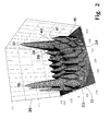
- Fig. 3 shows the electric field strength of the field mode of the Ellipsoid resonator 11 according to FIG. 2 in a two-dimensional Contour display.
- Areas 42 without Hatching indicate a field strength in arbitrary units from 0 to 299, in the illustration according to FIG. 3 areas shaded from right to left 43 have a field strength of 300 to 499, from left to right Hatched areas 44 on the right have a Field strength from 500 to 699, cross-hatched areas 45 have a field strength of 700 to 899 and that black filled tip of the first main maximum range 36 and the blackened tip of the second main maximum region 37 have a field strength from 900 to 1000.
- Fig. 4 shows a partially sectioned view Part of a plasma reactor according to FIG. 1 with an as ellipsoidal segment resonator 46 designed cavity resonator, which is concentric around the longitudinal axis arranged annular wall segments 47 built is.
- the wall segments 47 are in the direction of the apex regions 13, 16 tapered, joined together Tapered shell section surfaces, approximately one Enclose ellipsoidal cavity.
- the segment resonator 46 is especially at low frequencies relative to one-piece cavity resonators easy to manufacture as it is made out of simple to be manufactured wall segments 47 can be assembled.
- the Elevation of the main maxima 15, 31 compared to the secondary maxima is only insignificant due to the segmentation influenced.
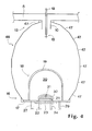
- Fig. 5 shows a part in a partial sectional view of a plasma reactor according to FIG. 1 with an asymmetrical Bell resonator 48, the wall 49 in the tapering in the direction of the end plate 17
- the apex region 16 is dashed compared to that in FIG. 5 shown wall 14 of a symmetrical ellipsoid resonator is expanded.
- the surface of the substrate 21 leads to uniform Deposition conditions from the plasma 32.
- Fig. 6 shows a section of a plasma reactor according to Fig. 1 in a partial sectional view with a paraboloid resonator 51, whose apex regions 13, 16 through Paraboloid sections 52, 52 'are formed.
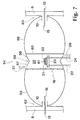
- Fig. 7 shows a in a partially sectioned view 1 with a double ellipsoid resonator 54, which consists of two separated walls 55, 56 is formed by ellipsoidal sections.
- the joined together, tapered apex areas 57, 58 the walls 55, 56 form a constriction 59, the symmetrically that enclosed by a quartz tube 60 End of reaction volume 20 limited.
- the constriction 59 is one of two superimposed main maxima of the tapering vertex areas 57, 58 of the ellipsoidal sections formed Central maximum 61, in the vicinity of which the plasma 32 ignites and the substrate 21 is coatable.
Landscapes
- Physics & Mathematics (AREA)
- Engineering & Computer Science (AREA)
- Plasma & Fusion (AREA)
- Chemical & Material Sciences (AREA)
- Analytical Chemistry (AREA)
- Physical Or Chemical Processes And Apparatus (AREA)
- Plasma Technology (AREA)
Description
Die Erfindung betrifft einen Plasmareaktor zum Erzeugen und Unterhalten eines Plasmas, insbesondere zum Abscheiden von Diamant, mit einem Frequenzgenerator und mit einem von dem Frequenzgenerator über wenigstens ein Koppelelement mit elektromagnetischen Wellen gespeisten Hohlraumresonator, wobei in den von einer Wandung begrenzten Hohlraumresonator in einem Bereich hoher Feldstärke eine Reaktionseinheit einbringbar ist.The invention relates to a plasma reactor for Generating and maintaining a plasma, in particular for the deposition of diamond, with a frequency generator and with one from the frequency generator via at least one coupling element with electromagnetic Waves fed cavity resonator, where in the cavity resonated by a wall a reaction unit in an area of high field strength can be introduced.
Ein derartiger Plasmareaktor ist aus der WO
88/10506 oder auch der Publikation "Diamond deposition
technologies" von P.K. Bachmann und W. van
Enckevort, erschienen in der Zeitschrift Diamond
and Related Materials, Band 1, Seiten 1021 bis 1034
im Jahr 1992, bekannt. Bei diesem Plasmareaktor
sind mittels eines Frequenzgenerators erzeugte
Mikrowellen über einen Stiftkoppler in einen bei
der WO 88/10506 zum Vergrößern des Feldes einkoppelseitig
mit einem sich erweiternden Wellenleitabschnitt
ausgestatteten Hohlraumresonator einkoppelbar,
der durch ein endseitig geschlossenes zylindrisches
Rohr als Zylinderresonator ausgebildet
ist. An dem dem Stiftkoppler gegenüberliegenden geschlossenen
Ende des Zylinderresonators ist eine
Reaktionseinheit mit einem aus einer durch ein
gezündetes Plasma gebildeten Gasphase zu beschichtendes
Substrat angeordnet.Such a plasma reactor is known from WO 88/10506 or the publication "Diamond deposition technologies" by PK Bachmann and W. van Enckevort, published in the magazine Diamond and Related Materials,
Bei dem vorbekannten Plasmareaktor hängt die Lage und Form des Plasmas sehr empfindlich von Prozeßparametern wie Gasdruck und eingekoppelter Mikrowellenleistung ab. Zudem sind diese beiden Prozeßparameter nicht unabhängig voneinander wählbar, sondern nur innerhalbb eines verhältnismäßig engen Korrelationsbereiches in gegenseitiger Abhängigkeit einstellbar. Bei einem Verlassen dieses Korrelationsbereiches tritt häufig eine sprunghafte räumliche Verschiebung des Plasmas auf, die neben einer Störung des Ablagerungsvorgangs beispielsweise ein das Substrat umgebendes, ein Reaktionsvolumen begrenzendes Quarzglas in kurzer Zeit zerstört.The situation depends on the previously known plasma reactor and shape of the plasma very sensitive to process parameters like gas pressure and coupled microwave power from. In addition, these are two process parameters not selectable independently, but instead only within a relatively narrow correlation range adjustable depending on each other. When leaving this correlation range often occurs an abrupt spatial Displacement of the plasma in addition to a disorder of the deposition process, for example, a Surrounding the substrate, limiting a reaction volume Quartz glass destroyed in a short time.
Ein weiterer Nachteil des vorbekannten Plasmareaktors ist die starke Abhängigkeit der Lage des Plasmas von den geometrischen Randbedingungen und der Anordnung der Reaktoreinheit.Another disadvantage of the known plasma reactor is the strong dependence of the location of the plasma from the geometric boundary conditions and the Arrangement of the reactor unit.
Aus der EP 0 438 179 A1 ist ein optischer Ofen mit
einer Plasmalampe als Lichtquelle bekannt, der über
einen Ellipsoidreflektor verfügt. Die Plasmalampe
ist in einem Brennpunkt des Ellipsoidreflektors
angeordnet, während eine Probe in dem anderen
Brennpunkt positioniert ist.From
Der Erfindung liegt die Aufgabe zugrunde, einen Plasmareaktor zu schaffen, der sich bei einer voneinander weitestgehend unabhängigen Wahl von Prozeßparametern wie beispielsweise Gasdruck und eingekoppelter elektromagnetischer Leistung durch ein räumlich stabiles, über die Ablagerungsfläche eines Substrates homogen verteiltes Plasma auszeichnet.The invention has for its object a To create plasma reactor that is at one another largely independent choice of process parameters such as gas pressure and injected electromagnetic power through a spatially stable, over the deposit area of a Characterized substrates homogeneously distributed plasma.
Diese Aufgabe wird erfindungsgemaß dadurch gelöst, daß der Hohlraumresonator mit einer durch Querschnittsverengungen sich in Scheitelbereichen verjüngenden Wandung ausgebildet ist, wobei der Hohlraumresonator in den Scheitelbereichen soweit verjüngt ist, daß die durch die Wandung festgelegte Feldstärkeverteilung wenigstens zwei Hauptmaxima aufweist, deren Maximalfeldstärke gegenüber den Feldstärken benachbarter Nebenmaxima überhöht ist, daß über das oder jedes Koppelelement die elektromagnetischen Wellen im Bereich eines angeordneten Hauptmaximums in den Hohlraumresonator einspeisbar sind und daß die Reaktionseinheit im Bereich eines weiteren Hauptmaximums angeordnet ist.According to the invention, this object is achieved by that the cavity resonator with a through cross-sectional constrictions tapering in apex areas Wall is formed, the cavity resonator tapered as far as possible in the crown areas is that the one defined by the wall Field strength distribution at least two main maxima has, whose maximum field strength compared to Field strengths of neighboring secondary maxima are excessive, that about the or each coupling element, the electromagnetic Waves arranged in the area Main maximums can be fed into the cavity resonator are and that the reaction unit in the range of further main maximum is arranged.
Durch die sich in Scheitelbereichen beispielsweise ellipsoidisch verjüngende Ausgestaltung des Hohlraumresonators ist eine Feldmode als Überlagerung von Eigenmoden mit wenigstens zwei Hauptmaxima erzeugt, die in ihrer Feldstärke deutlich über die Feldstärken benachbarter Nebenmaxima überhöht sind. Die räumliche Verteilung dieser Feldmode ist von der in den Hohlraumresonator eingekoppelten elektromagnetischen Leistung eines brennenden Plasmas und insbesondere auch von geringfügigen Deformationen in der Wandung des Hohlraumresonators weitgehend unabhängig. Bei einer Anordnung der Reaktionseinheit im Bereich eines der Hauptmaxima ist nunmehr ein räumlich stabiles und bei Variation von Prozeßparametern wie Gasdruck und/oder eingekoppelter elektromagnetischer Leistung in seiner Lage weitestgehend unbeeinflußtes sowie über einen verhältnismäßig großen Bereich homogen brennendes Plasma erzeugbar, mit dem in der Dünnschichttechnologie Hartstoff schichten, insbesondere Diamantschichten, in der Materialsynthese Plasmapolimerisations- und Pulversyntheseprozesse und in der Plasmaoberflächenbehandlung Nitrier- und Ätzbehandlungen durchführbar sind.Due to the fact that in apex areas, for example ellipsoidal tapering design of the cavity resonator is a field fashion as an overlay of eigenmodes with at least two main maxima generated in their field strength significantly above that Field strengths of neighboring secondary maxima are excessive. The spatial distribution of this field fashion is from the electromagnetic coupled into the cavity power a burning plasma and especially from slight deformations in the wall of the cavity resonator largely independent. With an arrangement the reaction unit in the area of one of the main maxima is now a spatially stable and with variation of process parameters such as gas pressure and / or coupled electromagnetic power in its location largely uninfluenced as well as proportionately large area homogeneously burning plasma can be generated with the hard material in thin-film technology layers, especially diamond layers, in the Material Synthesis Plasma Polymerization and Powder Synthesis Processes and in plasma surface treatment Nitriding and etching treatments can be carried out.
In bevorzugten Ausgestaltungen ist der Hohlraumresonator als Ellipsoid, als ein durch ringförmige, konische Wandsegmente abschnittsweise angeformtes, segmentiertes Ellipsoid oder als ein im Bereich eines Hauptmaximums im Durchmesser aufgeweitetes asymmetrisches Ellipsoid ausgebildet. In einer anderen Ausgestaltung sind die sich verjüngenden Bereiche als rotationssymmetrische Paraboloidabschnitte vorgesehen, die über einen Zylinderabschnitt zusammengefügt sind. Diesen Ausgestaltungen des Hohlraumresonators ist gemeinsam, daß bei Einkopplung der elektromagnetischen Leistung im Bereich eines der Hauptmaxima ein stabil brennendes Plasma im Bereich des zweiten Hauptmaximums entzündbar und unterhaltbar ist.In preferred configurations, the cavity resonator as an ellipsoid, as a ring-shaped, conical one Wall segments molded in sections, segmented Ellipsoid or as one in the area of a main maximum in the Diameter-widened asymmetrical ellipsoid educated. In another embodiment, the tapered areas as rotationally symmetrical Paraboloid sections provided over a cylinder section are put together. These designs the cavity resonator has in common that when coupled of electromagnetic power in the range of one the main maximum is a stable burning plasma in the area of the second main maximum flammable and maintainable is.
In einer weiteren Ausgestaltung ist der Hohlraumresonator durch zwei in Richtung der Längsachsen aneinandergefügte Ellipsoidabschnitte gebildet, wobei die Reaktionseinheit im Bereich der Stoßstelle der Ellipsoidabschnitte ein sich ausbildendes, sehr intensives Zentralmaximum einschließend angeordnet ist. Bei diesem Doppelellipsoidresonator ist die elektromagnetische Leistung an den der Reaktionseinheit gegenüberliegenden Scheitelabschnitten der Ellipsoidabschnitte einkoppelbar.In a further embodiment, the cavity resonator by two joined together in the direction of the longitudinal axes Ellipsoidal sections formed, the Reaction unit in the area of the joint of the ellipsoid sections a developing, very intense Including central maximum is arranged. With this Double ellipsoid resonator is the electromagnetic one Power at the opposite of the reaction unit Vertex sections of the ellipsoid sections can be coupled in.
Weitere zweckmäßige Ausgestaltungen und Vorteile der Erfindung sind Gegenstand der Unteransprüche sowie der nachfolgenden Figurenbeschreibung. Es zeigen:
- Fig. 1
- einen Plasmareaktor mit einer in einem Ellipsoidresonator eingebrachten Reaktionseinheit,
- Fig. 2
- eine typische Feldstärkenverteilung in einem Ellipsoidresonator in einer dreidimensionalen Darstellung,
- Fig. 3
- die Feldstärkenverteilung in dem Ellipsoidresonator gemäß Fig. 2 in einer Höhenliniendarstellung,
- Fig. 4
- eine Teilansicht eines Plasmareaktors mit einem aus ringförmigen Wandsegmenten aufgebauten ellipsoidischen Hohlraumresonator,
- Fig. 5
- eine Teilansicht eines Plasmareaktors mit einem asymmetrischen ellipsoidischen Hohlraumresonator,
- Fig. 6
- eine Teilansicht eines Plasmareaktors mit einem Hohlraumresonator aus zwei sich verjüngenden Paraboloidabschnitten sowie einem zwischengefügten Zylinderabschnitt und
- Fig. 7
- eine Teilansicht eines Plasmareaktors mit einem aus zwei aneinandergefügten Ellipsoidabschnitten gebildeten Hohlraumresonator.
- Fig. 1
- a plasma reactor with a reaction unit inserted in an ellipsoid resonator,
- Fig. 2
- a typical field strength distribution in an ellipsoid resonator in a three-dimensional representation,
- Fig. 3
- the field strength distribution in the ellipsoid resonator according to FIG. 2 in a contour line representation,
- Fig. 4
- 2 shows a partial view of a plasma reactor with an ellipsoidal cavity resonator constructed from annular wall segments,
- Fig. 5
- 2 shows a partial view of a plasma reactor with an asymmetrical ellipsoidal cavity,
- Fig. 6
- a partial view of a plasma reactor with a cavity resonator from two tapered paraboloid sections and an interposed cylinder section and
- Fig. 7
- a partial view of a plasma reactor with a cavity formed from two joined together ellipsoidal sections.
Fig. 1 zeigt einen Plasmareaktor zum Erzeugen und Unterhalten
eines Plasmas, insbesondere zum Abscheiden von
Diamant, mit einem Mikrowellensender 1 als Frequenzgenerator,
mit dem eine elektromagnetische Welle in
einer transversal-elektrischen (TE-) Mode in einen
Ausgangshohlleiter 2 einkoppelbar ist. Die Frequenz der
elektromagnetischen Welle liegt im Mikrowellenbereich
und beträgt beispielsweise 2,45 Gigahertz. In einer
Abwandlung beträgt die Frequenz etwa 915 Megahertz.1 shows a plasma reactor for generation and maintenance
a plasma, in particular for the separation of
Diamond, with a
Die in dem Ausgangshohlleiter 2 geführte elektromagnetische
Welle ist einem Zirkulator 3 eingespeist,
mit dem Rückkopplungen reflektierter Anteile in den
Mikrowellensender 1 unterdrückbar sind. Nach Durchlauf
des Zirkulators 3 passiert die elektromagnetische Welle
einen Impedanzwandler 4, der mit in einen Kopplungshohlleiter
5 einführbaren Abgleichstiften 6, 7, 8 ausgestattet
ist. Der Kopplungshohlleiter 5 ist ein Rechteckhohlleiter,
der mit einem Kurzschlußschieber 9 in
Ausbreitungsrichtung der elektromagnetischen Welle
abgeschlossen ist. Der Stempel des Kurzschlußschiebers 9
ist in Längsrichtung des Kopplungshohlleiters 5 verschiebbar.The electromagnetic guided in the
Der Kopplungshohlleiter 5 weist auf einem Abschnitt in
einer Seitenwand ein zylindrisches Kupplungsstück 10
auf, das in einen als Ellipsoidresonator 11 ausgebildeten
Hohlraumresonator hineinragt. Der Ellipsoidresonator
11 umschließt das Volumen eines langgestreckten
Ellipsoids mit zwei gleichlangen kurzen Halbachsen
und ist aus einem elektrisch leitenden Material
wie einer für die Hohlleiterherstellung angepaßten
Aluminiumlegierung oder Messinglegierung gefertigt.
Zentrisch in dem Kupplungsstück 10 ist ein den Kopplungshohlleiter
5 querender Koppelstift 12 angeordnet,
der in der Längsachse des Ellipsoidresonators 11 verläuft.
Der Koppelstift 12 ist zur Abstimmung in Längsrichtung
verschiebbar. Der Stempel des Kurzschlußschiebers
9 ist in einer Stellung, bei der im Bereich
des Koppelstiftes 12 ein Schwingungsbauch der elektromagnetischen
Welle vorliegt.The
Der sich in Richtung des Kupplungsstückes 10 verjüngende
Scheitelbereich 13 der bezüglich der Längsachse ausgebuchteten
Wandung 14 des Ellipsoidresonators 11 schließt
mit dem an den Kopplungshohlleiter 5 anliegenden Abschnitt
des Kupplungsstückes 10 ab, so daß der in den
Ellipsoidresonator 11 hineinragende Zylinderabschnitt
des Kupplungsstückes 10 mit dem Koppelstift 12 einen
Koaxialhohlleiter bildet, wobei das in den Ellipsoidresonator
11 hineinragende Ende des Koppelstiftes 12 im
Bereich eines einkoppelseitigen Hauptmaximums 15 einer
Feldmode des Hohlraumresonators angeordnet ist.The tapering in the direction of the
Der dem Kupplungsstück 10 gegenüberliegende, sich verjüngende
Scheitelbereich 16 des Ellipsoidresonators 11
ist an einer Abschlußplatte 17 einer Reaktionseinheit 18
angebracht. An der Abschlußplatte 17 ist eine Quarzglocke
19 als Abschluß befestigt, die in das Innere des
Ellipsoidresonators 11 hineinragt und zusammen mit der
Abschlußplatte 17 ein Reaktionsvolumen 20 umschließt.
Innerhalb des Reaktionsvolumens 20 ist auf der Abschlußplatte
17 ein Substrat 21 aufgebracht, das mittels eines
durch Kühlleitungen 22, 23, 24 durchtretenden Fluides
aus einem Fluidbad 25 kühlbar ist. The tapering opposite the
In das Reaktionsvolumen 20 ist über eine an ein Vorratsbehältnis
26 angeschlossene Gaseinlaßleitung 27 ein mit
einem ersten Drosselventil 28 dosierbares Reaktionsgas
einleitbar, das zum Abscheiden beispielsweise von
Diamant ein kohlenstoffhaltiges Gas wie CH4 oder CO ist.
Weiterhin ist mittels einer über eine Gasauslaßleitung
29 mit dem Reaktionsvolumen 20 in Verbindung stehender
Vakuumpumpe 30 das Reaktionsvolumen 20 evakuierbar,
wobei die Pumprate mittels eines in der Gasauslaßleitung
29 vorgesehenen zweiten Drosselventiles 28'. einstellbar
ist.A reaction gas which can be metered with a
Im Betrieb des Plasmareaktors baut sich in dem Hohlraumresonator
eine aus überlagerten Eigenmoden gebildete
Feldmode als Feldstärkeverteilung auf, die im Fall des
Ellipsoidresonators 11 zwei Bereiche überhöhter Feldstärke
aufweist, welche im wesentlichen um das einkoppelseitige
Hauptmaximum 15 und um ein sich innerhalb
des Reaktionsvolumens 20 befindliches reaktionsseitiges
Hauptmaximum 31 liegen. Bei einer eingekoppelten Mikrowellenleistung
von typischerweise einigen Kilowatt sowie
Gasdrücken von einigen zehn Millibar zündet im Bereich
des sich innerhalb des Reaktionsvolumens 20 befindlichen
Hauptmaximums 31 ein Plasma 32, das das Substrat 21
umgibt. Im Falle von kohlenstoffhaltigem Reaktionsgas
wächst nunmehr in Abhängigkeit der Prozeßparameter
Gasdruck und eingekoppelter Mikrowellenleistung auf das
Substrat 21 Diamant auf, wobei der Gasdruck über einen
Bereich von typischerweise von 20 bis 300 Millibar und
die Mikrowellenleistung zwischen etwa 0,5 Kilowatt bis
60 Kilowatt weitestgehend unabhängig voneinander einstellbar
sind, so daß in ihrer Morphologie sehr unterschiedliche
Strukturen herstellbar sind. Insbesondere
bei der Verwendung einer niedrigen Frequenz der elektromagnetischen
Wellen, beispielsweise den vorgenannten 915
Megahertz, ist über die Oberfläche des Substrates 21,
bedingt durch die stabile Lage des reaktionsseitigen
Hauptmaximums 31, ein großflächiges homogenes Plasmas
erzeugt.When the plasma reactor is operating, it builds up in the cavity
one formed from superimposed eigenmodes
Field mode as field strength distribution, which in the case of
Fig. 2 zeigt in einer dreidimensionalen Darstellung die
betragsmäßige elektrische Feldverteilung eines für einen
Betrieb mit einer Frequenz von 2,45 Gigahertz ausgelegten
Ellipsoidresonators 11 in einer Mittelebene. Auf
der Querachse 33 ist symmetrisch zu dem Wert Null die
radiale Position in Millimeter abgetragen. Auf der
Längsachse 34 ist die axiale Position in Millimeter mit
Ursprung in dem einkoppelseitigen Scheitelbereich 13 des
Ellipsoidresonators 11 abgetragen. Auf der Hochachse 35
ist die betragsmäßige Feldstärke in willkürlichen Einheiten
dargestellt. Der Ellipsoidresonator 11, dessen
Feldverteilung in Fig. 2 gezeigt ist, hat eine Längserstreckung
von etwa 60 Zentimeter und eine Quererstreckung
von etwa 45 Zentimeter.2 shows the in a three-dimensional representation
electrical field distribution one for one
Operation designed at a frequency of 2.45
Aus der Darstellung gemäß Fig. 2 ist ersichtlich, daß
sich in dem Ellipsoidresonator 11 eine elektrische
Hohlraumfeldmode mit einem ausgeprägten einkoppelseitigen
ersten Hauptmaximumsbereich 36 und einem intensiven,
dem Hauptmaximumsbereich 36 auf der Längsachse
gegenüberliegenden zweiten Hauptmaximumsbereich 37 ausbildet,
wobei die Hauptmaximumsbereiche 36, 37 eine etwa
um einen Faktor 3 höhere Maximalfeldstärke als benachbarte
Nebenmaxima 38, 39, 40, 41 aufweisen. Dadurch ist
gewährleistet, daß diese sich ebenfalls im Reaktionsvolumen
20 befindlichen Nebenmaxima 38, 39, 40, 41 bei
auf den zweiten Hauptmaximumsbereich 37 angepaßten Prozeßparametern
nicht zu einer Zündung des Plasmas an
unerwünschten Positionen führen. 2 shows that
electrical in the
Durch die deutliche Überhöhung der Feldstärke des
zweiten Hauptmaximumsbereiches 37 gegenüber den Nebenmaxima
38, 39, 40, 41 sowie die hohe räumliche Stabilität
der Feldmode bei Verändern der eingekoppelten elektromagnetischen
Leistung sind weiterhin die Prozeßparameter
Gasdruck und Mikrowellenleistung über einen weiten
Bereich unabhängig voneinander einstellbar, ohne daß es
zu einer Zündung einer Plasmaentladung im Bereich der
Nebenmaxima 38, 39, 40, 41 kommt. Dadurch ist zum einen
eine gegenüber herkömmlichen Hohlraumresonatoren große
Freiheit in der Wahl der Prozeßparameter erreicht,
andererseits bleibt das Plasma an der Position des
Plasmamaximums 37 auch bei Variation der eingekoppelten
elektromagnetischen Leistung stabil positioniert, ohne
daß es zu einem Modenspringen kommt. Weiterhin ist die
Position des Plasmas 32 auch gegenüber geometrischen
Modifikationen, wie sie bei dem Einbringen von verschieden
ausgestalteten Reaktionseinheiten 18 auftreten,
verhältnismäßig unempfindlich.By significantly increasing the field strength of the
second main
Fig. 3 zeigt die elektrische Feldstärke der Feldmode des
Ellipsoidresonators 11 gemäß Fig. 2 in einer zweidimensionalen
Höhenliniendarstellung. Bereiche 42 ohne
Schraffur weisen in willkürlichen Einheiten eine Feldstärke
von 0 bis 299 auf, in der Darstellung gemäß Fig.
3 steigend von rechts nach links schraffierte Bereiche
43 haben eine Feldstärke von 300 bis 499, von links nach
rechts fallend schraffierte Bereiche 44 weisen eine
Feldstärke von 500 bis 699 auf, kreuzschraffierte Bereiche
45 haben eine Feldstärke von 700 bis 899 und die
schwarz ausgefüllte Spitze des ersten Hauptmaximumsbereiches
36 sowie die ebenfalls geschwärzte Spitze des
zweiten Hauptmaximumsbereiches 37 weisen eine Feldstärke
von 900 bis 1000 auf. Fig. 3 shows the electric field strength of the field mode of the
Die aus Simulationsrechnungen gewonnenen Darstellungen
der Feldstärkeverteilung gemäß Fig. 2 und Fig. 3 berücksichtigen
die Anordnung des Kupplungsstückes 10 sowie
des Koppelstiftes 12, nicht jedoch den Einfluß der
Abschlußplatte 17 mit dem aufgebrachten Substrat 21. Das
Experiment sowie weitere Simulationsrechnungen haben das
Vorhandensein eines zweiten Hauptmaximumsbereiches 37,
das über Nebenmaxima deutlich überhöht ist, auch bei
einer Modifikation in dem dem Kupplungsstück 10 gegenüberliegenden
Scheitelbereich 16 des Ellipsoidresonators
11 bestätigt.The representations obtained from simulation calculations
take into account the field strength distribution according to FIGS. 2 and 3
the arrangement of the
Fig. 4 zeigt in einer teilgeschnittenen Ansicht einen
Teil eines Plasmareaktors gemäß Fig. 1 mit einem als
ellipsoidischer Segmentresonator 46 ausgebildeten Hohlraumresonator,
der aus konzentrisch um die Längsachse
angeordneten ringförmigen Wandsegmenten 47 aufgebaut
ist. Die Wandsegmente 47 sind in Richtung der Scheitelbereiche
13, 16 konisch zulaufende, aneinandergefügte
Kegelmantelabschnittsflächen, die näherungsweise einen
ellipsoidartigen Hohlraum umschließen. Der Segmentresonator
46 ist insbesondere bei niedrigen Frequenzen
im Vergleich zu einstückigen Hohlraumresonatoren verhältnismäßig
einfach zu fertigen, da er aus einfach
herzustellenden Wandsegmenten 47 zusammenfügbar ist. Die
Überhöhung der Hauptmaxima 15, 31 gegenüber den Nebenmaxima
ist durch die Segmentierung nur unwesentlich
beeinflußt.Fig. 4 shows a partially sectioned view
Part of a plasma reactor according to FIG. 1 with an as
Fig. 5 zeigt in einer Teilschnittansicht einen Teil
eines Plasmareaktors gemäß Fig. 1 mit einem asymmetrischen
Glockenresonator 48, dessen Wandung 49 in dem
sich in Richtung der Abschlußplatte 17 verjüngenden
Scheitelbereich 16 gegenüber der in Fig. 5 gestrichelt
dargestellten Wandung 14 eines symmetrischen Ellipsoidresonators
aufgeweitet ist. Dadurch ergibt sich ein
verbreitertes Hauptmaximum 50 in dem Reaktionsvolumen
20, dessen Überhöhung gegenüber Nebenmaxima zwar erniedrigt
ist, eine sehr homogene Verteilung der Feldstärke
in dem verbreiterten Hauptmaximum 50 über die
Oberfläche des Substrates 21 führt jedoch zu gleichmäßigen
Abscheidungsbedingungen aus dem Plasma 32.Fig. 5 shows a part in a partial sectional view
of a plasma reactor according to FIG. 1 with an
Fig. 6 zeigt im Ausschnitt einen Plasmareaktor gemäß
Fig. 1 in einer Teilschnittansicht mit einem Paraboloidresonator
51, dessen Scheitelbereiche 13, 16 durch
Paraboloidabschnitte 52, 52' gebildet sind. Die Paraboloidabschnitte
52, 52' sind über einen Zylinderabschnitt
53 miteinander verbunden. Bei einem Hohlraumresonator
entsprechend dem Paraboloidresonator 51 ist
eine starke räumliche Konzentrierung der Feldstärke im
Bereich der Hauptmaxima 15, 31 erzielt.Fig. 6 shows a section of a plasma reactor according to
Fig. 1 in a partial sectional view with a
Fig. 7 zeigt in einer teilgeschnittenen Ansicht einen
Plasmareaktor gemäß Fig. 1 mit einem Doppelellipsoidresonator
54, der aus zwei auseinandergefügten Wandungen
55, 56 von Ellipsoidabschnitten gebildet ist. Die aneinandergefügten,
sich verjüngenden Scheitelbereiche 57, 58
der Wandungen 55, 56 bilden eine Einschnürung 59, die
symmetrisch das von einem Quarzrohr 60 umschlossene
Reaktionsvolumen 20 endseitig begrenzt. In der Querschnittsebene
der Einschnürung 59 liegt ein aus zwei
überlagerten Hauptmaxima der sich verjüngenden Scheitelbereiche
57, 58 der Ellipsoidabschnitte gebildetes
Zentralmaximum 61, in dessen Umgebung das Plasma 32
zündet und das Substrat 21 beschichtbar ist.Fig. 7 shows a in a partially sectioned
Die Einkopplung der elektromagnetischen Leistung in den
Doppelellipsoidresonator 54 erfolgt in den von dem
Reaktionsvolumen 20 abgewandten Scheitelbereichen 62, 63
der Wandungen 55, 56 der Ellipsoidabschnitte. Die Einkopplung
erfolgt entsprechend den vorangehend offenbarten
Ausgestaltungen über jeweils einen Koppelstift
12, der jeweils einen Kopplungshohlleiter 5 quert und
zentrisch auf der Längsachse des Doppelellipsoidresonators
54 in Kupplungsstücken 10 angeordnet ist sowie im
Bereich eines einkoppelseitigen Hauptmaximums 15 des
Doppelellipsoidresonators 54 endet. Der in Fig. 7 dargestellte
Doppelellipsoidresonator 54 zeichnet sich durch
eine besonders hohe elektrische Feldstärke im Bereich
des Zentralmaximums 61 aus.The coupling of the electromagnetic power in the
Claims (10)
- A plasma reactor for generating and maintaining a plasma (32), in particular for the deposition of diamond, comprising a frequency generator (1) and a cavity resonator which is fed with electromagnetic waves by the frequency generator (1) by way of at least one coupling element (12), wherein a reaction unit (18) can be introduced into the cavity resonator which is defined by a wall, in a region of high field strength. characterised in that the cavity resonator (11, 46, 48, 51, 54) is formed with a wall (14, 47, 49, 52, 52', 55, 56) which narrows by virtue of cross-sectional constrictions in apex regions (13, 16, 57, 58, 62, 63), wherein in the apex regions (13, 16, 57, 58, 62, 63) the cavity resonator (11, 46, 48, 51, 54) is narrowed to such an extent that the field strength distribution established by the wall (14, 47, 49, 52, 52', 55, 56) has at least two main maxima (15, 31, 36, 37, 50, 61) whose maximum field strength is greatly increased with respect to the field strengths of adjacent secondary maxima (38, 39, 40, 41), that the electromagnetic waves can be fed by way of the or each coupling element (12) in the region of an arranged main maximum (15, 36) into the cavity resonator (11, 46, 48, 51, 54) and that the reaction unit (18) is arranged in the region of a further main maximum (31, 37, 50, 61).
- A plasma reactor according to claim 1 characterised in that the cavity resonator is an ellipsoid (11) which is rotationally symmetrical with respect to the longitudinal axis.
- A plasma reactor according to claim 1 characterised in that the narrowing regions are apex portions (52, 52') of a paraboloid, which are rotationally symmetrical with respect to the longitudinal axis.
- A plasma reactor according to one of claims 1 to 3 characterised in that a cylinder portion (53) is inserted between narrowing regions (52, 52').
- A plasma reactor according to one of claims 1 to 4 characterised in that the wall of the cavity resonator (46) is formed from annular, conically narrowing wall segments (47).
- A plasma reactor according to one of claims 1 to 5 characterised in that the cavity resonator (54) has between two end apex regions (62, 63) at least one reduction portion (59) which is formed by cross-sectional constrictions of the wall (55, 56) which narrows in central apex regions. the reduction portion having at least one central maximum (61) in respect of field strength distribution, which is between the end main maxima (15) and in the region of which the reaction unit (18) is arranged, wherein a coupling element (12) is provided in the region of each end main maximum (15).
- A plasma reactor according to claim 6 characterised in that the at least one reduction portion (59) is formed in the region of the junction of walls (55, 56) of ellipsoid portions.
- A plasma reactor according to one of claims 1 to 7 characterised in that the electromagnetic waves can be coupled in by way of a pin coupling with a coupling pin (12) which projects into the cavity resonator (11, 46, 48, 51, 54).
- A plasma reactor according to claim 8 characterised in that the coupling pin (12) is arranged on the longitudinal axis of the cavity resonator (11, 46, 48, 51, 54), wherein the end of the coupling pin (12), which end projects into the cavity resonator (11, 46, 48, 51, 54), is arranged in the region of increased field strength of a main maximum (15, 36).
- A plasma reactor according to one of claims 1 to 9 characterised in that the reaction unit (10) has a substrate (21) arranged in the region of a main maximum (31, 37, 50, 61).
Applications Claiming Priority (3)
| Application Number | Priority Date | Filing Date | Title |
|---|---|---|---|
| DE19507077A DE19507077C1 (en) | 1995-01-25 | 1995-01-25 | Plasma reactor for diamond layer deposition |
| DE19507077 | 1995-01-25 | ||
| PCT/DE1995/001786 WO1996023318A1 (en) | 1995-01-25 | 1995-12-08 | Plasma reactor |
Publications (2)
| Publication Number | Publication Date |
|---|---|
| EP0806052A1 EP0806052A1 (en) | 1997-11-12 |
| EP0806052B1 true EP0806052B1 (en) | 1999-06-02 |
Family
ID=7755316
Family Applications (1)
| Application Number | Title | Priority Date | Filing Date |
|---|---|---|---|
| EP95940955A Expired - Lifetime EP0806052B1 (en) | 1995-01-25 | 1995-12-08 | Plasma reactor |
Country Status (4)
| Country | Link |
|---|---|
| US (1) | US5954882A (en) |
| EP (1) | EP0806052B1 (en) |
| DE (2) | DE19507077C1 (en) |
| WO (1) | WO1996023318A1 (en) |
Families Citing this family (24)
| Publication number | Priority date | Publication date | Assignee | Title |
|---|---|---|---|---|
| US5571577A (en) * | 1995-04-07 | 1996-11-05 | Board Of Trustees Operating Michigan State University | Method and apparatus for plasma treatment of a surface |
| DE19608949A1 (en) * | 1996-03-08 | 1997-09-11 | Ralf Dr Spitzl | Device for generating powerful microwave plasmas |
| DE19802971C2 (en) * | 1998-01-27 | 1999-12-02 | Fraunhofer Ges Forschung | Plasma reactor |
| DE19925493C1 (en) * | 1999-06-04 | 2001-01-18 | Fraunhofer Ges Forschung | Linearly extended arrangement for large-area microwave treatment and for large-area plasma generation |
| DE19927806A1 (en) * | 1999-06-18 | 2001-01-04 | Bosch Gmbh Robert | Device and method for high-rate etching of a substrate with a plasma etching system and device and method for igniting a plasma and regulating up or pulsing the plasma power |
| DE10024699A1 (en) * | 2000-05-18 | 2001-11-29 | Bosch Gmbh Robert | Plasma etching system |
| WO2001093315A2 (en) * | 2000-05-25 | 2001-12-06 | Jewett Russell F | Methods and apparatus for plasma processing |
| JP3625197B2 (en) * | 2001-01-18 | 2005-03-02 | 東京エレクトロン株式会社 | Plasma apparatus and plasma generation method |
| US7171919B2 (en) * | 2001-03-27 | 2007-02-06 | Small Business Corporation | Diamond film depositing apparatus using microwaves and plasma |
| DE10156615B4 (en) * | 2001-11-17 | 2004-10-07 | Forschungszentrum Karlsruhe Gmbh | Device for generating a locally variable electron cyclotron resonance microwave low pressure plasma |
| US20050212626A1 (en) * | 2002-05-07 | 2005-09-29 | Toshiyuki Takamatsu | High frequency reaction processing system |
| US7638727B2 (en) * | 2002-05-08 | 2009-12-29 | Btu International Inc. | Plasma-assisted heat treatment |
| RU2215061C1 (en) * | 2002-09-30 | 2003-10-27 | Институт прикладной физики РАН | High-speed method for depositing diamond films from gas phase in plasma of shf-discharge and plasma reactor for performing the same |
| CN100463112C (en) * | 2003-05-30 | 2009-02-18 | 周星工程股份有限公司 | Apparatus for semiconductor device |
| US7128805B2 (en) * | 2003-08-13 | 2006-10-31 | Industrial Technology Research Institute | Multiple elliptical ball plasma apparatus |
| EP1739717A1 (en) * | 2005-06-30 | 2007-01-03 | Alter S.r.l. | Plasma generator with a slot antenna |
| US7485827B2 (en) * | 2006-07-21 | 2009-02-03 | Alter S.R.L. | Plasma generator |
| WO2012158532A1 (en) | 2011-05-13 | 2012-11-22 | Board Of Trustees Michigan State University | Improved microwave plasma reactors |
| GB201021865D0 (en) | 2010-12-23 | 2011-02-02 | Element Six Ltd | A microwave plasma reactor for manufacturing synthetic diamond material |
| US10490425B2 (en) * | 2015-07-29 | 2019-11-26 | Infineon Technologies Ag | Plasma systems and methods of processing using thereof |
| EP3344794B1 (en) * | 2015-09-03 | 2024-10-30 | Fraunhofer-Gesellschaft zur Förderung der angewandten Forschung e.V. | Coating method |
| US11355317B2 (en) * | 2017-12-14 | 2022-06-07 | Applied Materials, Inc. | Methods and apparatus for dynamical control of radial uniformity in microwave chambers |
| US11183369B2 (en) | 2018-12-27 | 2021-11-23 | Industrial Technology Research Institute | Focalized microwave plasma reactor |
| US11802053B2 (en) | 2021-06-10 | 2023-10-31 | Daniel Hodes | Method and apparatus for the fabrication of diamond by shockwaves |
Family Cites Families (6)
| Publication number | Priority date | Publication date | Assignee | Title |
|---|---|---|---|---|
| US4585668A (en) * | 1983-02-28 | 1986-04-29 | Michigan State University | Method for treating a surface with a microwave or UHF plasma and improved apparatus |
| JPS6037129A (en) * | 1983-08-10 | 1985-02-26 | Hitachi Ltd | Equipment for manufacturing semiconductor |
| US4866346A (en) * | 1987-06-22 | 1989-09-12 | Applied Science & Technology, Inc. | Microwave plasma generator |
| JPH0776673B2 (en) * | 1990-01-19 | 1995-08-16 | 三菱電機株式会社 | Image heating device |
| EP0554039B1 (en) * | 1992-01-30 | 1996-11-20 | Hitachi, Ltd. | Method and apparatus for generating plasma, and semiconductor processing methods |
| US5361274A (en) * | 1992-03-12 | 1994-11-01 | Fusion Systems Corp. | Microwave discharge device with TMNMO cavity |
-
1995
- 1995-01-25 DE DE19507077A patent/DE19507077C1/en not_active Expired - Lifetime
- 1995-12-08 EP EP95940955A patent/EP0806052B1/en not_active Expired - Lifetime
- 1995-12-08 WO PCT/DE1995/001786 patent/WO1996023318A1/en not_active Ceased
- 1995-12-08 DE DE59506125T patent/DE59506125D1/en not_active Expired - Lifetime
- 1995-12-08 US US08/817,343 patent/US5954882A/en not_active Expired - Lifetime
Also Published As
| Publication number | Publication date |
|---|---|
| US5954882A (en) | 1999-09-21 |
| EP0806052A1 (en) | 1997-11-12 |
| DE19507077C1 (en) | 1996-04-25 |
| WO1996023318A1 (en) | 1996-08-01 |
| DE59506125D1 (en) | 1999-07-08 |
Similar Documents
| Publication | Publication Date | Title |
|---|---|---|
| EP0806052B1 (en) | Plasma reactor | |
| DE4235914A1 (en) | Device for generating microwave plasmas | |
| DE4122802C1 (en) | ||
| DE69304383T2 (en) | Microwave emitter and plasma reactor using this device | |
| US20040011465A1 (en) | Plasma Processing apparatus | |
| Piosczyk et al. | A 1.5-MW, 140-GHz, TE/sub 28, 16/-coaxial cavity gyrotron | |
| DE4037091C2 (en) | Device for generating a homogeneous microwave field | |
| Yee et al. | Cutoff frequencies of eccentric waveguides | |
| Kumrić et al. | Optimization of mode converters for generating the fundamental TE01 mode from TE06 gyrotron output at 140 GHz | |
| Rayner et al. | Helicon modes in a cylindrical plasma source | |
| US5580387A (en) | Corrugated waveguide for a microwave plasma applicator | |
| DE10341239B4 (en) | ECR plasma source with linear plasma outlet | |
| US6411263B1 (en) | Multi-mode horn | |
| US7515013B2 (en) | Rectangular waveguide cavity launch | |
| Zhang et al. | Theoretical and experimental Investigations on input couplers for a double confocal gyro-amplifier | |
| EP0448077A2 (en) | Microwave plasmatron | |
| EP0359336A2 (en) | Device for microwave transmission | |
| Naito et al. | Input coupler for the KEKB normal conducting cavity | |
| Nezhevenko et al. | 34.3 GHz accelerating structure for high gradient tests | |
| DE3617779A1 (en) | FLUID TIGHT COUPLING DEVICE FOR MICROWAVE RADIATION | |
| Zheng et al. | A Ka-Band TE Mode Converter | |
| EP1961070B1 (en) | Hollow-conductor injection and transmission apparatus | |
| Neilson | Multi-mode horn | |
| Tang | Forward and backward scattered modes in multimode nonuniform transitions | |
| Neo et al. | Monostatic RCS performance of a thin cylinder with central loading |
Legal Events
| Date | Code | Title | Description |
|---|---|---|---|
| PUAI | Public reference made under article 153(3) epc to a published international application that has entered the european phase |
Free format text: ORIGINAL CODE: 0009012 |
|
| 17P | Request for examination filed |
Effective date: 19961127 |
|
| AK | Designated contracting states |
Kind code of ref document: A1 Designated state(s): CH DE FR GB IT LI NL SE |
|
| 17Q | First examination report despatched |
Effective date: 19971202 |
|
| GRAG | Despatch of communication of intention to grant |
Free format text: ORIGINAL CODE: EPIDOS AGRA |
|
| GRAG | Despatch of communication of intention to grant |
Free format text: ORIGINAL CODE: EPIDOS AGRA |
|
| GRAH | Despatch of communication of intention to grant a patent |
Free format text: ORIGINAL CODE: EPIDOS IGRA |
|
| GRAH | Despatch of communication of intention to grant a patent |
Free format text: ORIGINAL CODE: EPIDOS IGRA |
|
| GRAA | (expected) grant |
Free format text: ORIGINAL CODE: 0009210 |
|
| AK | Designated contracting states |
Kind code of ref document: B1 Designated state(s): CH DE FR GB IT LI NL SE |
|
| REG | Reference to a national code |
Ref country code: CH Ref legal event code: NV Representative=s name: FREI PATENTANWALTSBUERO Ref country code: CH Ref legal event code: EP |
|
| GBT | Gb: translation of ep patent filed (gb section 77(6)(a)/1977) |
Effective date: 19990610 |
|
| REF | Corresponds to: |
Ref document number: 59506125 Country of ref document: DE Date of ref document: 19990708 |
|
| ET | Fr: translation filed | ||
| ITF | It: translation for a ep patent filed | ||
| PLBE | No opposition filed within time limit |
Free format text: ORIGINAL CODE: 0009261 |
|
| STAA | Information on the status of an ep patent application or granted ep patent |
Free format text: STATUS: NO OPPOSITION FILED WITHIN TIME LIMIT |
|
| 26N | No opposition filed | ||
| REG | Reference to a national code |
Ref country code: GB Ref legal event code: IF02 |
|
| REG | Reference to a national code |
Ref country code: CH Ref legal event code: PFA Owner name: FRAUNHOFER-GESELLSCHAFT ZUR FOERDERUNG DER ANGEWA Free format text: FRAUNHOFER-GESELLSCHAFT ZUR FOERDERUNG DER ANGEWANDTEN FORSCHUNG E.V.#LEONRODSTRASSE 54#80636 MUENCHEN (DE) -TRANSFER TO- FRAUNHOFER-GESELLSCHAFT ZUR FOERDERUNG DER ANGEWANDTEN FORSCHUNG E.V.#HANSASTRASSE 27 C#80686 MUENCHEN (DE) |
|
| PGFP | Annual fee paid to national office [announced via postgrant information from national office to epo] |
Ref country code: SE Payment date: 20141216 Year of fee payment: 20 Ref country code: GB Payment date: 20141216 Year of fee payment: 20 Ref country code: DE Payment date: 20141218 Year of fee payment: 20 Ref country code: CH Payment date: 20141216 Year of fee payment: 20 |
|
| PGFP | Annual fee paid to national office [announced via postgrant information from national office to epo] |
Ref country code: NL Payment date: 20141215 Year of fee payment: 20 Ref country code: FR Payment date: 20141212 Year of fee payment: 20 |
|
| PGFP | Annual fee paid to national office [announced via postgrant information from national office to epo] |
Ref country code: IT Payment date: 20141222 Year of fee payment: 20 |
|
| REG | Reference to a national code |
Ref country code: DE Ref legal event code: R071 Ref document number: 59506125 Country of ref document: DE |
|
| REG | Reference to a national code |
Ref country code: NL Ref legal event code: MK Effective date: 20151207 |
|
| REG | Reference to a national code |
Ref country code: CH Ref legal event code: PL |
|
| REG | Reference to a national code |
Ref country code: GB Ref legal event code: PE20 Expiry date: 20151207 |
|
| PG25 | Lapsed in a contracting state [announced via postgrant information from national office to epo] |
Ref country code: GB Free format text: LAPSE BECAUSE OF EXPIRATION OF PROTECTION Effective date: 20151207 |
|
| REG | Reference to a national code |
Ref country code: SE Ref legal event code: EUG |